💬 Various bootloader files based on Optiboot 6.2
-
-
If anyone uses the bootloaders, please leave a message here with your experience. It would be nice to know which one of the bootloaders are effectively used.
I know some combinations of CPU clock and upload speed do not make sense, so those will be removed. But for the moment I leave them in the project.
I have succes with the following versions:
Used on the very narrow board:
optiboot_atmega328_08M_038400_B0.hex (on V 1-0)
optiboot_atmega328_08M_038400_D6.hex (on V 1-1)Used on my AC based board:
optiboot_atmega328_08M_038400_B0.hex
optiboot_atmega328_16M_057600_B0.hex
-
Hello,
I will start some test on bootloader impact on battery so the timing is perfect !
One very useful thing to add in your project could be fuse settings and IDE board files ?David.
-
I can probably package this in a directory structure you could add to the Hardware folder in the Arduino files, but I do not have the time for it right now. I know that has been done for the original Optiboot 6.2 files already (including a pinout file for the various processor variants):
https://github.com/Optiboot/optibootFor the moment I have added my boards.txt file as I use it in my Arduino IDE (common), it shows some fuse settings, but you are right: a document describing the fuse settings to use, and their effect on a bootloader would be a nice reference for many people.
-
Hello,
I will try some bootloader so I will be able to give you some fuse settings I have tested to.
One more question, what B0 means ? I understood it's the pin for the LED ? Why B ? It's not D0 for digital 0 ?David.
-
@carlierd
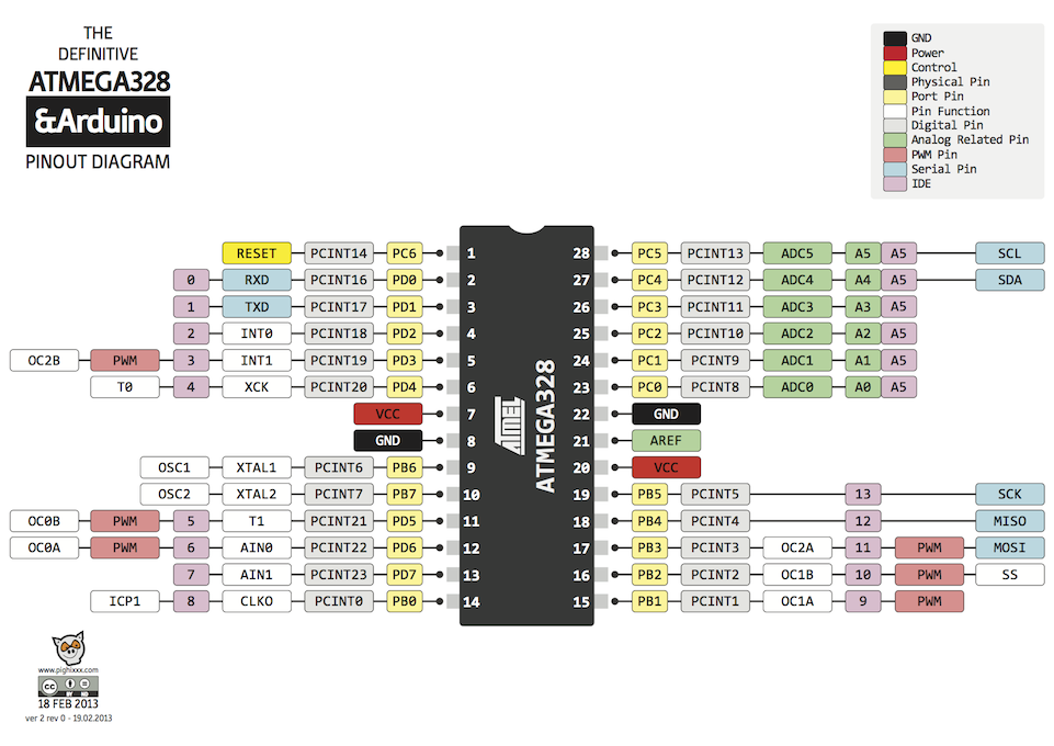
"B0" is the Port B - pin 0 as is the terminology in AVR compiler ("port pins"). It is the parameter I need to add to GCC compiler to be able to use that pin.In Arduino IDE terms this is digital arduino pin nr 8. On the DIL version of the chip it is physical pin nr 14. The Arduino IDE makes abstraction of the port pins, by designating numbers to the pins of various ports. The relation between the two can be found in the file "pins_arduino.h", which is stored in a subdirectory "variants". This allows the IDE to use the same number of "pin" for different versions of boards and processors.
In this file you will find (for the "standard" Arduino Uno the following comments:
// ATMEL ATMEGA8 & 168 / ARDUINO
//
//                  +-\/-+
//            PC6  1|    |28  PC5 (AI 5)
//      (D 0) PD0  2|    |27  PC4 (AI 4)
//      (D 1) PD1  3|    |26  PC3 (AI 3)
//      (D 2) PD2  4|    |25  PC2 (AI 2)
// PWM+ (D 3) PD3  5|    |24  PC1 (AI 1)
//      (D 4) PD4  6|    |23  PC0 (AI 0)
//            VCC  7|    |22  GND
//            GND  8|    |21  AREF
//            PB6  9|    |20  AVCC
//            PB7 10|    |19  PB5 (D 13)
// PWM+ (D 5) PD5 11|    |18  PB4 (D 12)
// PWM+ (D 6) PD6 12|    |17  PB3 (D 11) PWM
//      (D 7) PD7 13|    |16  PB2 (D 10) PWM
//      (D 8) PB0 14|    |15  PB1 (D 9) PWM
//                  +----+
//
// (PWM+ indicates the additional PWM pins on the ATmega168.)
In the diagram below you see the relation between IDE, physical and ATMEL definition of the pins for the DIL variant.
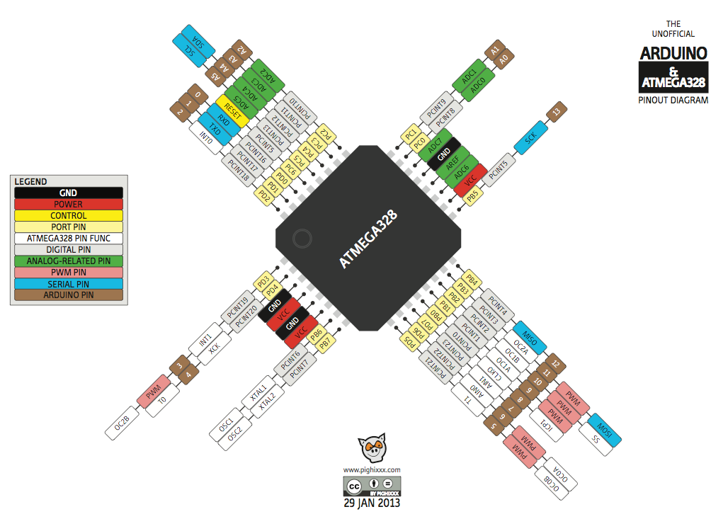
In this diagram below you see the CPU variant used on the Pro Mini. Port B, pin 0 is here physical pin 12, but for Arduino IDE this is still digital pin number 8:
-
will there be an "Arduino Pro Mini" (Using external 8MHz scaled to 1MHz="X8M1") with LED B5 blink -> optiboot_atmega328_X8M1_057600_B5.hex avialable? preferable with BOD=disabled or set to 1,8v
-
@GertSanders Perfect !!!
-
Try this one.
0_1457034725597_optiboot_atmega328_X8M1_057600_B5.hex
I doubt uploading will work since 57600baud for a 1MHz device will generate around 8% error, which is way above the 2% AVRDUDE tolerates (I think). For the error calculation see below (WormFood's...)
But test it. I may be wrong.
I will make a 4800 baud version if you want later.
The BOD setting is something independent of the boot loader, you choose this with the fuses.
This boot loader expects to run at 1MHz, so you can either choose the internal 8MHz oscillator or a crystal at 8Mhz and set the fuses for clock division by 8. The clockdivision is also decided via the fuses and independent of the boot loader itself.There are only a few things that are important to a boot loader as far as I know:
Frequency of the cpu needs to be known at compile time, so that functions like wait() and delay() have an exact time reference (meaning that wait(1000) take 1 second and not some other duration).
Speed of the expected uploads also needs to be known, so that it can match the speed used to upload sketches. Not all combinations of cpu frequency and upload speed are possible. Some combinations have too much error. Google the "WormFood's AVR Baud Rate Calculator" and you will find info on this.
In the boards.txt file of the Arduino IDE you need to match the cpu and upload frequency.The fact that a LED needs to flash also needs to be known when compiling the boot loader (it's a parameter
This is how I started the make tool for Optiboot compilation for your bootloader:
make atmega328 BAUD_RATE=57600 AVR_FREQ=1000000L LED_START_FLASHES=3 LED=B5
Fuse settings:
For Clock division by 8
Internal 8Mhz oscillator
BOD at 1.8V:
Low: 0x62
High: 0xDF
Extended: 0xFE (or 06 in the boards.txt)For Clock division by 8
External Full Swing 8Mhz crystal
BOD at 1.8V:
Low: 0x77
High: 0xDF
Extended: 0xFE (or 06 in the boards.txt)For No BOD at all, Low and High fuses stay the same, only the Extended fuse changes:
Extended: 0xFF (or 07 in the boards.txt)Let me know if you can get it to work.
-
I tried to compile as you write that my baudrate was unrealistic high. to get a 4800 baudrate hexfile
I downloaded from github optiboot, and tried your compile settings, but get an AVR_FREQ error. I can understand that the AVR_FREQ isn't correctly taken as input from the commandline ans used by the makefile
I'm on Ubuntu Linux/media/bjacobse/documents/Downloads/optiboot-master/optiboot/bootloaders/optiboot$ make atmega328 BAUD_RATE=4800 AVR_FREQ=1000000L LED_FLASHES=3 LED=B5
avr-gcc (GCC) 4.8.2
Copyright (C) 2013 Free Software Foundation, Inc.
This is free software; see the source for copying conditions. There is NO
warranty; not even for MERCHANTABILITY or FITNESS FOR A PARTICULAR PURPOSE.avr-gcc: error: 000L: No such file or directory
make: [baudcheck] Error 1 (ignored)
baudcheck.tmp.sh: line 17: ( (H�00 + 4800 * 4) / ((4800 * 8))) - 1 : syntax error: invalid arithmetic operator (error token is "�00 + 4800 * 4) / ((4800 * 8))) - 1 ")
baudcheck.tmp.sh: line 25: (H�00/(8 * (()+1))) : syntax error: invalid arithmetic operator (error token is "�00/(8 * (()+1))) ")
BAUD RATE CHECK: Desired: 4800, Real: , UBRRL = , Error=-100.0%
avr-gcc -g -Wall -Os -fno-split-wide-types -mrelax -mmcu=atmega328p -DF_CPU=HW� 000L -DBAUD_RATE=4800 -DLED_START_FLASHES=3 -DLED=B5 -c -o optiboot.o optiboot.c
avr-gcc: error: 000L: No such file or directory
make: *** [optiboot.o] Error 1
-
You can not just compile on linux. The make file needs to be adapted to your setup. I compile my bootloaders on a Mac within a virtual machine running WinAVR version 2010 (oktober).
Tomorrow I will make a 4800 baud version. The 9600 baud 1Mhz should work as well, but the errorrate for uploads will be higher. Seems acceptable on some peoples boards.
-
-
@GertSanders
Thank you for the file, however I have some troubles, I can flash via USBtiny but I am not able to upload sketch via Arduino IDE+ FTDI,
will you check my settings are correct?Here is my boards.txt file for the optiboot
##############################################################pro328opti.name=BJa BOD 1,8V Optiboot, Arduino Pro Mini (3.3V, 8 MHz) w/ ATmega328
pro328opti.upload.protocol=arduino
pro328opti.upload.maximum_size=30720
pro328opti.upload.speed=4800pro328opti.bootloader.low_fuses=0x77
pro328opti.bootloader.high_fuses=0xDF
pro328opti.bootloader.extended_fuses=0x06
pro328opti.bootloader.path=optiboot
pro328opti.bootloader.file=1457256062840-optiboot_atmega328_x8m1_004800_b5.hex
pro328opti.bootloader.unlock_bits=0x3F
pro328opti.bootloader.lock_bits=0x0F
pro328opti.build.mcu=atmega328p
pro328opti.build.f_cpu=8000000L
pro328opti.build.core=arduino
pro328opti.build.variant=standard
-
As you use the clock divider, you should inform the Arduino IDE that the processor is running slower.
So you need to set this:
pro328opti.build.f_cpu=1000000L
-
Sounds like good idea
") Thanks
Thanks
now the board.tx file is updated: pro328opti.build.f_cpu=1000000L
restart Arduino, but still get upload errors
Error messages:
Binary sketch size: 1,102 bytes (of a 30,720 byte maximum)
avrdude: stk500_recv(): programmer is not responding
avrdude: stk500_getsync() attempt 1 of 10: not in sync: resp=0x00
I feel it's an unlucky Sunday... Can you provide more ideas what I can do?
-
Not sure, but an out of sync message is usually because of a mismatch in speed between what the IDE en avrdude expect, and what the cpu does.
So I would check the fuses of the cpu to be sure. I will try this boot loader on one of my nodes to see if the boot loader itself is the problem.
-
@GertSanders I installed your compiled bootloaders - thanks for compiling them, but I cannot compile a Blink sketch using 1Mhz internal one
Board GertSanders:avr:atmega328pO5M16c doesn't define a 'build.board' preference. Auto-set to: AVR_ATMEGA328PO5M16C
Board GertSanders:avr:atmega328pO5M8c doesn't define a 'build.board' preference. Auto-set to: AVR_ATMEGA328PO5M8C
Board breadboard:avr:atmega328bb doesn't define a 'build.board' preference. Auto-set to: AVR_ATMEGA328BB
WARNING: Category '' in library UIPEthernet is not valid. Setting to 'Uncategorized'
Build options changed, rebuilding all
In file included from sketch\Blink.ino.cpp:1:0:

C:\Program Files (x86)\Arduino\hardware\arduino\avr\cores\arduino/Arduino.h:249:26: fatal error: pins_arduino.h: No such file or directory

#include "pins_arduino.h"

                         ^

compilation terminated.

exit status 1
Error compiling.```
-
My boards.txt file is pointing to a location you are not using.
You have your library in a different place then I.
You should make sure that the directory in which you put the variant matches with what you have. I can not know which directory you put the Arduino IDE, so matching this is an exercise for you
")
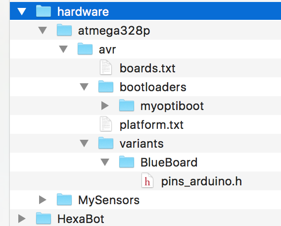
In my case, my variants boards is here:
\Dropbox\Arduino\hardware\atmega328p\avr\variants\BlueBoard\pins_arduino.h
This is matched with the fact that my boards file is here:
\Dropbox\Arduino\hardware\atmega328p\avr\boards.txt
Within the boards.txt file, I'm referring to the following variant: "BlueBoard". This is done here:
BlueBoard.build.core=arduino:arduino
BlueBoard.build.mcu=atmega328pBlueBoard.build.board=AVR_GERTSANDERSBLUEBOARD
BlueBoard.build.variant=BlueBoardYou seem to have a different path:
C:\Program Files (x86)\Arduino\hardware\arduino\avr\cores\arduino
I'm not sure where you added my files or boards.txt, but do not just copy it. You need to adapt your boards.txt file.
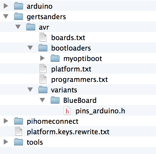
My "hardware" directory is within the Arduino sketch directory and contains this:
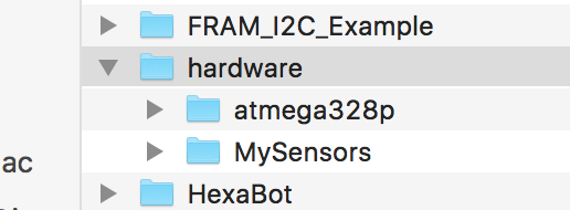
All my boot loaders are in directory "bootloaders\myoptiboot":
the file pins_arduino.h is a pins layout file for a standard atmega328p (copied from the "standard" variant directory.
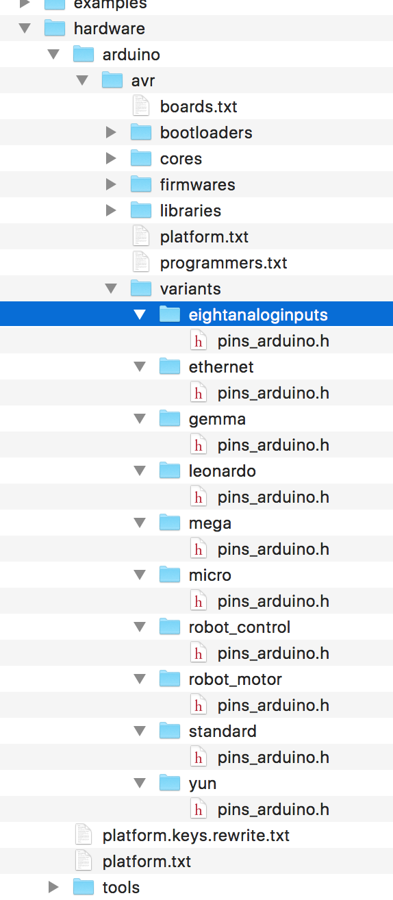
If you have a pro micro with the flat atmega328p, you need to use the "eightanaloginputs" variant.
This is what it looks like in my Arduino IDE installation directory:
-
@GertSanders said:
I'm not sure where you added my files or boards.txt, but do not just copy it. You need to adapt your boards.txt file.
That's what I did - I adopted your boards.txt
All my bootloaders are in the hardware directory (C:\Users\Alex\Documents\Arduino\hardware). The hardware directory is located together with all my sketches in the Arduino directory. Now, for whatever reason, the error is point out to the completely different location:C:\Program Files (x86)\Arduino\hardware\arduino\avr\cores\arduino
C:\Program Files (x86)\Arduino\hardware\arduino\avr\cores\arduino
-
@GertSanders OK, I sorted it out.
I had to create "BlueBoard" and "standard" under "variants" and copy two corresponding files pins_arduino.h
At least I can compile now.Will try to upload a sketch later on and see if it works.
-
@GertSanders Unfortunately, I was able to upload the bootloader, but was not able to upload any sketches on the breadboard:
avrdude: stk500_getsync() attempt 1 of 10: not in sync: resp=0x78
avrdude: stk500_getsync() attempt 2 of 10: not in sync: resp=0xc0
avrdude: stk500_getsync() attempt 3 of 10: not in sync: resp=0x78
Not sure why - I can upload a sketch via the programmer though. Will upload Nick Gammon sketch to test the bootloader.
UPDATE1: Nick Gammon's sketch cannot detect the bootloader (tried 1MHz internal). Once again, I uploaded the bootloader (1Mhz internal) and the sketch via the programmer and it works, but....the serial monitor works only on 74880, despite for "1Mhz internal" boards.txt clearly says "9600":
BlueBoard.menu.mhz.1Mi= 1Mhz - internal - 9K6 upload speed
BlueBoard.menu.mhz.1Mi.bootloader.low_fuses=0xE2
BlueBoard.menu.mhz.1Mi.bootloader.high_fuses=0xDE
BlueBoard.menu.mhz.1Mi.build.f_cpu=1000000L
BlueBoard.menu.mhz.1Mi.upload.speed=9600
BlueBoard.menu.mhz.1Mi.bootloader.file=myoptiboot/optiboot_atmega328_01M_009600_B0.hex
Additionally, I loaded the ASCIITable example sketch and it states " Serial.begin(9600);"
I do not understand why it works only on 74880...
-
I will do some testing tonight, I have not used the 1MHz bootloader yet.
The instruction Serial.begin(9600) is independant of the upload.speed mentioned in the boards file. But I would expect that at 1MHz the higher serial comms speeds also give errors.
A possible reason for the problem, is that the fuse E2 actually means that you run the processor at 8Mhz internally, but without any clock division, while the bootloader was compiled for 1MHz. Without clock division by 8 the processor actually runs at 8Mhz (the speed of the internal oscillator), while all timing code is set for a cpu working frequency of 1Mhz. This would also explain why you can communicate at 74880 (which is close to 76800, which in turn is 8 times 9600).
I think the fuse should be set to both internal 8MHz oscillator AND clock division by 8. I do not know that correct value by hart, need to check that with a fuse calculator.
UPDATE: I think the lower fuse should be set to 0x62 instead of 0xE2.
-
OK, I have come to the following fuse settings for 1Mhz internal:
BlueBoard.menu.mhz.1Mi.bootloader.low_fuses=0x62
BlueBoard.menu.mhz.1Mi.bootloader.high_fuses=0xDE
For Optiboot, the high fuse is always 0xDE.
Now, a standard example sketch runs at 9600 - I have not checked if atmega328p is running at 1Mhz.Still have a problem uploading a sketch on the breadboard via FTDI
-
I will do some tests later tonight.
-
I just loaded a blink sketch at 4800 baud using FTDI and that works with the following combination:
Boot loader:
0_1457554985438_optiboot_atmega328_08M1_004800_B0.hexFuses:
BlueBoard.menu.mhz.1Mi48= 1Mhz - internal 8MHz DIV 8 - 4K8 upload speed
BlueBoard.menu.mhz.1Mi48.bootloader.low_fuses=0x62
BlueBoard.menu.mhz.1Mi48.bootloader.high_fuses=0xDE
BlueBoard.menu.mhz.1Mi48.build.f_cpu=1000000L
BlueBoard.menu.mhz.1Mi48.upload.speed=4800
BlueBoard.menu.mhz.1Mi48.bootloader.file=myoptiboot/optiboot_atmega328_08M1_004800_B0.hexYou will have to strip the "0_1457554985438_" part from the uploaded filename.
Loading the sketch is VERY slow, but it works perfectly. The Blink sketch blinks the led at 500ms on and 500ms off, and that is checked on the breadboard.
Whether the processor actually runs at 1MHz I do not know for sure, since I have no frequency meter (still missing from my toolbox).
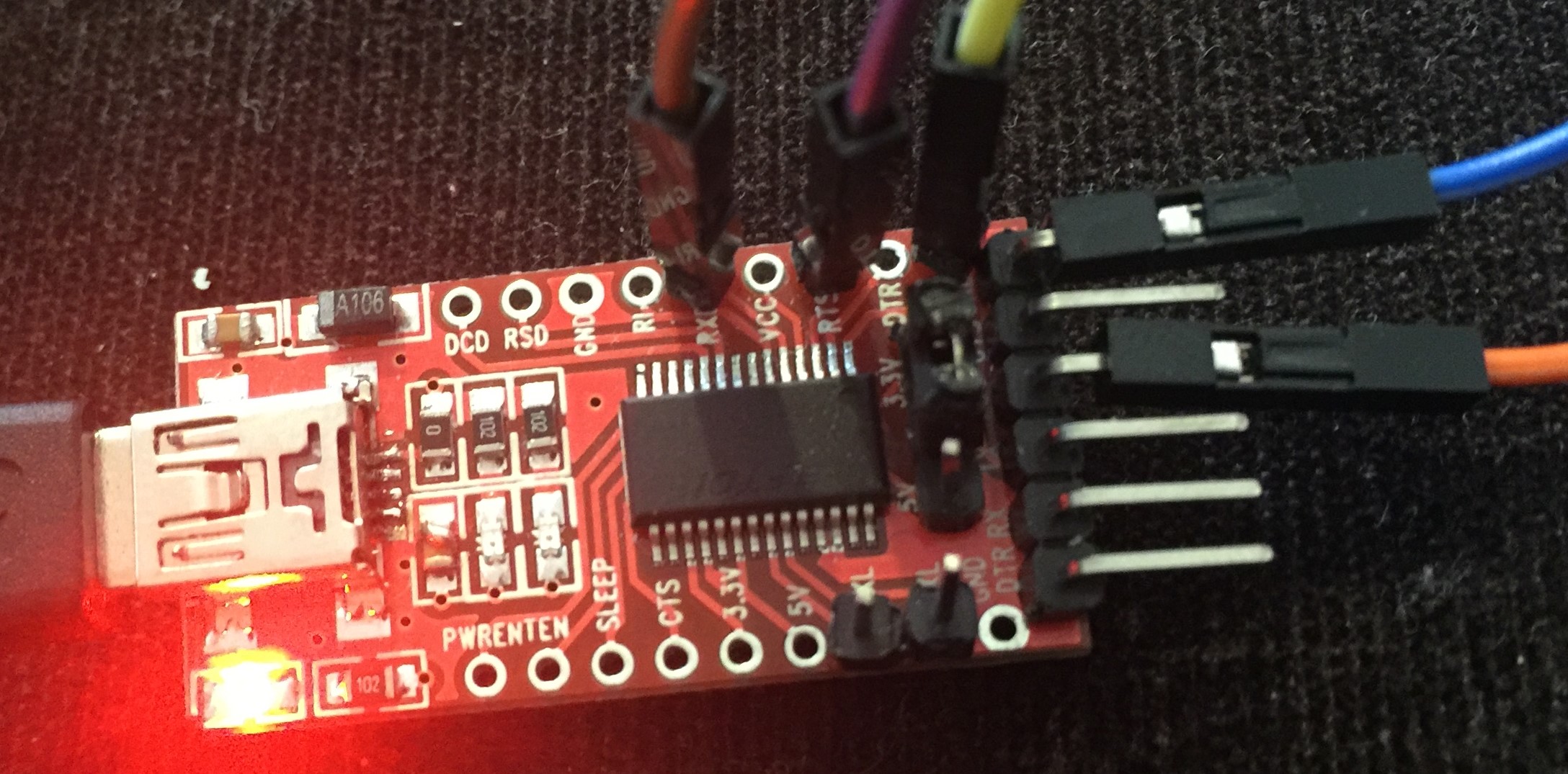
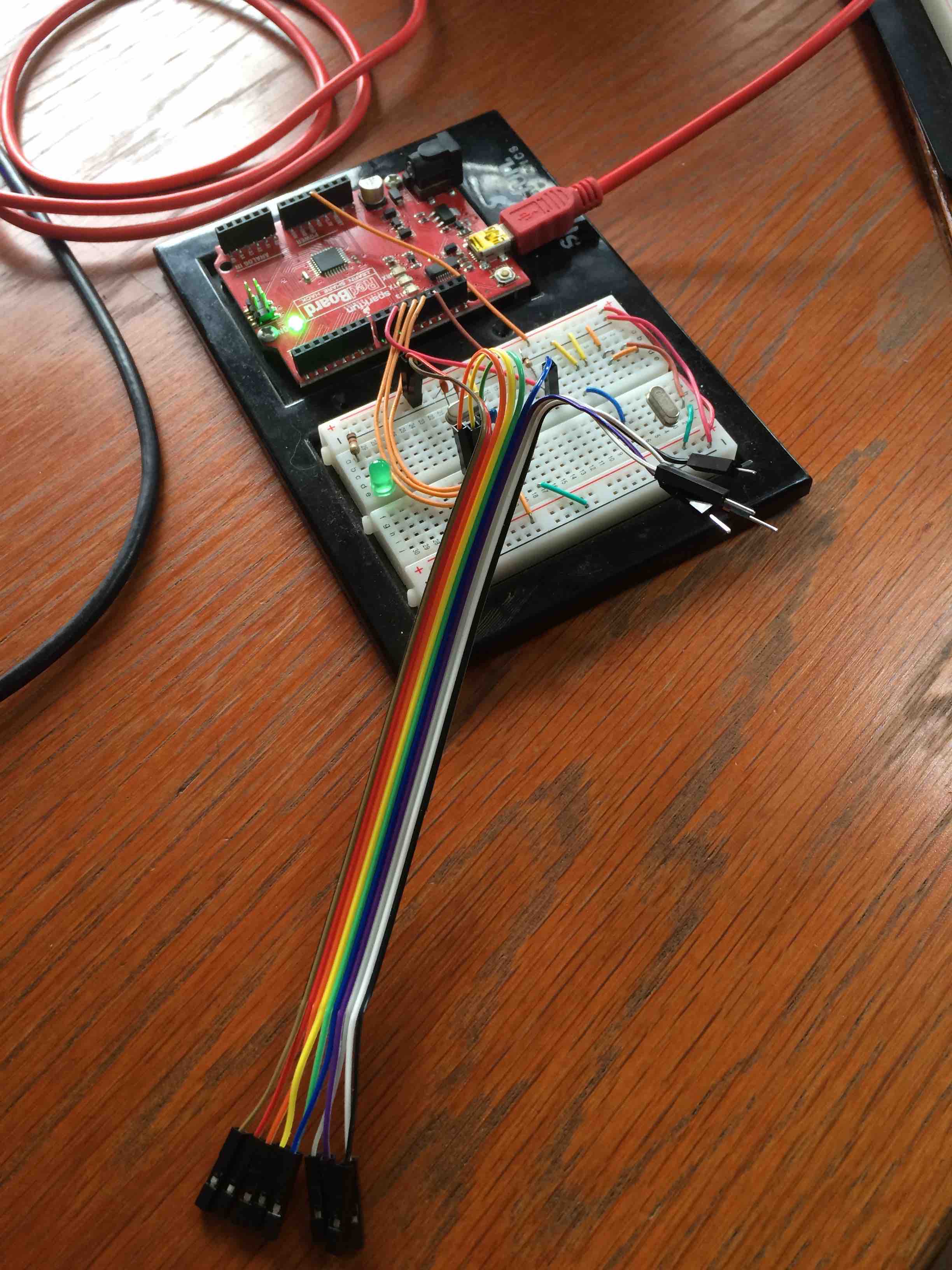
I used an arduino as ISP to load the boot loader, and then used an FTDI interface (from Adafruit) to load the sketch while the atmega328 was plugged in a breadboard (Gammon style).
Next I will try with the 9600 baud version at 1Mhz.
-
@GertSanders said:
Next I will try with the 9600 baud version at 1Mhz.
THanks
I'm looking forward to this - 4800 is way too slow.
I think the way to check the frequency is to time delay(1000); in the blink sketch...
-
I just tested with the 9600 baud version at 1MHz, and the blink sketch at 250ms, 500ms and 1000ms per on/off cycle. All rock solid and as expected.
Here is the setup I tested the transfer with FTDI:
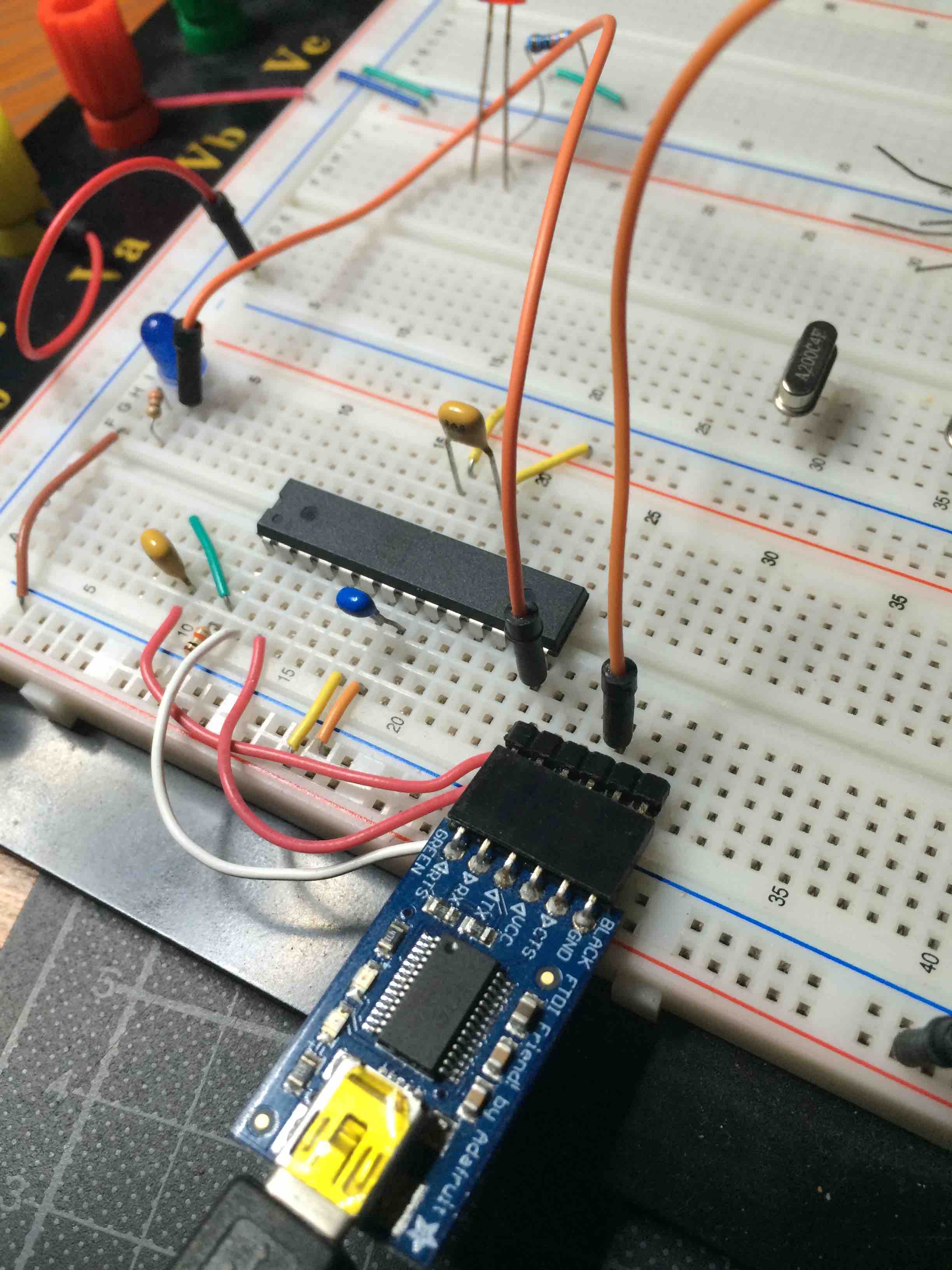
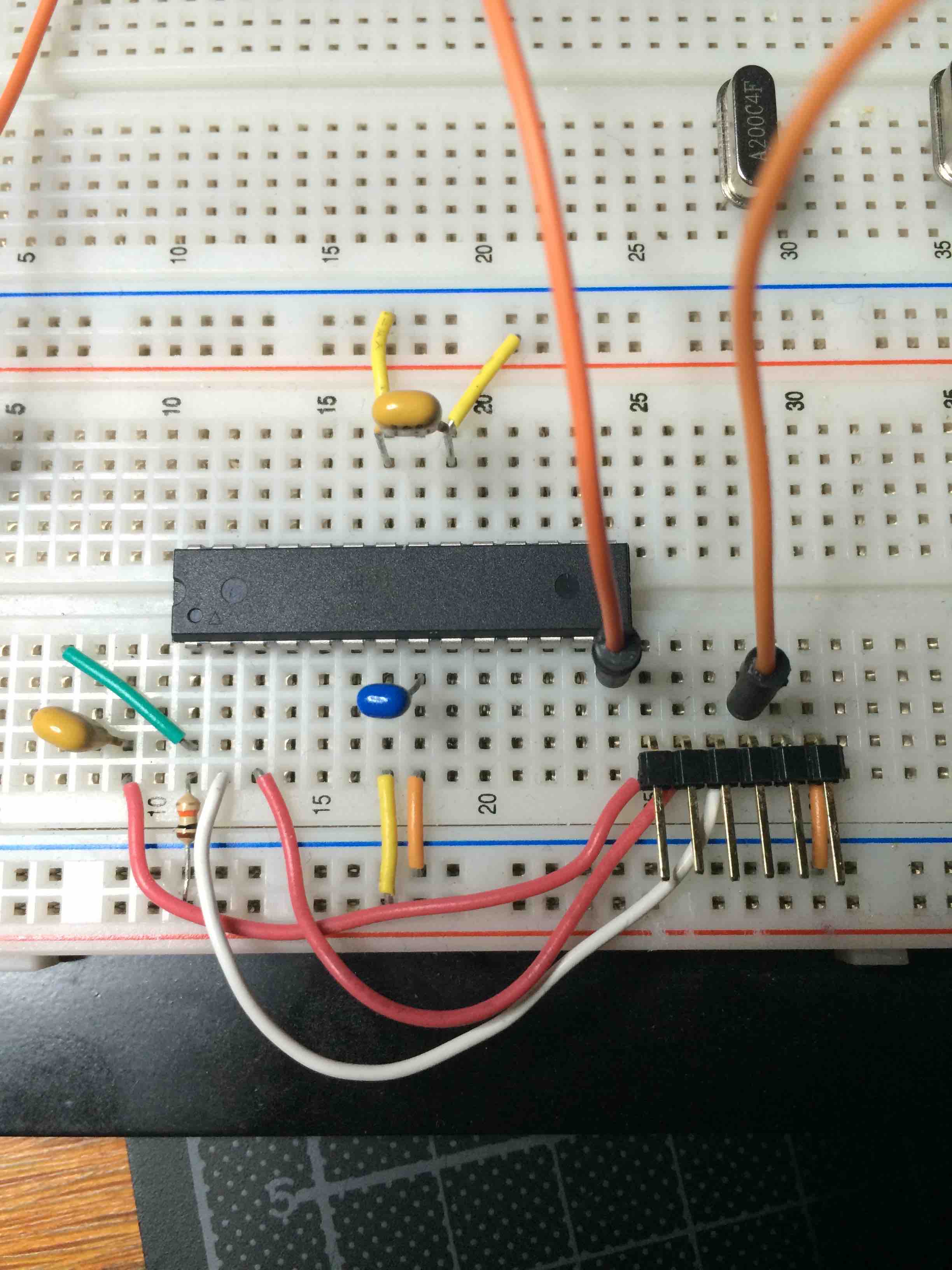
I used the following combination:
Boot loader:
0_1457556618255_optiboot_atmega328_01M_009600_B0.hex
Fuses:
BlueBoard.menu.mhz.1Mi= 1Mhz - internal 8MHz DIV 8 - 9K6 upload speed
BlueBoard.menu.mhz.1Mi.bootloader.low_fuses=0x62
BlueBoard.menu.mhz.1Mi.bootloader.high_fuses=0xDE
BlueBoard.menu.mhz.1Mi.build.f_cpu=1000000L
BlueBoard.menu.mhz.1Mi.upload.speed=9600
BlueBoard.menu.mhz.1Mi.bootloader.file=myoptiboot/optiboot_atmega328_01M_009600_B0.hexAlso here the "0_1457556618255_" is added by uploading on this forum, strip when downloaded.
Uploads were at twice the speed then before. Still slow, but acceptable.
-
@GertSanders I have the same breadboard setup, but can only read serial and cannot upload a sketch (out of sync). My settings are the same as yours as per my post earlier on today so I reckon it must be something wrong with the wiring on the breadboard since "Uploading using Programmer" works fine. Not sure what it is as I checked it a few times today.
-
@alexsh1
Maybe make a picture of your setup?
Upload using programmer means you use another Arduino to load the sketch on the atmega328, which at the same time deletes any bootloader.
I load bootloaders with an Arduino and the sketch ArduinoISP loaded on that one. Then I issue a "burn bootloader" command.
To load sketches I switch to my FTDI interface and upload sketches with the same processor setting. But as said with a different interface. And I do not use "upload using programmer", but the upload button next to the compile button.Maybe I should try to make a video like Mr Pete.
-
@GertSanders Yes, this is normally the way I do (burn bootloader and then upload a sketch via FTDI on the breadboard). Will post photos shortly.
Are you sure "Upload using programmer" deleting the bootloader?
-
Are you sure "Upload using programmer" deleting the bootloader?
Yes, looks like you are right - it kills the bootloader. So what's happening? I do not have any bootloader when I use this method to load up sketches?
-
If you load a sketch with "Upload using programmer" you replace anything in flash with the sketch. Just the sketch will run on the mcu.
In the very narrow node, there is no FTDI connector, so for those nodes it does not make sense to have a boot loader in flash (it does not hurt either). You couldvjust as well just load the sketch and skip the boot loader altogether.
If you need the extra 512 that optiboot occupies, then "Upload using programmer" allows you to recuperate that space.
So this shoudl explain why you can reed data from the Node via Serial (because the sketch is running and taking care of the serial connection), but why uploading a sketch fails, because for that you need a boot loader in flash.
-
I did a short video how I upload optiboot
Finally, success!
I think I had to reassemble the breadboard set-up three times before finally being able to upload the sketch. I think the problem was no connection at RTS, but I am not sure. I need to assemble a more permanent board to upload sketches via FTDI.
-
-
-
@GertSanders if I load a sketch via Upload using programmer - how do I control the frequency? (1Mhz or 8Mhz internal or external crystal)
-
@alexsh1 - You would do this by setting the correct fuses. Can you just confirm my information @GertSanders
I would also like to state that Atmel does not support or even recommend using FTDI with the internal crystal, my current board just will not upload via FTDI and no external crystal however yet a arduino pro mini does and that uses an external crystal with no other circuitry compared to my board apart from the physical reset switch.
-
@samuel235 said:
@alexsh1 - You would do this by setting the correct fuses. Can you just confirm my information @GertSanders
I think you have a point, but if I do not change anything, just use "Upload using programmer", what are the default frequency and fuses?
-
@alexsh1 If you haven't touched the ATmega328p then it should be sitting with fuses of; L:0x62 H:0xD9 E:0xFF, which would run the uC at 1MHz
-
@*alexsh1
*
Which fuses are set when loading a boot loader is defined by wich menu element in tools you have selected. Every processor or board you choose will correspond with values in a board.txt file.You can have several board.txt files: 1 file per "family" of boards.
When uploading sketches, the fusesettings are ignored, only the uploadspeed counts then. Both when uploading with Arduino as ISP as with FTDI interface.
The internal oscillator of 8 Mhz is not as accurate as a crystal, so at higher uploadspeeds the errorrate can increase or decrease depending on the mcu temperature.
Some uploadspeeds are closer to optimal then others in relation to the frequency at which the mcu works. The baudcalculator shows the errorrates. Most are non optimal. avrdude can handle an errorrate of 2% or less. So using a specific baudrate in combination with the internal 8Mhz oscillator depends on the worst case combination of transmission errorrate plus clock deviation error.
For most mcu's the rate of 9600 baud will be acceptable because at that slow rate a clockerror will be relative small. At higher speeds the small clockerror becomes more important. Then it is best to choose an upload speed close to the optimum.
The fusesettings are only burnt when loading a boot loader (within the Arduino IDE, in AVRStudio you can set fuses seperatly from loading anything).
The frequency of 8 Mhz can be obtained via a 8mhz crystal or the internal 8mhz oscillator. The low fuse value 0xE2 sets this internal oscillator. By using value 0x62 you also set the clock division bit in combination with the 8mhz internal oscillator, so your mcu will run at 8mhz / 8 = 1mhz
There are other division values possible. Calculate the low byte value using an avr fuse calculator.
You can also use an external 8 mhz crystal, and combine this with clock division by 8 to get 1mhz operation.
And you can choose an external 1mhz crystal.
All this from choose the right fuse bits.
Same for Brown out Detection which is set via the three least significant bits of the extended fuse.
-
@samuel235 This is strange. The serial monitor was working only on 74880 - I do not think the AVR was running @ 1Mhz
-
@GertSanders Thanks for a detailed write-up!
@GertSanders said:
You can also use an external 8 mhz crystal, and combine this with clock division by 8 to get 1mhz operation.
And you can choose an external 1mhz crystal.
How is this influencing low power though? My understanding is that such setup (external crystal) takes more power.
-
Using a 1mhz crystal would not be the best thing for low power use, you are correct there.
But it gives a more accurate clock base for the timing functions.
-
Not sure what happened, but the following error returned:
Board atmega328p:avr:atmega328pO5M8c doesn't define a 'build.board' preference. Auto-set to: AVR_ATMEGA328PO5M8C
Board atmega328p:avr:atmega328pO5M16c doesn't define a 'build.board' preference. Auto-set to: AVR_ATMEGA328PO5M16C
I did not change anything so very strange why it comes up.
-
Actually, i have no proof but i've been informed from the arduino standalone microcontroller forums, that using a external 8mhz crystal is good for power consumption. ONLY if its a sleeping module though, it enables it to perform its tasks quicker and then sleep quicker, resulting in more time sleeping.
That error code is something i ran into, i'm guessing you're working inside of arduino IDE, if so its to do with your boards.txt entry. Its missing that entry that it speak about. Check that its there, if not enter it in manually.
-
Thanks - yes you are right it is about boards.txt.
However, the problem is that I did not change anything. Two days ago I uploaded severa sketches and no errors were coming up and now two different boards are showing the same error. This is just odd...
-
@alexsh1, have you performed an Arduino IDE update? I had this exact issue simply because I updated my IDE.
-
This message pops up since IDE 1.6.7
The new IDE expects this entry for all boards, just add it or ignore (it's more a warning then an error).
-
And there you go, the forever informative @GertSanders has andwered your questioning
-
@samuel235 Looks like you are right - without realising I did press update button thinking about a sketch rather than about the update

Corrected this issue aleady in the boards.txt
-
@GertSanders Hello ! I am trying to upload a sketch without success for the moment.
Burning of the bootloader was done correctly (led on pin 8 lit three times) but impossible to load a sketch.
For easy deployment I choose to create a new folder to include your bootloaders:
But it seems that something is missing as upload is not possible:
Le croquis utilise 1 030 octets (3%) de l'espace de stockage de programmes. Le maximum est de 32 256 octets.
Les variables globales utilisent 9 octets (0%) de mémoire dynamique, ce qui laisse 2 039 octets pour les variables locales. Le maximum est de 2 048 octets.
/Applications/Arduino.app/Contents/Java/hardware/tools/avr/bin/avrdude -C/Applications/Arduino.app/Contents/Java/hardware/tools/avr/etc/avrdude.conf -v -patmega328p -carduino -P/dev/cu.usbmodem1411 -b38400 -D -Uflash:w:/var/folders/2y/_n7gfzjx5_sgmtyh9t_lp0wc0000gn/T/build8919458311701309495.tmp/Blink.cpp.hex:i

avrdude: Version 6.0.1, compiled on Apr 14 2015 at 16:30:25
         Copyright (c) 2000-2005 Brian Dean, http://www.bdmicro.com/
         Copyright (c) 2007-2009 Joerg Wunsch

         System wide configuration file is "/Applications/Arduino.app/Contents/Java/hardware/tools/avr/etc/avrdude.conf"
         User configuration file is "/Users/carlierd/.avrduderc"
         User configuration file does not exist or is not a regular file, skipping

         Using Port                    : /dev/cu.usbmodem1411
         Using Programmer              : arduino
         Overriding Baud Rate          : 38400
avrdude: ser_open(): can't open device "/dev/cu.usbmodem1411": No such file or directory
ioctl("TIOCMGET"): Inappropriate ioctl for device

avrdude done.  Thank you.

Problème de téléversement vers la carte. Voir http://www.arduino.cc/en/Guide/Troubleshooting#upload pour suggestions.
Any suggestion ?
David.
-
@carlierd
I am almost certain that you are NOT using my boards.txt because you put the bootloaders outside the reach of the IDE (must be in the sketchfolder and within the hardware subfolder of the sketches folder).
-
@GertSanders
No doubt that I using your file as I got the same problem as @alexsh1 with the arduino pin file.Look at my board choice:
I find this method very good for deployment but only when it's working
I check the bootloader with Nick Gammon sketch and it seems good.
David.
-
I burn the bootloader one more time and now I can upload without any change on configuration.
Perhaps I made a mistake the first time
I will continue my test.
David.
-
@GertSanders One more question on the LED connected on B0.
When you wrote that the LED lit on arduino reset, it's when the reset button is pushed ? when the arduino start ? or both ?
David.
-
When the atmega328 is reset, the LED will flash three times if the boot loader is in memory. This also happens when you send a new sketch via the Arduino IDE to the atmega328.
So if you connect pin 1 shortly to GND, the led should flash.
The first time you load a boot loader, the atmega328 will "loop" between the startup procedure of the boot loader (and will flash the led), and then try to load the sketch. If there never is a sketch, it will start the boot loader again and again ...
-
So it confirms that your bootloader was correctly burnt in the atmega as the first time I failed to upload a sketch the LED flash three time again and again !
Thanks !David.
-
Hello,
I tested two bootloaders today:
- optiboot_atmega328_08M_038400_B0.hex
- optiboot_atmega328_01M_009600_B0.hex
But I am pretty sure you already tested them.
I got some issue with 1MHz bootloader but probably because I am using signing feature.
I will check the forum to be sure.David.
-
@carlierd
Indeed I am using these two boot loaders already. The 1Mhz in my very slim nodes and the 8Mhz in the red board battery based nodes.
I also use the 16Mhz in my AC based board (as a repeater or as SMS gateway).
I will make an AC board with a 20Mhz crystal just to test the faster versions of the bootloader.
-
Hello, as I got some issue with the 1MHz bootloader, I tried without the signing feature and I still got st=fail.
One question for you, perhaps stupid but I need to be sure
Do you need to set the same serial speed on both node and gateway ?David.
-
@carlierd
No, the serial speed is not something relevant for the radio communication.
When I compile the boot loader, I just need to choose the CPU frequency and make sure I also choose an upload speed which is compatible with that CPU frequency. Some combinations of CPU frequency and upload speed give errors and the error rate of the serial upload communication can not be above 2% or AVRDUDE will fail.
For node to gateway communication (and your ST=FAIL errors) this is not relevant.
ST=FAIL errors can (in my case) be reduced by lowering the power output of the radio on the node (is default set to MAX, I put it mostly to HIGH).
st=fail errors can also be the result of poor power to the radio.
-
@GertSanders said:
ST=FAIL errors can (in my case) be reduced by lowering the power output of the radio on the node (is default set to MAX, I put it mostly to HIGH).
st=fail errors can also be the result of poor power to the radio.Or just a bad radio. There is a huge thread on the forum about fake radio modules.
I have gone through quite a few - what a waste of time....
-
I am using RFM69. No fake as it's working perfectly at other frequency.
@GertSanders
I tried three different configurations:- 16 MHz with crystal
- 8 MHz internal
- 1 MHz internal (with some st=fail)
I measured power consumption in sleep mode and found that it's very close to 4uA with all configurations. So why using the 1 MHz ? Do you have better consumption when using 1 MHz ?
The best configuration for me will be the 8 MHz internal as it avoid to used the crystal.
David.
-
@carlierd
In sleep mode it does not matter which frequency is used. The watchdog timer runs off its own clock and that is the same for all three cases. The fact that you get around 4 uA is just because you still have a watchdogtimer running. With full deep sleep and complete shutdown of the radio we should see 1-2 uA if external pullup of more then 2MOhm is used.
The mcu frequency is important for the active time. Higher frequency means faster startup and faster completion of tasks.
8Mhz is a good compromise as the internal oscillator is less powerhungry then fullswing crystal.
And you need less parts.
-
@carlierd, all that i can say is; do not rely on serial communication working. I'm running my custom made node on 8MHz internal, can use the serial monitor but i can not upload via serial. Only ISP uploads using programmer.
-
@Samuel235
I have no issues with ftdi uploads at 8Mhz internal and 38k upload speed on my nodes. Even for 25k byte sketches.
-
@GertSanders said:
@Samuel235
I have no issues with ftdi uploads at 8Mhz internal and 38k upload speed on my nodes. Even for 25k byte sketches.I've been told that it should work but atmel do not advise it or support it apparently. There are chances that it wont work and mine doesn't. I had the discussion regarding it in my nodes topic but the conversation just dropped off and went stale.
-
@Samuel235
That depends on the upload speed. At higher speeds the error on the frequency of the internal oscillator gets more important. It can be off by several percent (from 8mhz) and then avrdude can fail. I have experimented with 9600 baud and there the deviation of the internal 8mhz has to be severe before the serial uploads starts to feel the effect.
So try using a 8Mhz boot loader prepared for an 9600 baud upload.
-
@GertSanders, i did do, that's the latest solution i tried. No joy.
-
@GertSanders Thanks for explanation. It confirms what I imagine !
I am using a 10MOhm resistor but not the full deep sleep as I want to periodically send the battery.
I will try it because 1-2 uA is very low
-
@Samuel235 No issue to with the FTDI.
I just found a small problem due to the Arduino IDE. As I often change board (from UNO to different bootloader) I discover that the menu is sometime not coherent with the real setting. So I found that selecting two or three times board parameters (including port) is the solution to avoid communication issue.
-
@Samuel235
Would you want to try a bootloader with an upload speed of 4800 ? I can make that for 8Mhz if you want (just to test)?
-
@GertSanders, that would be fantastic if you wouldn't mind. Its for my in wall light switch custom made node that you're following. Thanks you, much appreciated.
-
here is the boot loader in 2 versions: one will flash port PB0 and the other does not.
You need to use the following fuse settings in the board file:
bootloader.low_fuses=0xE2
bootloader.high_fuses=0xDE
bootloader.extended_fuses=0x061_1458903521561_optiboot_atmega328_08M_004800_NOLED.hex
0_1458903521561_optiboot_atmega328_08M_004800_B0.hex
I saw that you use high fuse 0xDA
I'm assuming you use a boot loader larger then 512 bytes. Optiboot fits inside 512 bytes, so we need to define a space of 256 words (1 word = 2 bytes in AVR 8bit).
-
For my boot loaders based on Optiboot 6.2, I normally use high fuse set to 0xDE
Extract from my boards.txt file:
menu.mhz=CPU Speed
menu.bod=Brown Out Detection28PinBoard.name=atmega328p based - 28 pin DIL
28PinBoard.upload.tool=arduino:avrdude
28PinBoard.upload.protocol=arduino
28PinBoard.upload.maximum_size=32256
28PinBoard.upload.maximum_data_size=204828PinBoard.bootloader.tool=arduino:avrdude
28PinBoard.bootloader.unlock_bits=0x3F
28PinBoard.bootloader.lock_bits=0x0F28PinBoard.build.core=arduino:arduino
28PinBoard.build.mcu=atmega328p28PinBoard.build.board=AVR_GERTSANDERS28PinBoard
28PinBoard.build.variant=28PinBoard28PinBoard.menu.bod.4v3=4V3
28PinBoard.menu.bod.4v3.bootloader.extended_fuses=0x04
28PinBoard.menu.bod.2v7=2V7
28PinBoard.menu.bod.2v7.bootloader.extended_fuses=0x05
28PinBoard.menu.bod.1v8=1V8
28PinBoard.menu.bod.1v8.bootloader.extended_fuses=0x06
28PinBoard.menu.bod.off=Disabled
28PinBoard.menu.bod.off.bootloader.extended_fuses=0x0728PinBoard.menu.mhz.8Mi-38K4-D8= 8Mhz - internal - 38K4 - D8
28PinBoard.menu.mhz.8Mi-38K4-D8.bootloader.low_fuses=0xE2
28PinBoard.menu.mhz.8Mi-38K4-D8.bootloader.high_fuses=0xDE
28PinBoard.menu.mhz.8Mi-38K4-D8.build.f_cpu=8000000L
28PinBoard.menu.mhz.8Mi-38K4-D8.upload.speed=38400
28PinBoard.menu.mhz.8Mi-38K4-D8.bootloader.file=myoptiboot/optiboot_atmega328_08M_038400_B0.hex
-
@GertSanders I used that DA high fuse simply to make sure the default bootloader fitted, however if its too big will it cause issues on serial ipload even if its a very small upload? Could that be the reason?
I will try your bootloader without the LED as my module doesn't contain the LED. This is very hard to read from a mobile device so i will attempt this when i get home tonight. Thank you once again for your files and time.
-
@GertSanders Hello. I tried the full deep sleep and it's really amazing !
I used your 8MHz with internal crystal and B0 led, BOD disabled. RFM69 for radio and just a switch via a 10MOhm resistor.
With the switch open: 280nA
With the switch close: 580nAMeasures done with a uCurrent Gold.
So I am sure now that I found the good bootloader for my application. It's simple to install and I can change easily the BOD !
Thanks !
-
@carlierd
Great to hear those low consumption numbers.
-
@GertSanders
Yes, very impressive ! But finally not a lot of difference with the same node using interruption and sleep.
The auto-discharge of AA batteries is really important compare to node consumption.David.
-
@GertSanders, I have just managed to make time to remake a node and troubleshoot its upload issues with your suggested solution. So i went a head, got everything made up the minimal version, MCU, caps, and programming headers. I made sure all connections were working fine, they were. I then read the fuses, all fine and dandy. I then burnt your suggested fuses of;
bootloader.low_fuses=0xE2 bootloader.high_fuses=0xDE bootloader.extended_fuses=0x06Then the problem came. I lost all contact to the node, tried slowing the clock rate down on AVRDUDE to read it, nothing. I've hooked up my crystal just in case it burnt it incorrectly and thought it had an external crystal, nothing there either.
I'll be honest, i'm a little confused.
-
@Samuel235
I'm out of ideas myself. I have been using several boot loader versions with the LED on different pins and different upload speeds or clockspeeds, and so far all my boot loaders work on my nodes.
Maybe you should write down step by step what you do, without assuming we know which steps you take, so we can see if the procedure is correct. Other then that it could be a board issue, but then if you already have a working board which allows uploading ???
-
Here is the process i have gone through so far:
- Soldered the MCU in place.
- Soldered the ISP and FTDI header in place.
- Soldered the Capacitors and resistor in place.
- Connected the board to PC through ISP.
- Checked for continuity through-out the board on all ISP header Pins and corresponding MCU pins.
- Check for correct voltage on all of the VCC and GND points.
- Ran a fuse check on AVRDUDE and got back all the default fuses.
- Checked that your fuses were going to be okay with my board using the fuse calculator.
- Entered your suggested fuse settings into AVRDUDE and burned.
- Went to read the fuses (like i always do after burning them to double check they have been applied). Got no answer for the device.
- Disconnected and connected the board back and read fuses over and over again with no hope with all of the speed options available within AVRDUDESS.
- Connected a 8MHz external crystal and checked for fuse readings yet again, nothing.
- Came here to see if you have any idea what has happened.
I didn't even get to the point of choosing one of your bootloaders that you gave me to try, so i'm more than sure it is either a fuse problem or a board problem (which i'm doubtful of since it was working before i burned the new fuse settings).
I haven't soldered the Radio, the radio's capacitor, battery holder, or the screw terminal block. Other than that, everything else has been assembled. The only other hardware thing that it could be, but not sure why it would work until i burnt the fuse settings, is there may be a 4.7uF as one of the capacitors where it should be a 0.1uF. I have replaced the one on the reset line so i can guarantee it is not that one. The only other caps on the board are decoupling/filtering caps.
I do already have one board with the fuses that you saw me use before (which you questioned why i used the size of the boot sector that i did) and that is working perfectly fine. But as you know that is just running a sketch that was uploaded through "Upload using programmer".
-
@Samuel235
One possible reason: the BOD setting is now 0x06, which is the value if you use the Arduino IDE to burn the bootloader and set the fuses.
Since you use AVRDUDE ditectly, the extended fuse needs a different value (the one you get from the AVR fuse calculator at ATMEL).
I'm using my phone for this reply, so can not check the actual site right now
-
@GertSanders, you're correct in that. I encountered this issue with my first board but the avrdude still contacted the board unlike this one. To test this out would you suggest me trying to burn the bootloader with the Arduino IDE?
I will attempt this tomorrow if so.
-
@Samuel235
I just checked the avr calculator.
The extended fuse is FE for a BOD at 1.8V
Low E2 means internal oscillator. So that should be OK.I always use an arduino as ISP programmer when loading a bootloader onto a blank atmega328.
Tomorrow I will also test a new board with the AU variant (smd) of the mcu. Should be similar to your setup.
-
Just to keep you updated on the situation @GertSanders;
I have now double checked it hasn't burnt a external 8MHz crystal fuse setting, which it hasn't. I can't check for 16MHz setting as i do not have a 16MHz crystal or a board with one on. I will be making a new board later with a fresh MCU to see if it happens all over again. I need to stock up on 0.1uF caps to make any more boards after this one today so this is my only option for the moment.
Keep me posted on your AU style board that you're assembling today
EDIT/UPDATE
After remaking another board, the only thing i can think i did incorrectly was burn a high fuse of 0xEE. This would disable all SPI downloads and turn on watch dog timer. Do you think this may be whats happened here?
The new board is working perfectly fine. I've burnt the correct fuses and can read the fuses back.
I have downloaded your bootloader you included above (optiboot_atmega328_08m_004800_noled.hex). I made a new directory in 'C:\Program Files (x86)\Arduino\hardware\arduino\avr\bootloaders' called gertsoptiboot and saved the .hex file inside of there. So the overall directory of the bootloader is: 'C:\Program Files (x86)\Arduino\hardware\arduino\avr\bootloaders\gertsoptiboot\optiboot_atmega328_08m_004800_noled.hex'.
The board.txt file i have added your included text in there but i assumed that i need to change the bootloader file path and name, so my boards.txt entry for you looks like this;
##############################################################
##                        GERTSANDERS                       ##
##############################################################

menu.mhz=CPU Speed
menu.bod=Brown Out Detection

28PinBoard.name=atmega328p based - 28 pin DIL

28PinBoard.upload.tool=arduino:avrdude
28PinBoard.upload.protocol=arduino
28PinBoard.upload.maximum_size=32256
28PinBoard.upload.maximum_data_size=2048

28PinBoard.bootloader.tool=arduino:avrdude

28PinBoard.bootloader.unlock_bits=0x3F
28PinBoard.bootloader.lock_bits=0x0F

28PinBoard.build.core=arduino:arduino
28PinBoard.build.mcu=atmega328p

28PinBoard.build.board=AVR_GERTSANDERS28PinBoard
28PinBoard.build.variant=28PinBoard

28PinBoard.menu.bod.4v3=4V3
28PinBoard.menu.bod.4v3.bootloader.extended_fuses=0x04
28PinBoard.menu.bod.2v7=2V7
28PinBoard.menu.bod.2v7.bootloader.extended_fuses=0x05
28PinBoard.menu.bod.1v8=1V8
28PinBoard.menu.bod.1v8.bootloader.extended_fuses=0x06
28PinBoard.menu.bod.off=Disabled
28PinBoard.menu.bod.off.bootloader.extended_fuses=0x07

28PinBoard.menu.mhz.8Mi-38K4-D8= 8Mhz - internal - 38K4 - D8
28PinBoard.menu.mhz.8Mi-38K4-D8.bootloader.low_fuses=0xE2
28PinBoard.menu.mhz.8Mi-38K4-D8.bootloader.high_fuses=0xDE
28PinBoard.menu.mhz.8Mi-38K4-D8.build.f_cpu=8000000L
28PinBoard.menu.mhz.8Mi-38K4-D8.upload.speed=4800
28PinBoard.menu.mhz.8Mi-38K4-D8.bootloader.file=gertsoptiboot/optiboot_atmega328_08m_004800_noled.hex
I have changed the bottom two lines and will change the arduino menu name when its working. While this all like fine to me (obviously point out any errors for me here if i have done any) I'm getting a little error of "pins_arduino.h: No such file or directory". I have done a little searching around and basically i think its because i do not have a variant folder for this board/entry. I'm assuming that you have a subfolder inside of 'C:\Program Files (x86)\Arduino\hardware\arduino\avr\variants' titled something like "28PinBoard"?
To fix my issue i think i either need a copy of your variant folder OR to change the variant inside of boards.txt to that of something like 28PinBoard.build.variant=arduino:standard. Would this work considering there is nothing different on my MCU to that of a arduino board?
-
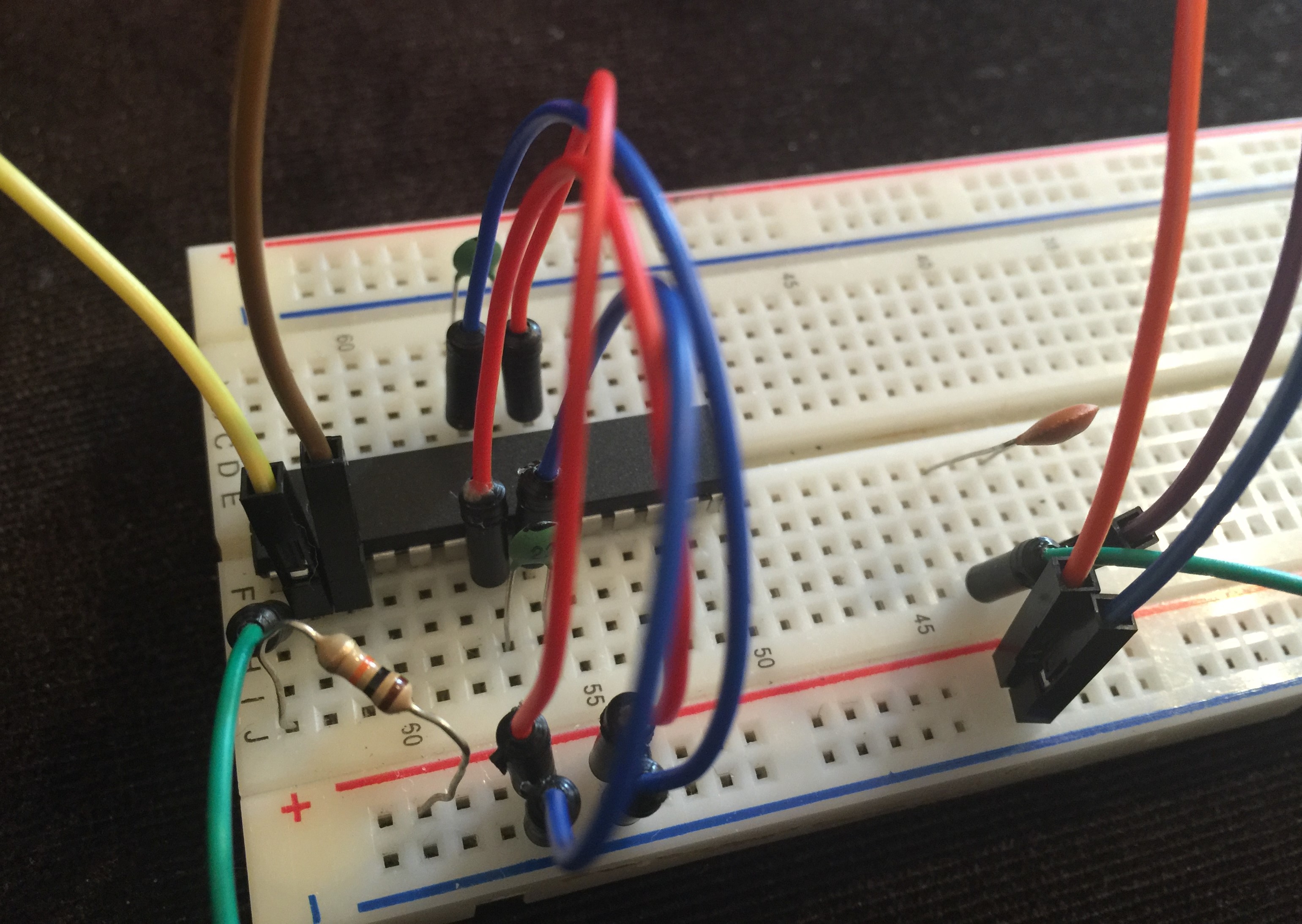
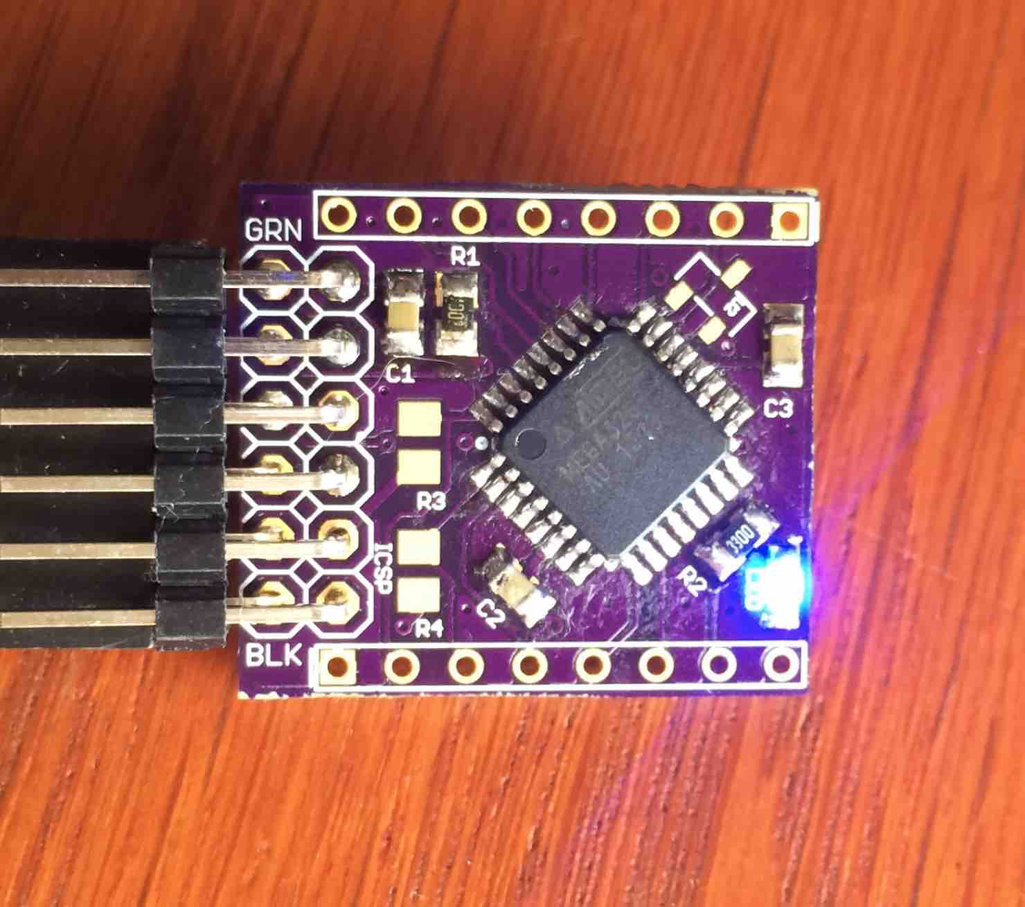
So here is my update: on my board I was able to upload my boot loader for 8MHz internal oscillator, with 34K8 upload speed and a led on pin D8. Here is the board running the "blink" sketch:
To make life easier I have zipped my complete folder, which I keep under the "hardware" folder in the sketches folder:
0_1460809951141_atmega328p.zip
I started with loading the ISP sketch on my Uno compatible board (it is set up for loading boot loaders on DIL type of atmega328):
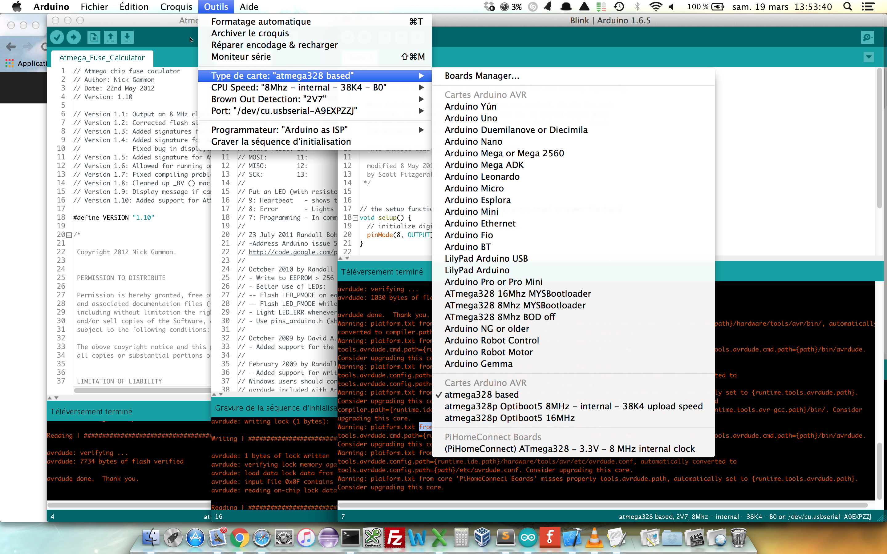
Then I choose the following settings in the Arduino IDE:
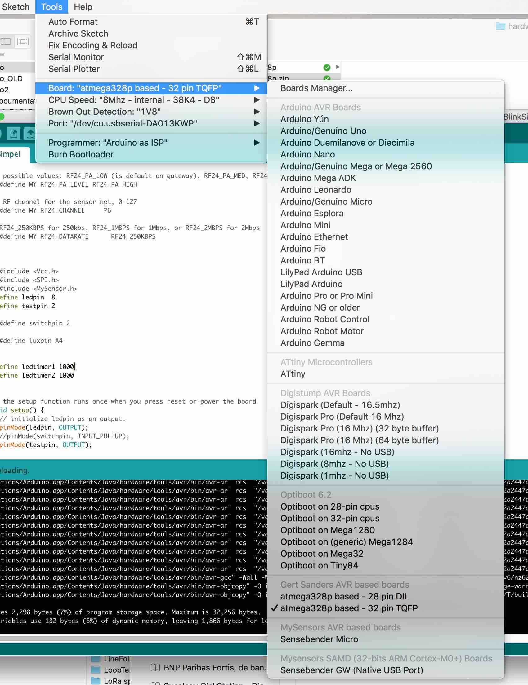
After choosing these settings I selected "Burn Bootloader", which resulted in a good loading. Since there is no sketch yet, my board cycles through a reset fase (and thus the LED blinks three times every few seconds).
After that I selected my FTDI interface and uploaded the BLINK sketch with the same settings, and bingo: blinky lights.
My next step will now be to add the radio and do a LED dimming test, to be continued ...
-
@GertSanders I will test this as we speak! May I ask if there is a difference between your DIL and TQFP entries in your boards.txt?
-
In the boards.txt you will see additional entries for the 32 pin version. These are basically a repeat of all the inputs for the 28 pin version.
So yes, there is a difference in the boards.txt file, but the boot loaders remain the same.
-
@GertSanders I'm sorry, I didn't look inside of the folder your provided before i asked that question.
-
Last update on this topic to save bogging it down now, just to assist anyone else looking to use your bootloaders. I have managed to upload sketches to my MCU. I'm running the 'optiboot_atmega328_08m_004800_noled.hex' bootloader with the following boards.txt entry:
##############################################################
##                        GERTSANDERS                       ##
##############################################################

menu.mhz=CPU Speed
menu.bod=Brown Out Detection

28PinBoard.name=atmega328p based - 28 pin DIL

28PinBoard.upload.tool=arduino:avrdude
28PinBoard.upload.protocol=arduino
28PinBoard.upload.maximum_size=32256
28PinBoard.upload.maximum_data_size=2048

28PinBoard.bootloader.tool=arduino:avrdude

28PinBoard.bootloader.unlock_bits=0x3F
28PinBoard.bootloader.lock_bits=0x0F

28PinBoard.build.core=arduino:arduino
28PinBoard.build.mcu=atmega328p

28PinBoard.build.board=AVR_GERTSANDERS28PinBoard
28PinBoard.build.variant=28PinBoard

28PinBoard.menu.bod.4v3=4V3
28PinBoard.menu.bod.4v3.bootloader.extended_fuses=0x04
28PinBoard.menu.bod.2v7=2V7
28PinBoard.menu.bod.2v7.bootloader.extended_fuses=0x05
28PinBoard.menu.bod.1v8=1V8
28PinBoard.menu.bod.1v8.bootloader.extended_fuses=0x06
28PinBoard.menu.bod.off=Disabled
28PinBoard.menu.bod.off.bootloader.extended_fuses=0x07

28PinBoard.menu.mhz.8Mi-38K4-D8= 8Mhz - internal - 4K8 - D8
28PinBoard.menu.mhz.8Mi-38K4-D8.bootloader.low_fuses=0xE2
28PinBoard.menu.mhz.8Mi-38K4-D8.bootloader.high_fuses=0xDE
28PinBoard.menu.mhz.8Mi-38K4-D8.build.f_cpu=8000000L
28PinBoard.menu.mhz.8Mi-38K4-D8.upload.speed=4800
28PinBoard.menu.mhz.8Mi-38K4-D8.bootloader.file=gertsoptiboot/optiboot_atmega328_08m_004800_noled.hex
I'de like to thank you for the time and effort you have put in to assist me on this problem. I will be making entries for the rest of your bootloaders that you have also kindly given to us. I'll be changing this to a faster upload speed bootloader variant to allow for quicker uploads, maybe the 'optiboot_atmega328_08M_038400_NOLED.hex'. Would you advise me to use this bootloader with the correct boards.txt entry for it, would it be okay to have on my switch node permanently or is there something in there that wouldn't make it appropriate?
After seeing the extent that you have gone to with your customization with the bootloaders, it has inspired me to get into bootloaders myself. All in due time.
Thank you once again
-
I have upgraded my Arduino to 1.6.8, running Ubuntu 14.04LTS and downloaded the GertSander great optiboot
I use Arduino Pro mini clones from ebay. I have removed power LED and LDO, since those shall be powered from 2pcs AAA . I can read "80e" on the crystal - I assume this is 8MHz
But I get weird troubles, I can flash bootloader via TinyUSB and upload sketch via FTDI, but not the lower frequencies like 1MHz or 4MHz, my working sketch upload is with 8 MHz (I have not tried with a higer freq). I can upload both using internal and external crystal settings. I use BOD=1.8V
I have been suspecting my USB cable to MiniUSB to FTDI, but it's working when I use the 8MHz frequencey and 38K4baud rate
any good ideas?
-
You should not flash the 4Mhz bootloader to a pro mini, because it works in 2 ways: with 8Mhz crystal or using the internal oscillator.
When using the internal oscillator, you can use it at 8Mhz (default) or at 1Mhz. In this last case, the fuse for clockdivision by 8 need to be set.
I have not experimented with a clock division by 2, which would allow the 4MHz boot loader to work.
I have some 4MHz crystals, so that is why I compiled the 4Mhz version of the boot loader.
When uploading via FTDI, you need to keep the settings at which you flashed the bootloader.
I found that when using the internal oscillator, there is a difference when you flash at 5V or at 3V3 for the same processor. If you flash the boatloader while it is powered at 5V, and then use the processor at 3V3 you may have issues with loading via FTDI at higher speeds, because the actual speed of the internal oscillator is different at 5V or 3V3.
So I think it is best to always use the crystal.
If you do need to run the processor at slower speed, keep the 8Mhz crystal setting, but use clock division. This means you need to change the fuse settings to make that work.
-
@hek I wanted to upload a ZIP file of my hardware sub folder so people can just expand that ZIP into their <sketches>\hardware directory, but the Openhardware.io site unpacks the ZIP and puts the files in various places.
Is there a way to upload a ZIP without it being unpacked ? Is a RAR file allowed (not tested this). I tried renaming the extension to .unzip_this but that "file type" is not accepted by the import function.
-
Good afternoon @GertSanders, I'm over the moon with your bootloaders than you provided me. Is there anything that would make you advice me not to use your 'optiboot_atmega328_08M_038400_NOLED.hex' bootloader full time on my light switches?
-
@Samuel235
I see no reason for not using it. The fact that you do not need the led, make no difference in the actual work of the boot loader.
-
Just to be clear for me: did you try to upload a 1Mhz bootloader and then try to send a sketch via FTDI to the same 1Mhz boot loader, and this fails ?
-
@GertSanders said:
@Samuel235
I see no reason for not using it. The fact that you do not need the led, make no difference in the actual work of the boot loader.Thank you!
-
oki I got it 4 MHz wont work on Pro Mini. but I would assume 1MHz bootloaders should be ok?
1)I have first selected board: atmega328 based 32pins TQFP, then the frequency.
2)Flashed bootloader via tiny USB
3)Then put Pro Mini to FTDI, and then tried to upload sketch. (no changes at all to which board type, speed, or BOD)(I use 1 USB port on laptop for tinyUSB and another USB port for FTDI.)
Then I change speed/frequency, and do the step 1,2,3 as above
Selecting 8MHz-crystal-38k4-D8 is working flawless.
None of the 1MHz selection is working for me...
-
@bjacobse
Strange, I'm using the 1mhz with 9600 upload on 2 narrow nodes. I will investigate tomorrow.