PCB design with nRF24L01 and Arduino Pro Mini
-
Hello all,
I am quite new to this form. I really like the idea of using small nrf24l01+arduino nodes around the home to control electronics.
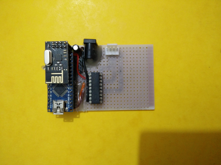
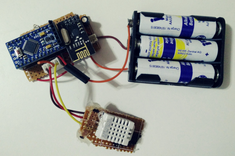
I have successfully hand built few nodes (2 based on Arduino Nano and 1 based on Arduino Pro Mini) and deployed around the home.
Here are some of the pictures of my nodes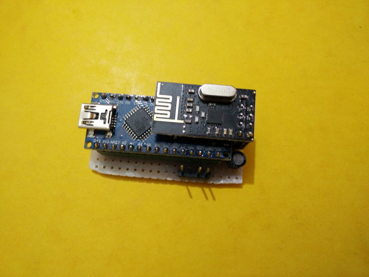
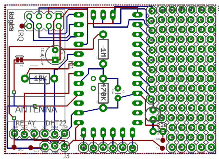
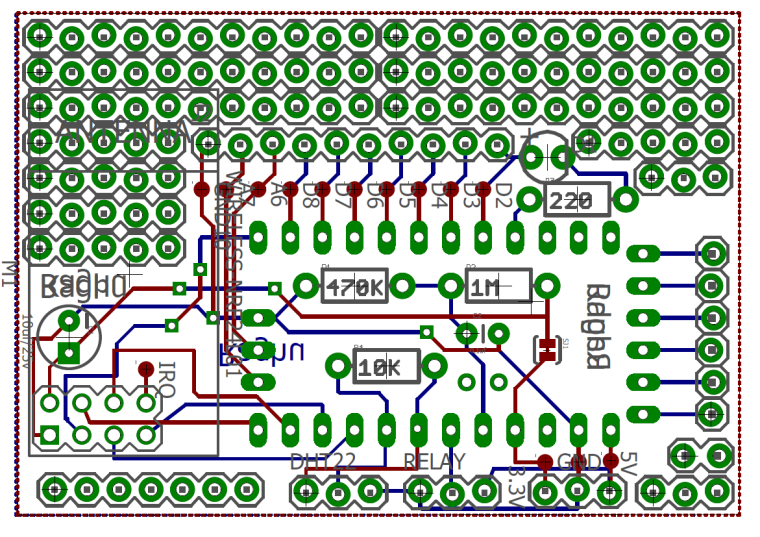
It takes lot of time to hand build these nodes. So I decided to make a small generic PCB uing Arduino Pro Mini and fabricate it and use it. I designed the PCB in Eagle SW and fabricated with Seedstudios.
Here is my board looks like
After mounting the components, I found it is not working. Tx/Rx was completely failure. After several hours of debugging, found that my circult is correct and I assume there were some EMC effects.
If I touch the antenna of nrf with my finger, Tx/Rx is successful and everything works perfect. If I remove my finger it does not work again.I thought because of placement of nrf module there were some EMC effects and created a V2 of my board by just changing position of nrf. It looks like this
Unfortunately, even this board/design has the same problem.
These are how the boards look like
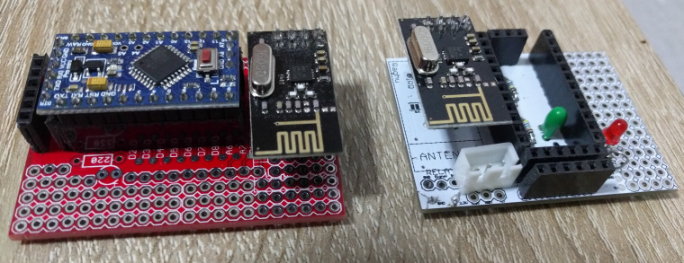
I also tried changing the position of nrf module by placing it in proto area and rewiring from the actual position, seems to have same problem.
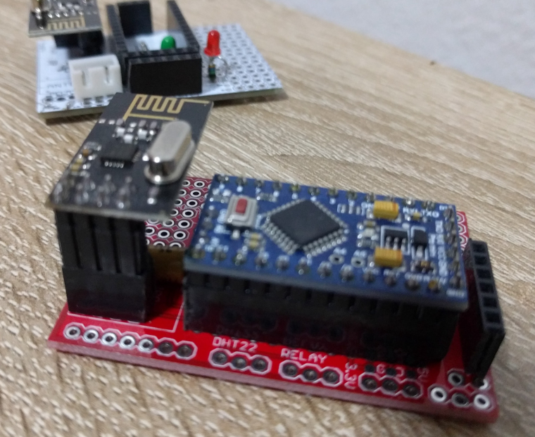
On both of these board when I lift the nrf module at higher level than the Arduino Pro by stacking additional female headers for nrf (as shown in below picture), they seem to be working.
Could some please help me understand whats happening on my board. :-( I want to go for V3 of board which solves these problem but I could not figure out what exactly is causing the problem.
Thank you so much for your support.
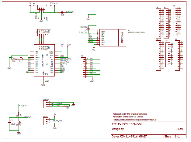
Unfortunately, I do not have privilege to upload board and schematic files, so I adding screenshots here.
@Raghavendra-Prasad Looks like interference between the radio module and and the pcb. Could also be a GROUND problem with your pcb (it works when you're touching the antenna).
First: remove the nrf from your pcb and reconnect with some jumper wires. Make sure the radio module is outside the pcb. If it works you have to redesign your pcb in such a way that the antenna is outside the pcb.
You could also try to shield your nrf (search the forum).
If it's still not working could you post your EAGLE files? (board and circuit file).
Success
-
Also the schematic would be helpful! Do you have equipment to check the air interface? (i.e. oscilloscope, spectrum analyzer)
Did you play with the power level of the nrf24?
-
@Raghavendra-Prasad Looks like interference between the radio module and and the pcb. Could also be a GROUND problem with your pcb (it works when you're touching the antenna).
First: remove the nrf from your pcb and reconnect with some jumper wires. Make sure the radio module is outside the pcb. If it works you have to redesign your pcb in such a way that the antenna is outside the pcb.
You could also try to shield your nrf (search the forum).
If it's still not working could you post your EAGLE files? (board and circuit file).
Success
@HarryDutch Thanks for the reply. I think if I remove nrf and keep away from board it will definetly work. As shown in one of the pictures above when I put the NRF little higher than Arduio, it works flawless. I tried to share the board and schematic files, but I could not upload seems I do not have privilege to upload them. If there special way to upload .brd and .sch files ?
-
Also the schematic would be helpful! Do you have equipment to check the air interface? (i.e. oscilloscope, spectrum analyzer)
Did you play with the power level of the nrf24?
-
@pansen Thanks for reply. I tried to upload the .sch file could got some error, so I added schematic screenshot. I do not have a sophisticated equipment, but I can manage to use a oscilloscope from my office.
@RaPo try different capacitors on the radio from VCC to GND and also try to make a wire from ground on different places like radio and arduino to source ground and see if that helps and when.
Your pinheaders might also be the problem... sometimes they are not that good quality. Same thing if you solder everything directle to the board?
-
@RaPo try different capacitors on the radio from VCC to GND and also try to make a wire from ground on different places like radio and arduino to source ground and see if that helps and when.
Your pinheaders might also be the problem... sometimes they are not that good quality. Same thing if you solder everything directle to the board?
@sundberg84 I will give a try to source the groung from Arduino. I also had same doubt about the headers, so I tried headers of different qualities. So, I hope headers are good, nevertheless I will try to solder directly.
-
Hmmm looks good, very strange indeed. Is it maybe the ground plane? A problem with your gateway?
-
Unfortunately I am not a PCB designer..I would advise you to ask this question (and also why the boards does not work) on a dedicated electronics forum. EEVBlog forums are very good for that purpose.
Good luck!P.S.: I guess you also tried different nrf24 boards right?
-
@HarryDutch Thanks for the reply. I think if I remove nrf and keep away from board it will definetly work. As shown in one of the pictures above when I put the NRF little higher than Arduio, it works flawless. I tried to share the board and schematic files, but I could not upload seems I do not have privilege to upload them. If there special way to upload .brd and .sch files ?
@RaPo You can zip your .brd and .sch files and upload the zip file.
-
Hi.
I'm thinking like others..for bad antenna orientation regarding your pcb. Sometimes this can work, but it adds noise to your radio.. what makes me think is on your pic you place it a little bit more above then it works.. the @sundberg84 notes can be interesting to check too ;)
Not really needed here, because you've only one thing on SPI bus, but it's good practice to have a pullup on CS line, to be sure to enable SPI periph only when needed. but not mandatory here sure!
For a battery powered node, i would better use a si7021 than dht22 ;) you can find si7021 breakout board at ali for a reasonable cost, and you'll definitely get a better battery lifetime.
And don't forget the resistor divider for batt voltage will consumes power. If directly powered from battery, you can simply use the VCC lib to read the voltage, or in other case (with any kind of reg) would need a mosfet to switch off your resistor divider.Keep the good work, you'll get it i'm sure :+1:
-
Hello all,
I am quite new to this form. I really like the idea of using small nrf24l01+arduino nodes around the home to control electronics.
I have successfully hand built few nodes (2 based on Arduino Nano and 1 based on Arduino Pro Mini) and deployed around the home.
Here are some of the pictures of my nodes
It takes lot of time to hand build these nodes. So I decided to make a small generic PCB uing Arduino Pro Mini and fabricate it and use it. I designed the PCB in Eagle SW and fabricated with Seedstudios.
Here is my board looks like
After mounting the components, I found it is not working. Tx/Rx was completely failure. After several hours of debugging, found that my circult is correct and I assume there were some EMC effects.
If I touch the antenna of nrf with my finger, Tx/Rx is successful and everything works perfect. If I remove my finger it does not work again.I thought because of placement of nrf module there were some EMC effects and created a V2 of my board by just changing position of nrf. It looks like this
Unfortunately, even this board/design has the same problem.
These are how the boards look like
I also tried changing the position of nrf module by placing it in proto area and rewiring from the actual position, seems to have same problem.
On both of these board when I lift the nrf module at higher level than the Arduino Pro by stacking additional female headers for nrf (as shown in below picture), they seem to be working.
Could some please help me understand whats happening on my board. :-( I want to go for V3 of board which solves these problem but I could not figure out what exactly is causing the problem.
Thank you so much for your support.
Unfortunately, I do not have privilege to upload board and schematic files, so I adding screenshots here.
@RaPo I think all the conductive material near the antenna absorbs/blocks the radio signal. That's why you get a better signal when the nrf is put on taller headers. Let the antenna stick out over the side of the board or make sure there is a sufficiently large area without any connections around the antenna. I do not know how much is considered sufficient though.
-
Unfortunately I am not a PCB designer..I would advise you to ask this question (and also why the boards does not work) on a dedicated electronics forum. EEVBlog forums are very good for that purpose.
Good luck!P.S.: I guess you also tried different nrf24 boards right?
-
Hi.
I'm thinking like others..for bad antenna orientation regarding your pcb. Sometimes this can work, but it adds noise to your radio.. what makes me think is on your pic you place it a little bit more above then it works.. the @sundberg84 notes can be interesting to check too ;)
Not really needed here, because you've only one thing on SPI bus, but it's good practice to have a pullup on CS line, to be sure to enable SPI periph only when needed. but not mandatory here sure!
For a battery powered node, i would better use a si7021 than dht22 ;) you can find si7021 breakout board at ali for a reasonable cost, and you'll definitely get a better battery lifetime.
And don't forget the resistor divider for batt voltage will consumes power. If directly powered from battery, you can simply use the VCC lib to read the voltage, or in other case (with any kind of reg) would need a mosfet to switch off your resistor divider.Keep the good work, you'll get it i'm sure :+1:
-
@RaPo I think all the conductive material near the antenna absorbs/blocks the radio signal. That's why you get a better signal when the nrf is put on taller headers. Let the antenna stick out over the side of the board or make sure there is a sufficiently large area without any connections around the antenna. I do not know how much is considered sufficient though.
@mfalkvidd Thanks for the hints. I will definitely consider this in my design.
-
Hi you are welcome to copy my design
https://www.openhardware.io/view/56/Mys-Interposer-NRFArduino-Pro-Mini -
Hello all,
Thank you so much for all your kind support. From a review from one my colleague, I learned that 90 degree sharp bends should be avoided. These sharp edges acts as local antenna and EMC interference. Unfortunately, my design has several of such sharp bends.