Sonoff Basic Wifi Gateway for NRF24
-
INTRODUCTION
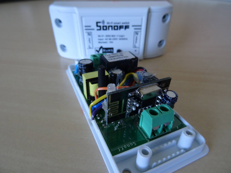
I recently bought some Sonoff Basic switches and was thinking how I could get the most out of its potential. As the Sonoff is mains powered and does not go to sleep, it is the ideal candidate to act as a (secondary) MySensors gateway or repeater for those remote battery powered nodes which have poor reception.
My first starting point was the MySensors website showing the Sonoff Relay. This page describes how to enable the Sonoff Relay in the MySensors framework as an ethernet gateway, but it does show how to enable it as a gateway or repeater for other MySensor nodes by for instance adding a NRF24 radio (the code example is already prepared, but there are conflicting pins as the GPIO used by the Sonoff overlaps with that of the MISO line for the radio).As I did not find anyone else who had yet described this "hack" I thought I would give it a go.
Wiring Things Up
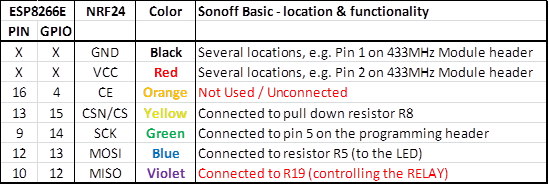
As the Sonoff Basic is based on the ESP8266 we only need to locate the correct pinning of the HSPI to which we can connect the radio. Unfortunately the MISO line in the Sonoff is used to switch the relay and the default CSN/CS line can only be reached on the ESP8266 package.So an overview of the SPI lines on the Sonoff:
Possible Solutions:
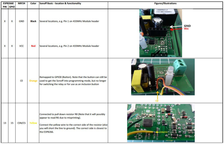
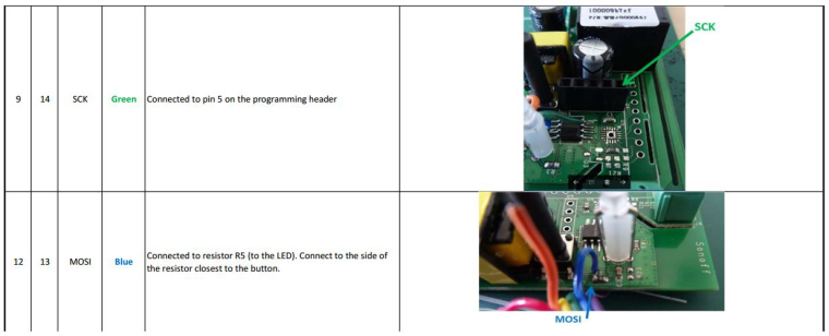
- The CSN/CS line can be remapped to any other available GPIO pin. An easily available GPIO is GPIO0 connected to the button. Note that the button can still be used to get the Sonoff into programming mode, but can no longer be used to switch the relay or as inclusion button. Other options could be the RX or TX pins on the programming header.
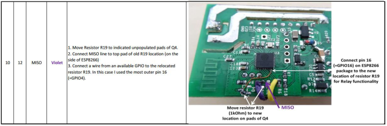
- The MISO line is no problem if you have no need for the relay and you can simply remove resistor R19. If you do need the relay, then you either have to solder a wire directly to the ESP8266 or use one of the RX/TX pins on the programming header.
I choose the option to directly solder to the ESP8266 package and did not test the option of using the RX and TX pins on the programming header as I wanted to keep them available for debugging purposes at this moment in time.
Tested wiring in detail
Sketch adaptations
I used the Sonoff Relay example on the MySensors website as a default and changed the following parts:- Enabled the radio:
#define MY_RADIO_NRF24 - Disabled the Inclusion mode feature:
//#define MY_INCLUSION_MODE_FEATURE - Disabled the LED indicators:
//#define MY_DEFAULT_ERR_LED_PIN 16 // Error led pin
//#define MY_DEFAULT_RX_LED_PIN 16 // Receive led pin
//#define MY_DEFAULT_TX_LED_PIN 16 // the PCB, on board LED - Remapped the SPI CE pin:
#define MY_RF24_CE_PIN 0 //Using the button GPIO-0 as CE for the nRF24 radio - Remapped the Relay pin:
#define RELAY_PIN 4 // Using pin16 on ESP8266 (=GPIO-4) to control the Relay - Removed the button related stuff
- Removed the LED related stuff (e.g. blink)
- Empty the void loop (as we no longer trigger the relay with the button)
Additional Tests
- The node was also tested with soft signing and works correctly. For soft signing you need the unconnected analog pin which is:
#define MY_SIGNING_SOFT_RANDOMSEED_PIN A0 //!< Unconnected analog pin for random seed
-
@Technovation Welcome to the MySensors forum!
This is an awesome first post!
Hope to see a lot more in the future!
