Battery life for Motion Sensor
-
And use 2xAA instead of 9v 👍
@sundberg84 Noted. Thanks:ok_hand:
-
There are also am 312 pir sensors that work at 3.3v, but the have some blind spots. Or just buy the xiaomi gateway and motion sensors if you don't want to modify things, since making something battery friendly means removing all those components that consume energy.
-
You can also use 3 AA batteries in a configuration like this:
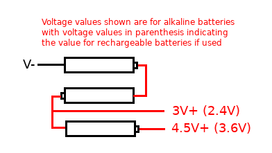
I have noted values for rechargeable batteries as these have a nominal value of 1.2 volts vs 1.5 volts for an alkaline battery. The 4.5v side would be to power the PIR and the 3V side to power the pro mini.
-
There are also am 312 pir sensors that work at 3.3v, but the have some blind spots. Or just buy the xiaomi gateway and motion sensors if you don't want to modify things, since making something battery friendly means removing all those components that consume energy.
-
@gohan Thanks for the info, but I would like to build my own sensors. So i'll study the Pro Mini on 3.3V further.
@popsyann and get yourself a good current meter. It is almost imposible to make low power node without the current meter.
-
@popsyann and get yourself a good current meter. It is almost imposible to make low power node without the current meter.
@rozpruwacz What do you mean by "good current meter"? Can you be a bit more specific? Have some knowledge of electricity and electronics domain but that does not ring a bell to me. Thanks in advance for your answer.
-
You can also use 3 AA batteries in a configuration like this:
I have noted values for rechargeable batteries as these have a nominal value of 1.2 volts vs 1.5 volts for an alkaline battery. The 4.5v side would be to power the PIR and the 3V side to power the pro mini.
@dbemowsk Thank you for the info. I have made some progress and I have one sensor working on Pro Mini, with 2 x AA batteries. I am facing an issue with radio range. Apparently everything works well within close range but if I put the sensor some 8-10 meters from the gateway, I do not have accurate update of the sensor state (on-off). I though the NRF24 was able to cover such range.....
-
@dbemowsk Thank you for the info. I have made some progress and I have one sensor working on Pro Mini, with 2 x AA batteries. I am facing an issue with radio range. Apparently everything works well within close range but if I put the sensor some 8-10 meters from the gateway, I do not have accurate update of the sensor state (on-off). I though the NRF24 was able to cover such range.....
@popsyann Poor RF issues can be a sign power issues (GW) or an indication of a low quality nrf24l01+
I have 3 PIRs. One of them have been working for 1.5 years on 2xAA batteries (Arduino Pro Mini modified + nrf24l01+). Some nodes are very remote from the gateway.
-
@popsyann Poor RF issues can be a sign power issues (GW) or an indication of a low quality nrf24l01+
I have 3 PIRs. One of them have been working for 1.5 years on 2xAA batteries (Arduino Pro Mini modified + nrf24l01+). Some nodes are very remote from the gateway.
@alexsh1 Hi, maybe you can help me with the following:
I have built motion sensors with Arduino mini 3.3V and they have been working well, integrated in Home Assistant. However, the battery life is far from being satisfactory (I am looking for at least a year, and currently I reach a month, at most).
While replacing batteries, I have discovered (because the sensor was not working well after battery replacement) that the sensor component works well (3V when motion detected, 0V when no motion) when not connected to the Arduino Mini. As soon as I connect the output to pin 3 (as defined in the sketch), I get 3V when there is motion, and 1.1V when no motion (which results in no status update). Do you have any clue on what could be the reason of this 1.1V once connected (instead of 0V with no motion)?
Help appreciated.
-
@alexsh1 Hi, maybe you can help me with the following:
I have built motion sensors with Arduino mini 3.3V and they have been working well, integrated in Home Assistant. However, the battery life is far from being satisfactory (I am looking for at least a year, and currently I reach a month, at most).
While replacing batteries, I have discovered (because the sensor was not working well after battery replacement) that the sensor component works well (3V when motion detected, 0V when no motion) when not connected to the Arduino Mini. As soon as I connect the output to pin 3 (as defined in the sketch), I get 3V when there is motion, and 1.1V when no motion (which results in no status update). Do you have any clue on what could be the reason of this 1.1V once connected (instead of 0V with no motion)?
Help appreciated.
@popsyann
In your sketch, please check that you have defined the input pin for the PIR pin as pinMode (PIR_PIN, INPUT) and not pinMode (PIR_PIN, INPUT_PULLUP). If you have activated the internal pullup in the arduino this will prevent the PIR from pulling the input low when there is no motion. -
@popsyann you have to provide more info :
- did you modify arduino pro mini for batteries life?
- what PIRs do you have?
- post your sketch please
Hi
- I did not modify the Arduino Pro Mini for Batteries life. What is there that I should do? Did not read anything about it.
- I use either the standard PIR Motion sensor (with two potentiometers on board the module to adjust sensitivity and timer) (Seems to be HC-SR501), or the mini version of this sensor .
- The code I use is the one given in the MySensors
/** * The MySensors Arduino library handles the wireless radio link and protocol * between your home built sensors/actuators and HA controller of choice. * The sensors forms a self healing radio network with optional repeaters. Each * repeater and gateway builds a routing tables in EEPROM which keeps track of the * network topology allowing messages to be routed to nodes. * * Created by Henrik Ekblad <henrik.ekblad@mysensors.org> * Copyright (C) 2013-2015 Sensnology AB * Full contributor list: https://github.com/mysensors/Arduino/graphs/contributors * * Documentation: http://www.mysensors.org * Support Forum: http://forum.mysensors.org * * This program is free software; you can redistribute it and/or * modify it under the terms of the GNU General Public License * version 2 as published by the Free Software Foundation. * ******************************* * * REVISION HISTORY * Version 1.0 - Henrik Ekblad * * DESCRIPTION * Motion Sensor example using HC-SR501 * http://www.mysensors.org/build/motion * */ // Enable debug prints // #define MY_DEBUG // Enable and select radio type attached #define MY_RADIO_NRF24 //#define MY_RADIO_NRF5_ESB //#define MY_RADIO_RFM69 //#define MY_RADIO_RFM95 #include <MySensors.h> uint32_t SLEEP_TIME = 120000; // Sleep time between reports (in milliseconds) #define DIGITAL_INPUT_SENSOR 3 // The digital input you attached your motion sensor. (Only 2 and 3 generates interrupt!) #define CHILD_ID 1 // Id of the sensor child // Initialize motion message MyMessage msg(CHILD_ID, V_TRIPPED); void setup() { pinMode(DIGITAL_INPUT_SENSOR, INPUT); // sets the motion sensor digital pin as input } void presentation() { // Send the sketch version information to the gateway and Controller sendSketchInfo("Motion Sensor", "1.0"); // Register all sensors to gw (they will be created as child devices) present(CHILD_ID, S_MOTION); } void loop() { // Read digital motion value bool tripped = digitalRead(DIGITAL_INPUT_SENSOR) == HIGH; Serial.println(tripped); send(msg.set(tripped?"1":"0")); // Send tripped value to gw // Sleep until interrupt comes in on motion sensor. Send update every two minute. sleep(digitalPinToInterrupt(DIGITAL_INPUT_SENSOR), CHANGE, SLEEP_TIME); } -
- https://www.mysensors.org/build/battery
- OK
- This is a standard sketch. Cannot see anything wrong.
@alexsh1 Indeed, I saw the batteries life page but I did not want to cut into my Pro Minis (and I believe that the LED provides a good info as to the sensor is well powered).
Even if I make this modification, that does not explain the 3V to 1V instead of 3V to 0V phenomenon. Does it?
-
@alexsh1 Indeed, I saw the batteries life page but I did not want to cut into my Pro Minis (and I believe that the LED provides a good info as to the sensor is well powered).
Even if I make this modification, that does not explain the 3V to 1V instead of 3V to 0V phenomenon. Does it?
@popsyann I de-soldered power LEDs and power regulators. You do not need them for battery powered nodes and this is reversible. Otherwise you wont get low uA.
This is about power.Talking about voltage - did you measure it? How do you know if goes to 1V?
Did you double-triple check all wires and everything is correct?FYG - HR-SR501 has to be modified as well for 3.3V (remove regulator)
http://www.instructables.com/id/Convert-a-5v-PIR-Motion-Sensor-to-33v-for-ESP8266/ -
@popsyann I de-soldered power LEDs and power regulators. You do not need them for battery powered nodes and this is reversible. Otherwise you wont get low uA.
This is about power.Talking about voltage - did you measure it? How do you know if goes to 1V?
Did you double-triple check all wires and everything is correct?FYG - HR-SR501 has to be modified as well for 3.3V (remove regulator)
http://www.instructables.com/id/Convert-a-5v-PIR-Motion-Sensor-to-33v-for-ESP8266/@alexsh1 Noted for the de-soldering info. I get it.
For voltage measurements, yes I did measure the voltage between the ground and the output pin of the motion sensor: when the pin is not connected to Arduino, I get 3V when motion is detected and 0V when no motion.
Then I connect the output pin of the PIR to the Arduino (pin 3) and I measure on Arduino pin 3: I get 3V when motion is detected and 1.2V when no motion.
As for the modification of the PIR: noted. But I mainly use the mini PIR, where such modification cannot be applied (as the circuitry is very different and very simple).For the cabling: when I load on the Arduino the Serial Gateway sketch, everything works well, the Gateway starts properly, meaning the radio is well connected.
When I load the motion sensor sketch, it start properly, finding the right "parent" and immediately after this, there is a flow of info going out of the Arduino+sensor, sending 0s or 1s, constantly (like if there was an issue with the interrupt process).
And what I do not understand is that this (these) sensor(s) has(have) been working well for a while.
-
@alexsh1 Noted for the de-soldering info. I get it.
For voltage measurements, yes I did measure the voltage between the ground and the output pin of the motion sensor: when the pin is not connected to Arduino, I get 3V when motion is detected and 0V when no motion.
Then I connect the output pin of the PIR to the Arduino (pin 3) and I measure on Arduino pin 3: I get 3V when motion is detected and 1.2V when no motion.
As for the modification of the PIR: noted. But I mainly use the mini PIR, where such modification cannot be applied (as the circuitry is very different and very simple).For the cabling: when I load on the Arduino the Serial Gateway sketch, everything works well, the Gateway starts properly, meaning the radio is well connected.
When I load the motion sensor sketch, it start properly, finding the right "parent" and immediately after this, there is a flow of info going out of the Arduino+sensor, sending 0s or 1s, constantly (like if there was an issue with the interrupt process).
And what I do not understand is that this (these) sensor(s) has(have) been working well for a while.
@popsyann said in Battery life for Motion Sensor:
When I load the motion sensor sketch, it start properly, finding the right "parent" and immediately after this, there is a flow of info going out of the Arduino+sensor, sending 0s or 1s, constantly (like if there was an issue with the interrupt process).
And what I do not understand is that this (these) sensor(s) has(have) been working well for a while.
Please search for sleep() function - it has changed the way it works at some stage in MySensors 2.*
https://forum.mysensors.org/topic/1088/battery-powered-pir
https://forum.mysensors.org/topic/5807/interrupt-and-sleep/26
https://forum.mysensors.org/topic/5552/pin-change-interrupt-not-firing-with-mysensors/28Another reason could you that your PIR is not settling properly - this is why it sends out 1s and 0s to the GW. Try to insert sleep(20000); into void setup() at the end to settle the PIR