Battery powered PIR
-
This post outlines how to run a PIR sensor with 2xAA batteries and use interrupts to sleep a 3V3 8 MHz Arduino between both tripped and not-tripped states. This seems pretty straight forward, however there are a couple subtleties.
- The stock PIR is outfitted with a voltage regulator that requires ~4V5.
- Voltage ripple from the voltage booster (2xAA boost to 3V3) can cause certain sensitive sensors to reset and oscillate. Especially when entering sleep (SLEEP_MODE_PWR_DOWN), because of the large change in operating current. The reduction of the operating current, when entering sleep, will cause the booster to change frequency and magnitude of the output voltage ripple.
Here, I will describe how I overcame this problem by modifying the PIR to work at 3V0.
Steps:
PIR PCB modification
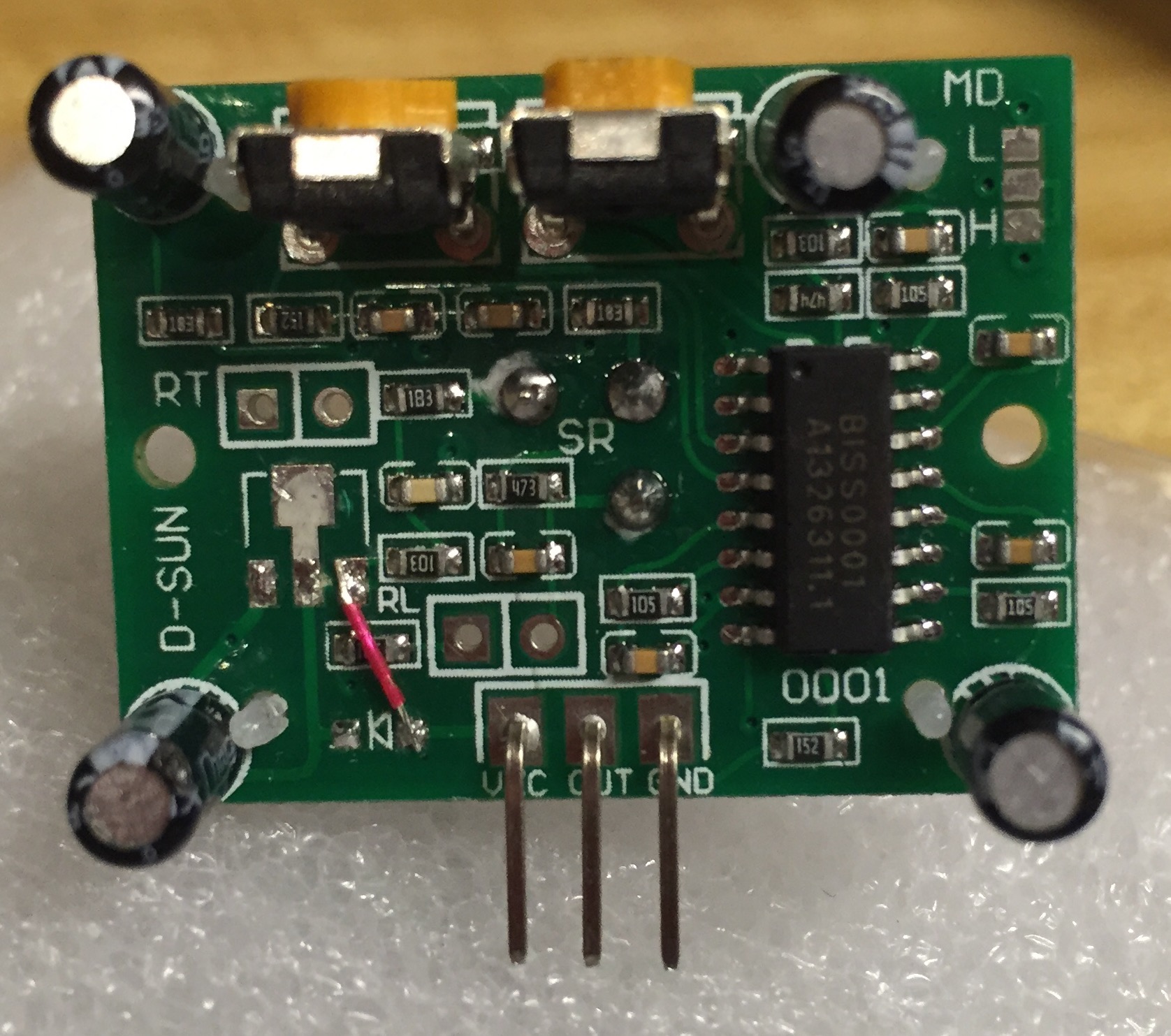
- Remove the voltage regulator and diode from the PIR PCB
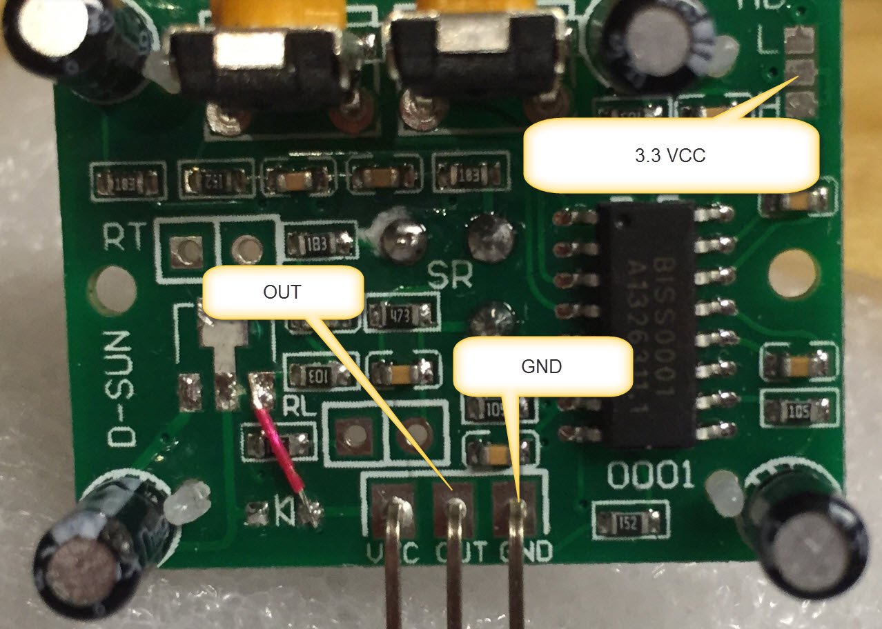
- Solder a wire (red wire in the photo) from the VCC pin to the former location of the output pin of the voltage regulator
The board should look like the photo shown below
Prepare the power source for the PIR
- The voltage from the 2xAA batteries (in my case) are boosted by a XC9140 low quiescent current 3V3 voltage regulator to power the Arduino pro mini. The radio is powered directly from the 2xAA batteries as it has its own regulator and can operate down to 1V9.
- The PIR sensor is based on the BISS0001 which as a supply voltage range of ~3-5 V. The modification done in earlier makes the module very sensitive to voltage ripple. In fact, the voltage ripple that occurs when switching from an awake to sleeping Arduino is enough, I believe, to cause the BISS0001 to reset and either oscillate or freeze.
- I investigated a couple of solutions, but the best is to use a low-drop-out-voltage high-ripple-rejection-ratio regulator (FT531IA, 3V0, 36 µA supply current) to reduce the 3V3 boosted high-ripple supply to a steady 3V0. I know this seems silly to boost and then regulate down to another voltage but the data speaks for itself, below.
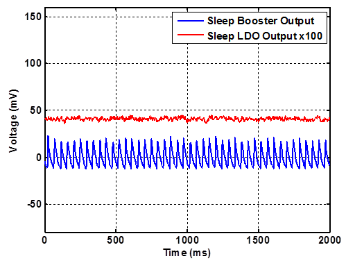
Figure 1. Comparison of the output of the 3V3 booster and the LDO 3V0 regulator while the Arduino is sleeping. AC coupled scope termination. Note: the LDO is multiplied by 100 and offset for clarity.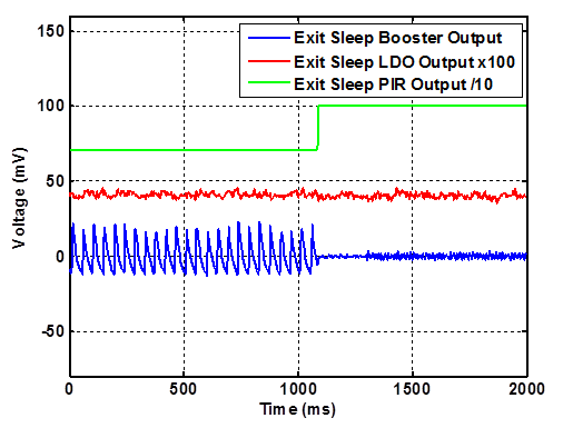
Figure 2. Motion at around 1100 ms causes the PIR output to go high and the Arduino to wake up. Note the output from the booster quiets down and the output from the LDO is smooth. PIR and LDO outputs are offset for clarity.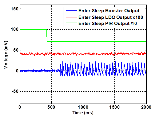
Figure 3. Entering sleep once the PIR goes from tripped to non-tripped state. Once the Arduino starts to sleep, the output from the booster becomes noisy, while the LDO is smooth. PIR and LDO outputs are offset for clarity.Here is my example code (nothing fancy and much of it is borrowed from various places).
//This program will test the PIR using interrupts
#include <avr/sleep.h>
#include <avr/interrupt.h>


void setup()
{
Serial.begin(115200);
pinMode(3,INPUT);
digitalWrite(3, LOW);
pinMode(4,OUTPUT);
//Signal PIR startup by flashing an LED
digitalWrite(4,HIGH);
delay(5000);
digitalWrite(4,LOW);
delay(200);
}

void loop()
{
  //Come out of sleep and read state of PIR pin
  bool flag = digitalRead(3);
  if (flag == true)
  {
    Serial.println("tripped");
    digitalWrite(4,HIGH);
  }
  else
  {
    Serial.println("not tripped");
    digitalWrite(4,LOW);
  }
  delay(100);
  sleepNow();
}

void sleepNow()
{
    Serial.println("Entering Sleep");
    // Set pin 3 as interrupt and attach handler:
        attachInterrupt(1, wakeUp, CHANGE);
        delay(100);
        // Choose our preferred sleep mode:
        set_sleep_mode(SLEEP_MODE_PWR_DOWN);

    // Set sleep enable (SE) bit:
    sleep_enable();

// Put the device to sleep:
sleep_mode();

// Upon waking up, sketch continues from this point.
sleep_disable();
}

void wakeUp(void)
{
    detachInterrupt(1);
}
One last thing, it is necessary to attach a pull-down resistor on the PIR output pin in order to help the signal line go low when transitioning to the non-tripped state.
-
You dont Need to Strip the voltage Regulator from the board. Just use the marked solder pad to feed the board with 3.3. This works fine for me.
-
What is downside to instead using 3xAA and a good LDO regulator with a modified sensor?
This way you dont get any ripple and dont need any step up booster. -
@therik
Nice work! Do you know the overall sleep mode power/current? And what battery life time one can expect from a real application?
@Andreas-Maurer
If you leave the regulator, isn't there the a power draw from the reverse feeding like with the Arduino pro minis?
@Mrlynx
Which LDO do you have in mind? Maybe the battery economy would be a little worse as well. At least with 3AAs and >500mV drop-out.. -
So, I'm quite a rookie when it comes to electronics, but I made the 3.3V modification to this PIR sensor too. I had trouble with stability as well when I removed the voltage regulator and the diode, so I removed the two capacitors from the bottom (one 47uF, and the other 22uF) that I assumed are the buffers on both sides of the voltage regulator. Now the sensor is fed directly from my 3.3V step-up converter (based on NCP1402SN33T1) and it's very reliable and stable.
I have 2 of these sensors connected to the two interrupt pins and my sensor is going strong since 2 weeks on a single AAA NiMH battery (750mAh). I think it has at least another 2 weeks in it.
I'm using these to trigger the lights in my entrance room, so I'd notice if they wouldn't work. The board also wakes up every minute to send the battery voltage and I don't see unusual wakeups or unresponsiveness.
-
@darazs Good to know. I think the output of the booster is very dependent on the current draw and, of course, every booster is a little different.
@therik Yeah, now that I've read through your "Efficiency of Voltage Boosters" topic, I understand things a little better, and I really have no clue why removing the caps made the PIR more stable. BUT your topic helped me solve my packet loss/acks not arriving problem by adding a bigger capacitor to my radio, so what I want to say is that you're awesome, thanks! :)
-
@m26872 I am looking at xc6206 and tc2117 that have a low quiescent current and a dropout of 50-100 mV at low currents.
@therik I recently observed the same behaviour with a step-up regulator based on a 2108A.
The strange thing is that the sensor behaves erratic when powered from 2 fresh AA alkaline batteries (approx. 3.2V input to the regulator) but works just fine when powered by some older AA alkaline batteries (approx. 2.6V input).
I quickly inspected the output of the regulator with a scope, but saw no clear differences between the two. Maybe the output was less stable at 3.2V input.
Next I'll try using a diode to lower the voltage a little, either before or after the regulator. -
I am trying to figure out if running this modification from 3 AAs at 4.5V will work (it is for a setup with a attiny85 that I want to run from 4.5 down to 3.3v - it currently works well from 5 down to 4.5 with exactly the erratic behaviour explained above from about 4.4v and down). When looking at the datasheet for the BIS0001 then it seems like it will fine? What am I missing? :)
-
A couple of questions.
- Did you remove the voltage regulator from the PIR?
a. if not, I would suspect that the voltage regulator on the PIR drops out and cannot supply the voltage for the PIR IC below 4V5. - Where do you derive the power for the PIR?
a. If it is from the µC, the µC may be adding noise on the voltage supply to the PIR and with the PIR voltage regulator removed the supply voltage may be too noisy.
- Did you remove the voltage regulator from the PIR?
-
The regulator was not removed yet, no, the behaviour was with my unmodified sensor. I have actually now started looking at an alternative power setup so that i can use this mod at 3.3v and drop the requiment for it to run from 4.5v (which was based on running it upregulated from 3 AAs with an attiny85 woken up from sleep mode - which worked well and consumed ~0.1mA overall). Back to the drawing board :)
-
How did you produce that nice ripple charts? Oscilloscope connected to a computer? What is the model?
-
Thanks for sharing, @therik. Where can I get the high-ripple-rejection-ratio regulator you are describing? I cannot find an FT531IA on Ebay. (Or if therik is no longer following the topic: Anyone else know a specific regulator I gan get from Ebay?)
Thanks in advance.
-
It's still on aliexpress. Could a AMS1117 work too though? It's ripple rejection isn't bad for what I have read. Although I don't get the part of the specs.. if you use a fixed version do you still need a capacitor on the GND (adj) pin for the ripple rejection?
-
It's still on aliexpress. Could a AMS1117 work too though? It's ripple rejection isn't bad for what I have read. Although I don't get the part of the specs.. if you use a fixed version do you still need a capacitor on the GND (adj) pin for the ripple rejection?
Thanks, @LastSamurai! I have ordered a few to try them out. (Not sure about the question about AMS1117, hopefully there are someone here who are.)
Hello! It looks like you're interested in this conversation, but you don't have an account yet.
Getting fed up of having to scroll through the same posts each visit? When you register for an account, you'll always come back to exactly where you were before, and choose to be notified of new replies (either via email, or push notification). You'll also be able to save bookmarks and upvote posts to show your appreciation to other community members.
With your input, this post could be even better 💗
Register Login