Efficiency of Voltage Boosters
-
Well, I thought I would re-post the data and try to summarize the thread that was lost.
Objective: Run a sensor node for a year on batteries. Wake period ~2 - 5 minutes.
Approach: Use a voltage step-up converter to boost the voltage from 1 or 2 AA batteries to 3.3 V or 5 V required by the two flavors of pro-mini clones.
Problem: Even though folks have discovered methods to put the sensor node into a deep sleep mode which draws ~100 - 200 microA; the efficiency of the step-up modules prevent realization of such a low current draw; rather, at that low current draw the efficiency of the step-up converters yields ~1-2 mA. See figures,
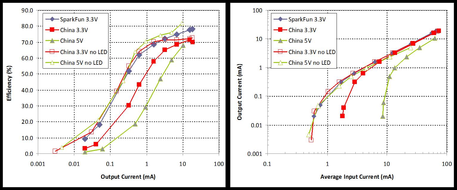
The good news here is that the cost efficient step-up converters from China are just as efficient as the SparkFun NCP1402 when the LED is disabled.
Solution: The search was on to find a more power efficient step-up converter. Here are some that I and other folks found.
TPS61222 - These are pretty small though.
TPS61097 - These are sort of expensive.
XC9140AXX1 - These look promising.
SC120 - Also cost effective, but may not be as efficient as the above.I have ordered the parts to construct boosters using the TPS61097-33 and XC9140A331 and will report back to the forum with the results.
Everyone - does that summarize the original post sufficiently?
-
Holds the text of the old posts:
-
Holds the text of the old posts:
-
Nice summary. I'd like to add the booster chip that axillent was using for his project, the MCP1640.
Also, since this project is utilizing radio communication, both EMI and the quality of the boosted power could be an issue. There were some other post, probably gone now, that talked about connecting batteries directly and separately to the radio to get around such issues. Probably had something to do with ebay regulators or the regulator on the arduino?
Looking forward to more test results. Don't forget to mention what brand / type of inductor and capacitors you go for in the circuits.
-
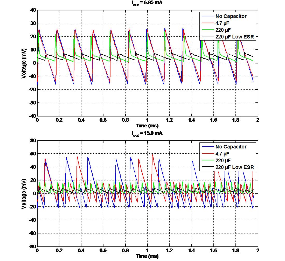
The tests recorded the radio supply Voltage under various conditions and demonstrated that a low ESR (Equivalent Series Resistance) capacitor gave the best results. It seemed highly likely that the other capacitors tested were plain old electrolytics? They are not suitable for use as decoupling capacitors for the radio. Either tantalum or aluminum polymer capacitors should be used, as they typically have the desirable characteristic of a low ESR value. They should be mounted physically at the radio and wired between the power pins - plus and ground. Their leads should be as short as possible. Any oscilloscope measurements should have the probe connected directly across the capacitor. A couple of the tests used 220 uF caps, perhaps a little unnecessarily large. A lower value of 47 uF should be adequate.
It was suggested that the cleaner power supply Voltage may have reduced electromagnetic interference (EMI) at the radio receiver. This may be the case but I'm inclined to think that it just improves the operation of the receiver IC itself. Either way, a clean power supply that has a bit of grunt when needed, is always a good thing.
Hope I have remembered this correctly.
-
The tests recorded the radio supply Voltage under various conditions and demonstrated that a low ESR (Equivalent Series Resistance) capacitor gave the best results. It seemed highly likely that the other capacitors tested were plain old electrolytics? They are not suitable for use as decoupling capacitors for the radio. Either tantalum or aluminum polymer capacitors should be used, as they typically have the desirable characteristic of a low ESR value. They should be mounted physically at the radio and wired between the power pins - plus and ground. Their leads should be as short as possible. Any oscilloscope measurements should have the probe connected directly across the capacitor. A couple of the tests used 220 uF caps, perhaps a little unnecessarily large. A lower value of 47 uF should be adequate.
It was suggested that the cleaner power supply Voltage may have reduced electromagnetic interference (EMI) at the radio receiver. This may be the case but I'm inclined to think that it just improves the operation of the receiver IC itself. Either way, a clean power supply that has a bit of grunt when needed, is always a good thing.
Hope I have remembered this correctly.
@a-lurker Hmm. Perhaps the store shouldn't recommend electrolytic capacitors then for the radio decoupling.
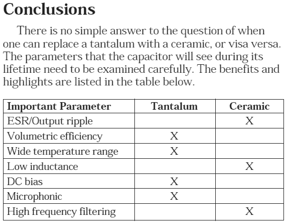
Comparison between tantalum and ceramic capacitors:
http://www.avx.com/docs/techinfo/mlc-tant.pdfPertinent conclusion table:
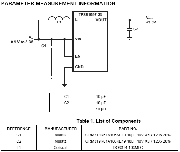
Texas Instruments recommends (fancy SMD) ceramic capacitors for the TPS61097 and TPS6122x. Empirical evidence would suggest that cheap Ebay caps may not be the best idea. Nor would it be prudent to replace them with Tantalum, though that could also be attributed to cheap Ebay goods. The post is unclear on this.
From the TI datasheet on the TPS61097:
-
What about being able to turn on / off the voltage regulator via output pin and mosfet and powering the arduino from a cap while in standby? and in awake mode it turns on regulator and charges up the cap again.
-
@a-lurker Hmm. Perhaps the store shouldn't recommend electrolytic capacitors then for the radio decoupling.
Comparison between tantalum and ceramic capacitors:
http://www.avx.com/docs/techinfo/mlc-tant.pdfPertinent conclusion table:
Texas Instruments recommends (fancy SMD) ceramic capacitors for the TPS61097 and TPS6122x. Empirical evidence would suggest that cheap Ebay caps may not be the best idea. Nor would it be prudent to replace them with Tantalum, though that could also be attributed to cheap Ebay goods. The post is unclear on this.
From the TI datasheet on the TPS61097:
@bjornhallberg said:
@a-lurker Hmm. Perhaps the store shouldn't recommend electrolytic capacitors then for the radio decoupling.
Yep, we should probably do that. Need help finding a good candidate. Found this. Any good?
Search: "tantalum 47uf -smd"
-
Yes, you got the result from the booster voltage ripple test correct, the 4.7 microF is the one recommended from the MySensors store, and the other 220 microF is a high-end audio electrolytic. The low ESR is here. Here is the data,
Now, with that being said; why power the radio from the booster at all? I would submit, for battery powering a sensor node, that one should simply connect the radio directly to the battery (2xAA). The Arduino seems to be less sensitive, but still need to test. Connecting the battery directly also is more efficient, no power loss through the booster.
My observation was, at a range of ~few feet, that I would get ~20-70% radio communication fails in the 'pingpair' sketch with the radio powered by the booster, and 100% success radio powered from 2xAA batteries, and 100% success radio powered by booster with the low ESR capacitor mentioned above. I didn't have any lower capacitor values to test (actually, I think I might have a 150 microF as well, but no lower values).
I also tested the 5 V -to- 3 V step-down regulator from the MySensors store and that is dead flat, no voltage ripple (~1-2 mV noise). But, that is also power inefficient, however it is a good option for a plug-in node or gateway.
-
So, you are saying that it looks like there is no capacitor or anything else needed when powering the radio separately?
And, when using a capacitor the 220 microF is better in any case (good or less quality)?
-
Nice summary. I'd like to add the booster chip that axillent was using for his project, the MCP1640.
Also, since this project is utilizing radio communication, both EMI and the quality of the boosted power could be an issue. There were some other post, probably gone now, that talked about connecting batteries directly and separately to the radio to get around such issues. Probably had something to do with ebay regulators or the regulator on the arduino?
Looking forward to more test results. Don't forget to mention what brand / type of inductor and capacitors you go for in the circuits.
@bjornhallberg said:
Looking forward to more test results. Don't forget to mention what brand / type of inductor and capacitors you go for in the circuits.
I'm currently doing tests with prototype of future MySensors board.
It is started today from a single AA battery.
The radio part is not yet soldered but will be soldered as soon as I will compile and test a correct bootloader -
As for capacitors.
Do not mix different things.old-style electrolitic and tantalum can be used to decouple radio module power.
this capacitor is needed to reduce drop of the voltage at a time of receiving and sendingas for step-ups/step-downs/LDO there is no ideal capacitor in general. You should always refer to the recommendations from the datasheet.
Most modern power chips are required multil-layers ceramic capacitors. Such capacitors they have stable characteristics and very low ESR (much lower than tantalum have). In most cases it is X7R or X5R (the difference between this two is temperature stability)
But for some power chips ceramic will be not recommended. Refer to the datasheet. -
So, you are saying that it looks like there is no capacitor or anything else needed when powering the radio separately?
And, when using a capacitor the 220 microF is better in any case (good or less quality)?
-
I've (perhaps naively) built my battery powered MySensors pcb's around the 3 pin configuration of the ebay cheapie. If many others have done the same then I can see some value in someone creating a drop-in replacement board based on the more efficient chips. I'd definitely buy the more efficient version if someone created it, whether pre-made or solder-it-yourself.
-
Good to see new activity on this thread again.
@axillent Unless there is some EMI coupled into the power leads of a battery connected radio, or current draw from the battery can't keep up with demand, I don't see why a capacitor is needed. In fact, the product brief for the nRF24L01+ states that it is designed with an on-board voltage regulator and permits operation with a coin-cell battery. Is there something I'm missing?
Also, regarding capacitors, I think you mean 220 microF is 'overkill' or 'more-than-enough', rather than 'too-much'. Right?
Anyway, here is a comparison of aluminum polymer capacitors of different capacitance. Note how the 220 microF cap is cheaper and has lower ESR than either the 10 microF or the 47 microF, and is only slightly larger in physical size.
Tantalum on the other hand has a quite high ESR, on the order of ohms, not good for suppressing voltage ripple according to this document.
That being said, ceramics may be the way to go for sub-100 microF as they are lower cost, smaller, and very low ESR; above 100 microF ceramics get very expensive, ~$4 for a 220 microF.
-
I've (perhaps naively) built my battery powered MySensors pcb's around the 3 pin configuration of the ebay cheapie. If many others have done the same then I can see some value in someone creating a drop-in replacement board based on the more efficient chips. I'd definitely buy the more efficient version if someone created it, whether pre-made or solder-it-yourself.
@Bandra Great, would you be able to share your run times so that we can get some real world data? That is, how long can you run a node before the battery is discharged?
I was thinking about making a board using one of the high efficiency boosters listed in the first post, if they prove their worth. I get my components in on Saturday, so sometime next week I should have preliminary results.
-
Good to see new activity on this thread again.
@axillent Unless there is some EMI coupled into the power leads of a battery connected radio, or current draw from the battery can't keep up with demand, I don't see why a capacitor is needed. In fact, the product brief for the nRF24L01+ states that it is designed with an on-board voltage regulator and permits operation with a coin-cell battery. Is there something I'm missing?
Also, regarding capacitors, I think you mean 220 microF is 'overkill' or 'more-than-enough', rather than 'too-much'. Right?
Anyway, here is a comparison of aluminum polymer capacitors of different capacitance. Note how the 220 microF cap is cheaper and has lower ESR than either the 10 microF or the 47 microF, and is only slightly larger in physical size.
Tantalum on the other hand has a quite high ESR, on the order of ohms, not good for suppressing voltage ripple according to this document.
That being said, ceramics may be the way to go for sub-100 microF as they are lower cost, smaller, and very low ESR; above 100 microF ceramics get very expensive, ~$4 for a 220 microF.
@axillent Unless there is some EMI coupled into the power leads of a battery connected radio, or current draw from the battery can't keep up with demand, I don't see why a capacitor is needed. In fact, the product brief for the nRF24L01+ states that it is designed with an on-board voltage regulator and permits operation with a coin-cell battery. Is there something I'm missing?
I'm not an EMI or decoupling freak but I knew from practice own and others that communication distance is very vary with and without capacitor soldered very close to the radio.
You can try yourself. My PA+LNA modules are having tantalum soldered near power pins while cheap $1 modules do not have a capacitor on board -
@axillent Unless there is some EMI coupled into the power leads of a battery connected radio, or current draw from the battery can't keep up with demand, I don't see why a capacitor is needed. In fact, the product brief for the nRF24L01+ states that it is designed with an on-board voltage regulator and permits operation with a coin-cell battery. Is there something I'm missing?
I'm not an EMI or decoupling freak but I knew from practice own and others that communication distance is very vary with and without capacitor soldered very close to the radio.
You can try yourself. My PA+LNA modules are having tantalum soldered near power pins while cheap $1 modules do not have a capacitor on board@axillent I totally agree with the radio being very sensitive to noise and voltage ripple on the power pins. I have had great improvements with running the radio on battery directly.
I know that the 4.7 microF electrolytic recommended on the MySensors store does very little to help.
When I powered the radio from the booster I was getting poor reception and many failed messages; I didn't have any tantalum capacitors on hand, so I tried to look at suppressing the voltage ripple of the power to the radio using the beastly 220 microF polymer capacitors and it worked well.
I think we have come to the same conclusion...voltage ripple to the radio is bad, suppress it any way you can and one will have better results.
-
@Bandra Great, would you be able to share your run times so that we can get some real world data? That is, how long can you run a node before the battery is discharged?
I was thinking about making a board using one of the high efficiency boosters listed in the first post, if they prove their worth. I get my components in on Saturday, so sometime next week I should have preliminary results.
@therik said:
@Bandra Great, would you be able to share your run times so that we can get some real world data? That is, how long can you run a node before the battery is discharged?
I was thinking about making a board using one of the high efficiency boosters listed in the first post, if they prove their worth. I get my components in on Saturday, so sometime next week I should have preliminary results.
I only sent my pcb's off for production a couple of days ago. They have a 5cm x 3cm footprint which is designed to fit perfectly on top of a 2xAA battery holder. If the analysis of the chinese cheapie step up converters is right then it may be a couple of months before I run out of battery and have some real world results. However they have the battery level sensing circuit on them so I may have some results sooner once I tweak the algorithm for the 1.2 volt cells. Will let you know how I go.
Hello! It looks like you're interested in this conversation, but you don't have an account yet.
Getting fed up of having to scroll through the same posts each visit? When you register for an account, you'll always come back to exactly where you were before, and choose to be notified of new replies (either via email, or push notification). You'll also be able to save bookmarks and upvote posts to show your appreciation to other community members.
With your input, this post could be even better 💗
Register Login