Domoticz as controller **and** a gateway for MySensor nodes running on a Raspberry Pi 2
-
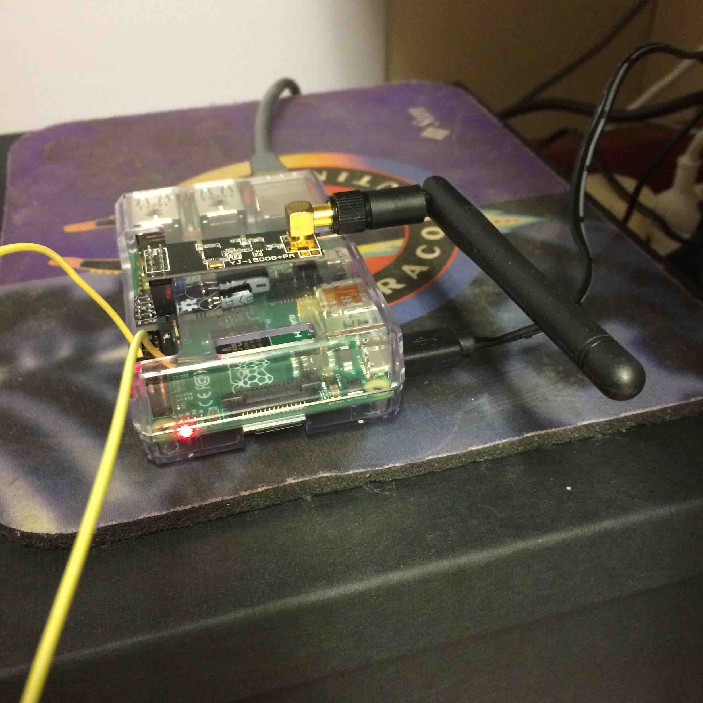
Just to let all know that I'm quite happy with my current setup: Domoticz as controller and a gateway running on a Raspberry Pi 2.
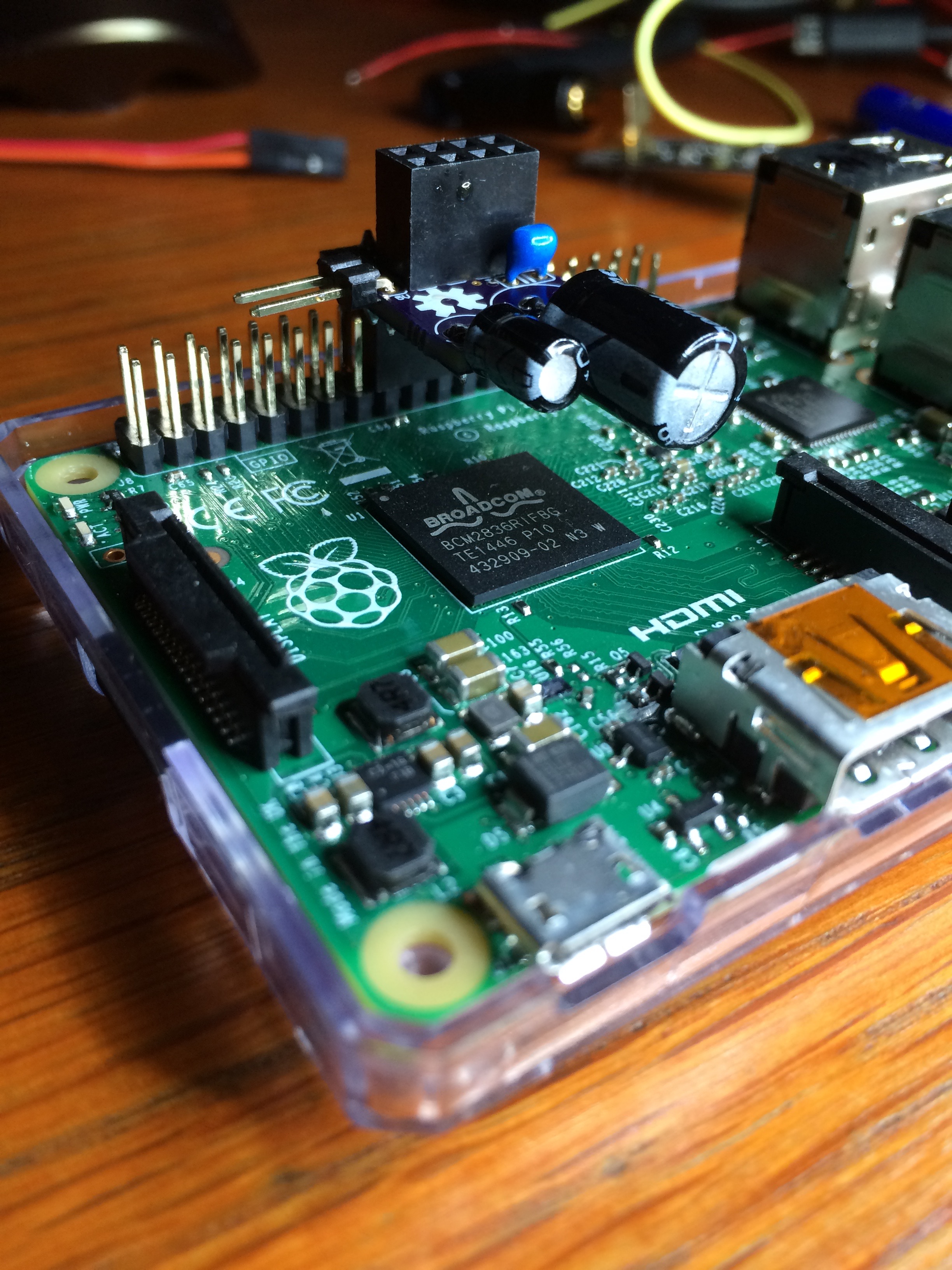
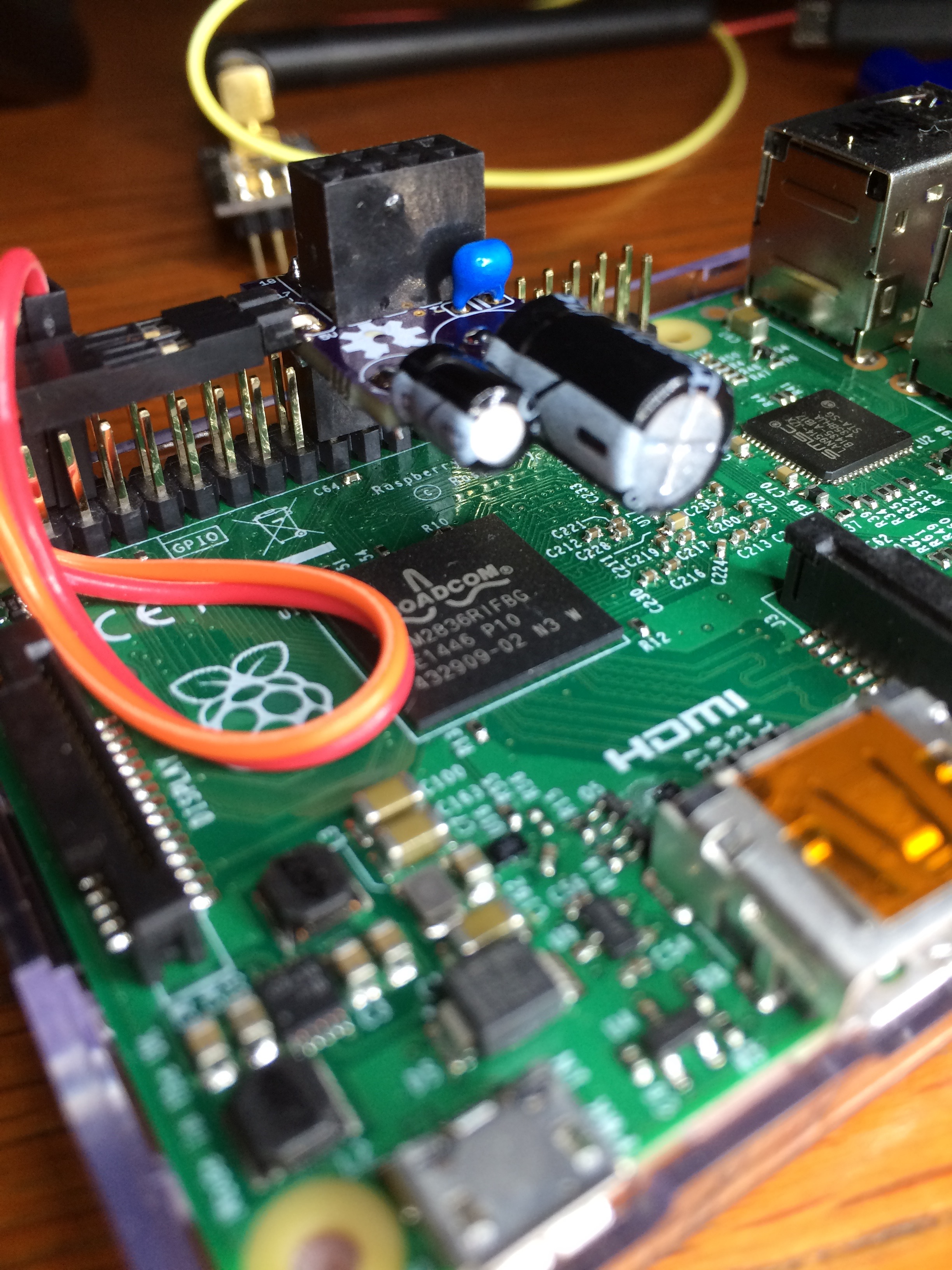
The serial gateway I use is made of a small board sitting on the GPIO pins of the same Raspberry.
The PCB for this gateway is public (https://oshpark.com/shared_projects/aXLXBO3f), the code to run is available from the Mysensors raspberry implementation. This creates a serial port which then needs to be represented via a symbolic link with a short name, so that Domoticz can see it.This allowed me to eliminate a physical gateway, since the raspberry runs as a gateway and a controller at the same time.
Many thank to the MySensors team for the sensor software (same shoutout to the Domoticz designers) :-)
-
Just to let all know that I'm quite happy with my current setup: Domoticz as controller and a gateway running on a Raspberry Pi 2.
The serial gateway I use is made of a small board sitting on the GPIO pins of the same Raspberry.
The PCB for this gateway is public (https://oshpark.com/shared_projects/aXLXBO3f), the code to run is available from the Mysensors raspberry implementation. This creates a serial port which then needs to be represented via a symbolic link with a short name, so that Domoticz can see it.This allowed me to eliminate a physical gateway, since the raspberry runs as a gateway and a controller at the same time.
Many thank to the MySensors team for the sensor software (same shoutout to the Domoticz designers) :-)
-
I was a teenager when the first Macintosh came out, being impressed it was faster then the LISA I had seen the year before. So yeah :-), I still have some old-school stuff laying around.
Going back to electronics and building stuff is super fun, made me remember why I wanted to be an electronics engineer in the first place. One tends to forget that after managerial jobs for many years. This site has given me inspiration for little projects I did not know I needed to do :-).
In any case, the tools to design and build, the option to realise those designs cheaply (e.g. OSHPark) are simple lightyears beyond what I had available in the eighties.
-
And for those interested: my design for a low power node is also available on OSHpark:
https://oshpark.com/shared_projects/qnkNIMZx
and it's companion (1 of many to come)
https://oshpark.com/shared_projects/IOHUNYT2 -
@GertSanders This looks really good, and will greatly simplify my set-up. I'm going to order the board from OSH Park - is there a list of components / instructions (I notice the board has solder jumpers)?
-
@MikeF:
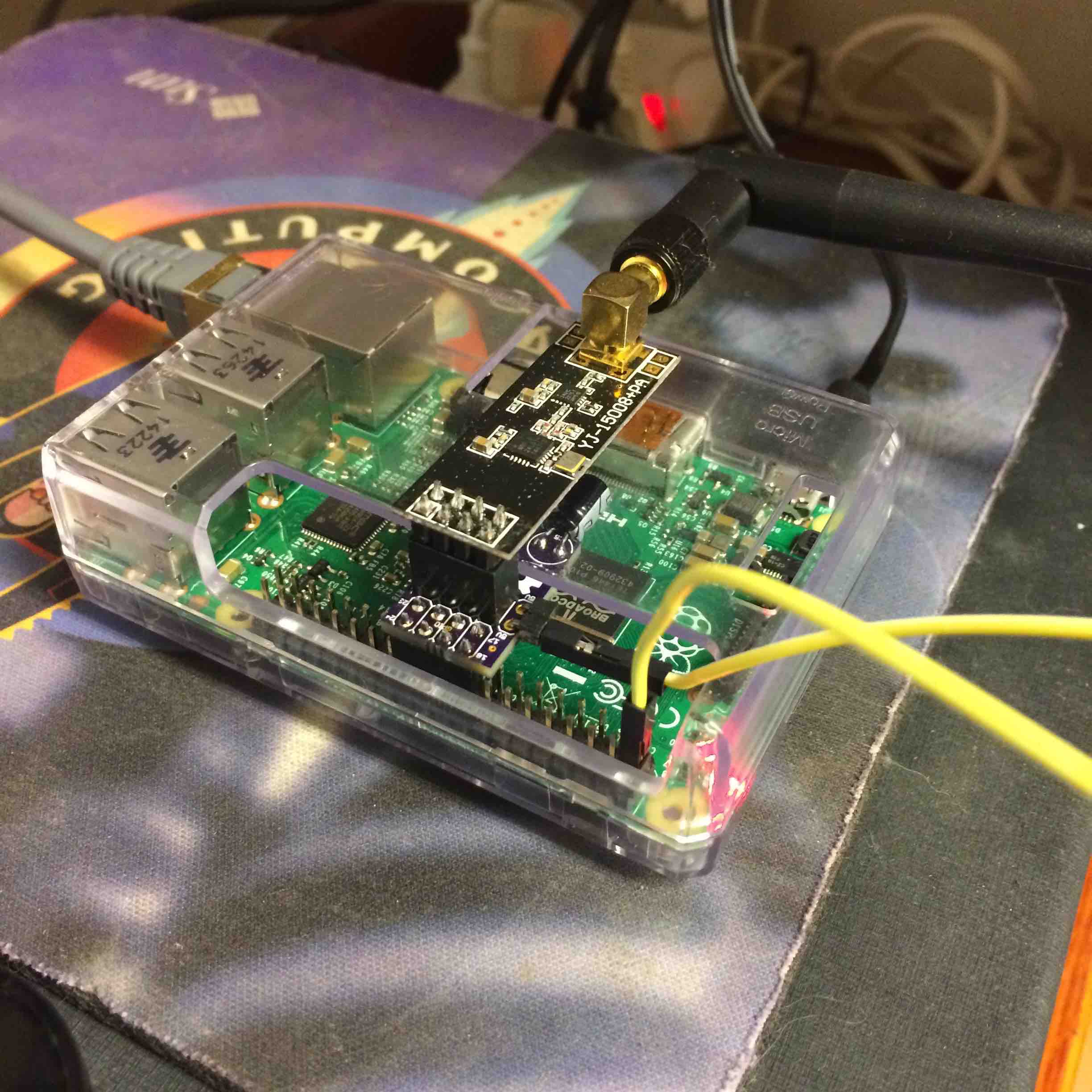
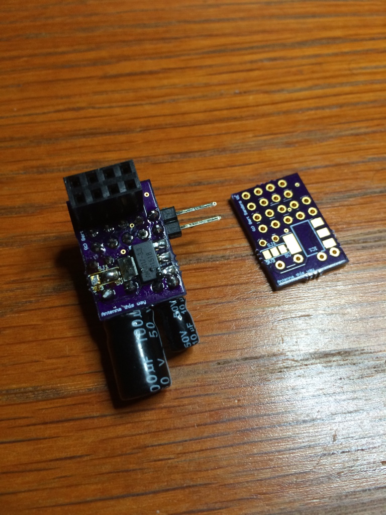
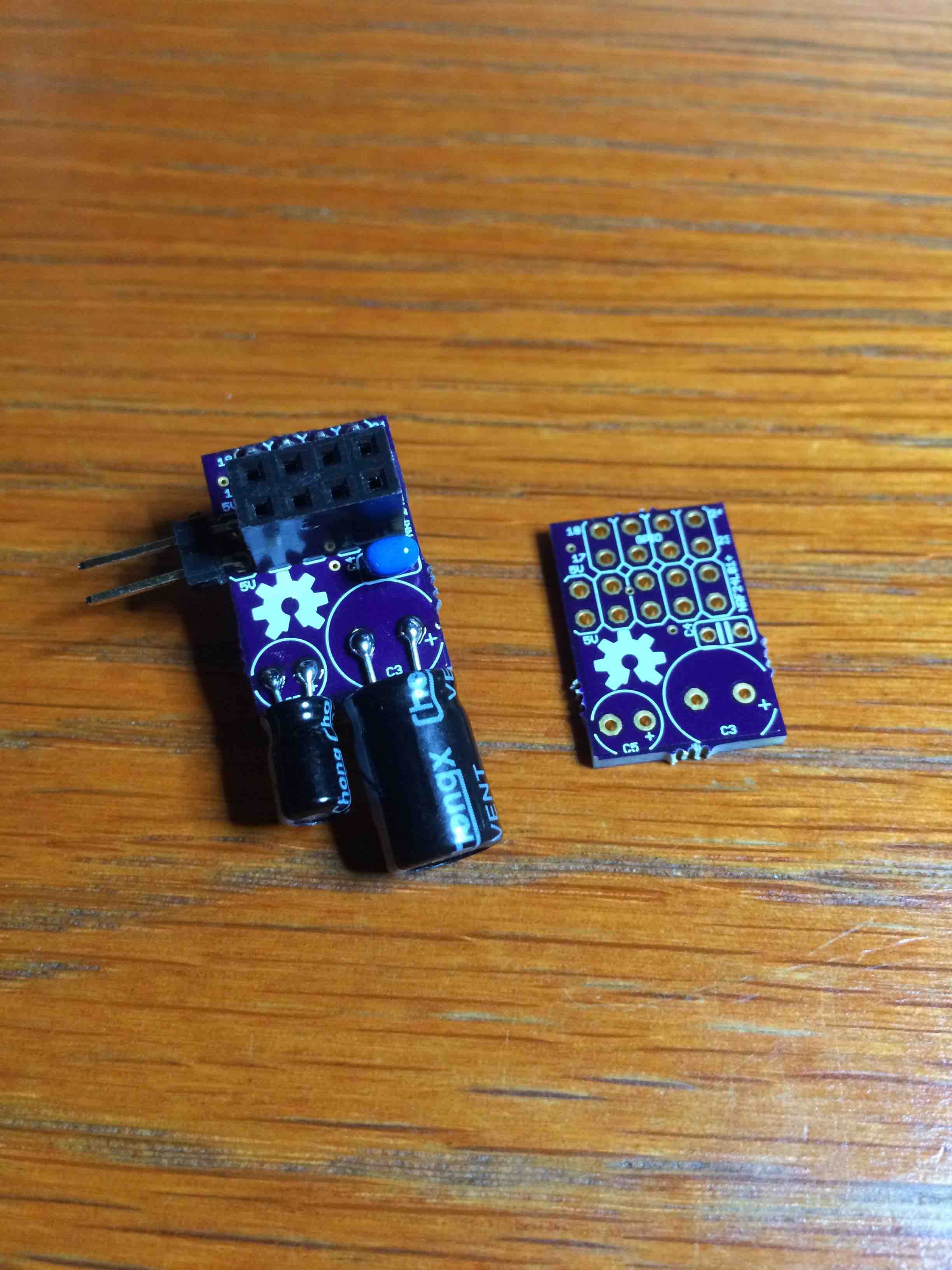
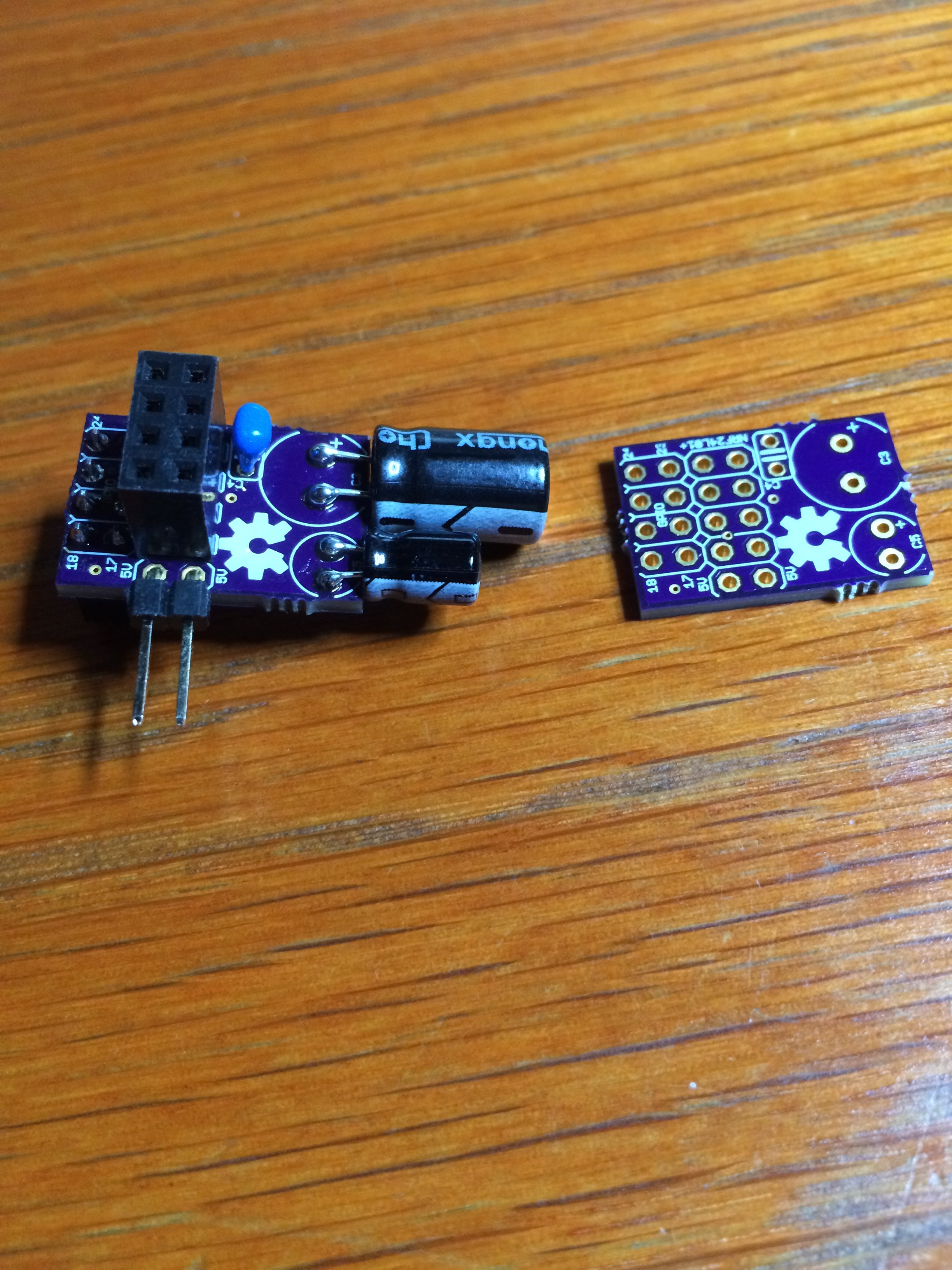
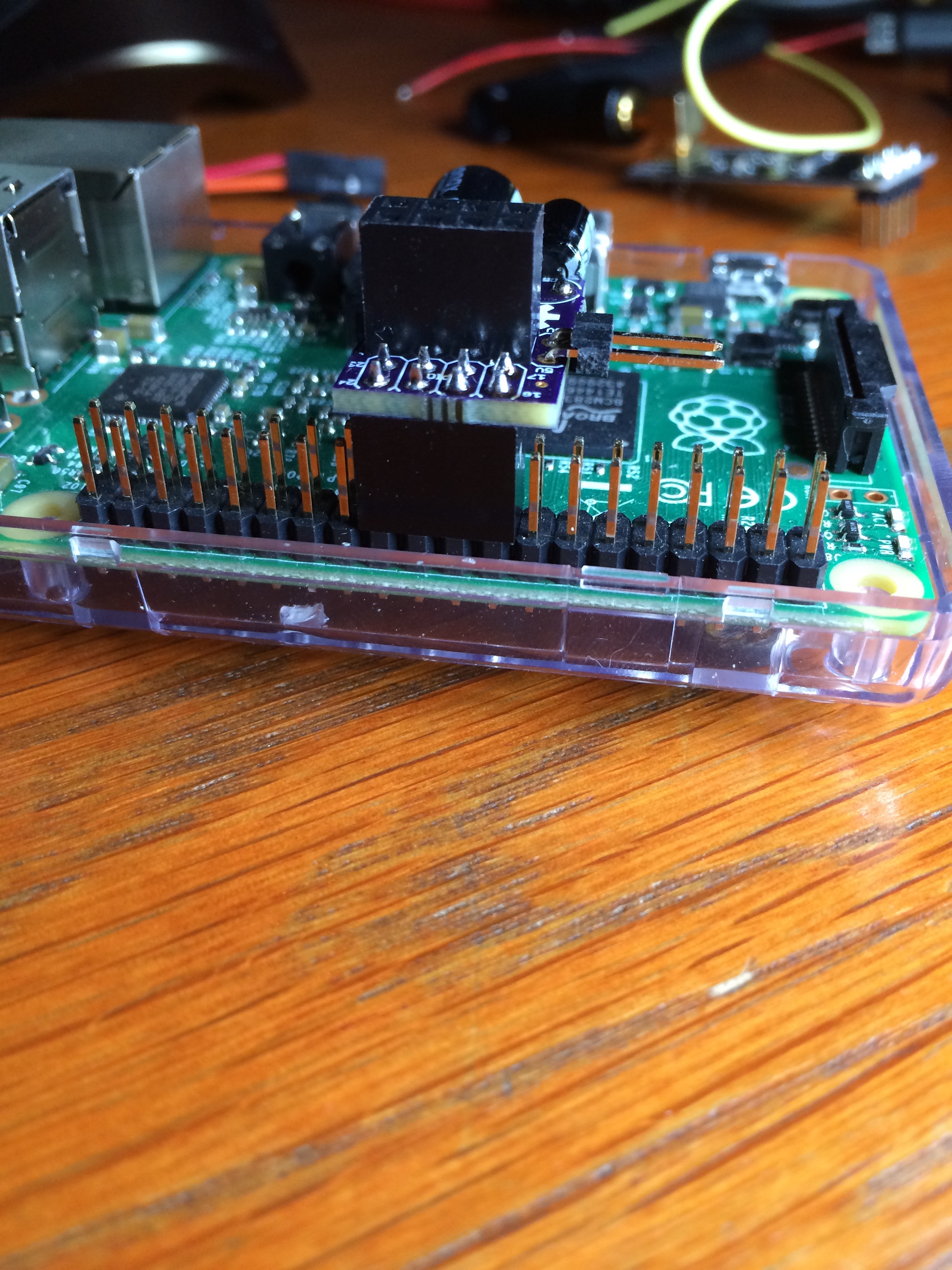
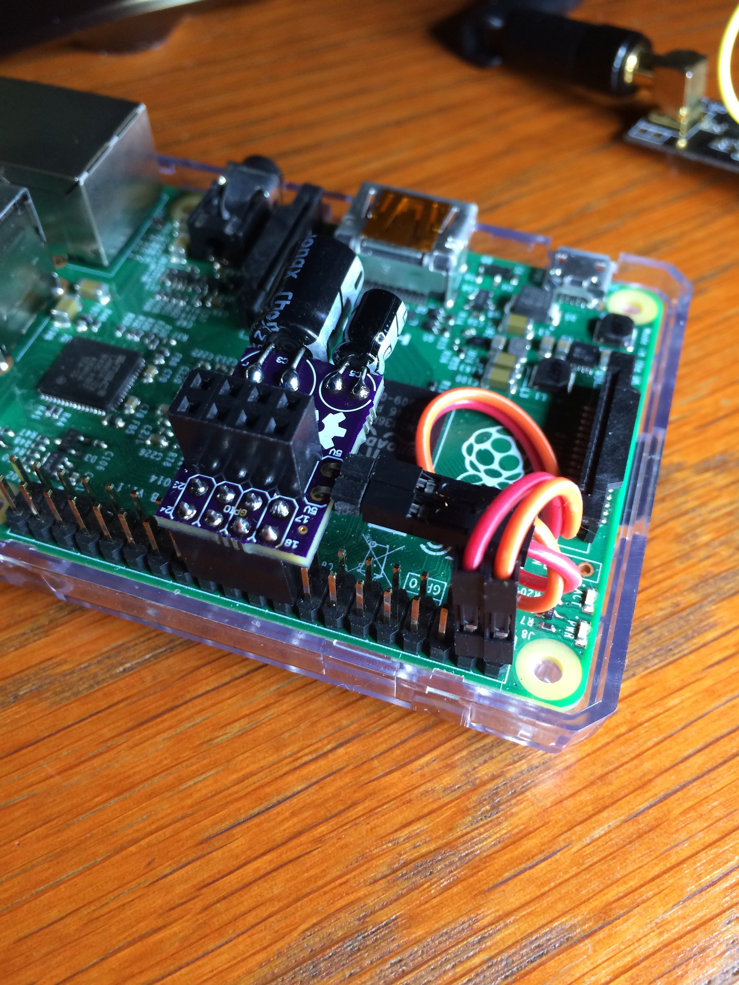
There is 1 jumper to solder, and you need it to choose the power input towards the NRF24. If you bridge the middle with the 5V side, you need to connect 5V from the GPIO pins 2 or 4 (or both if you want) to one of the 5V pins on the small PCB using a wire (as you see in the images). This will feed the onboard powerregulator with 5V so that this one can give 3V3 to the radio.If you bridge middle with 3V3 side, then power is taken directly from the 3V3 pin on the GPIO and connected straight to the radio Vcc pin.
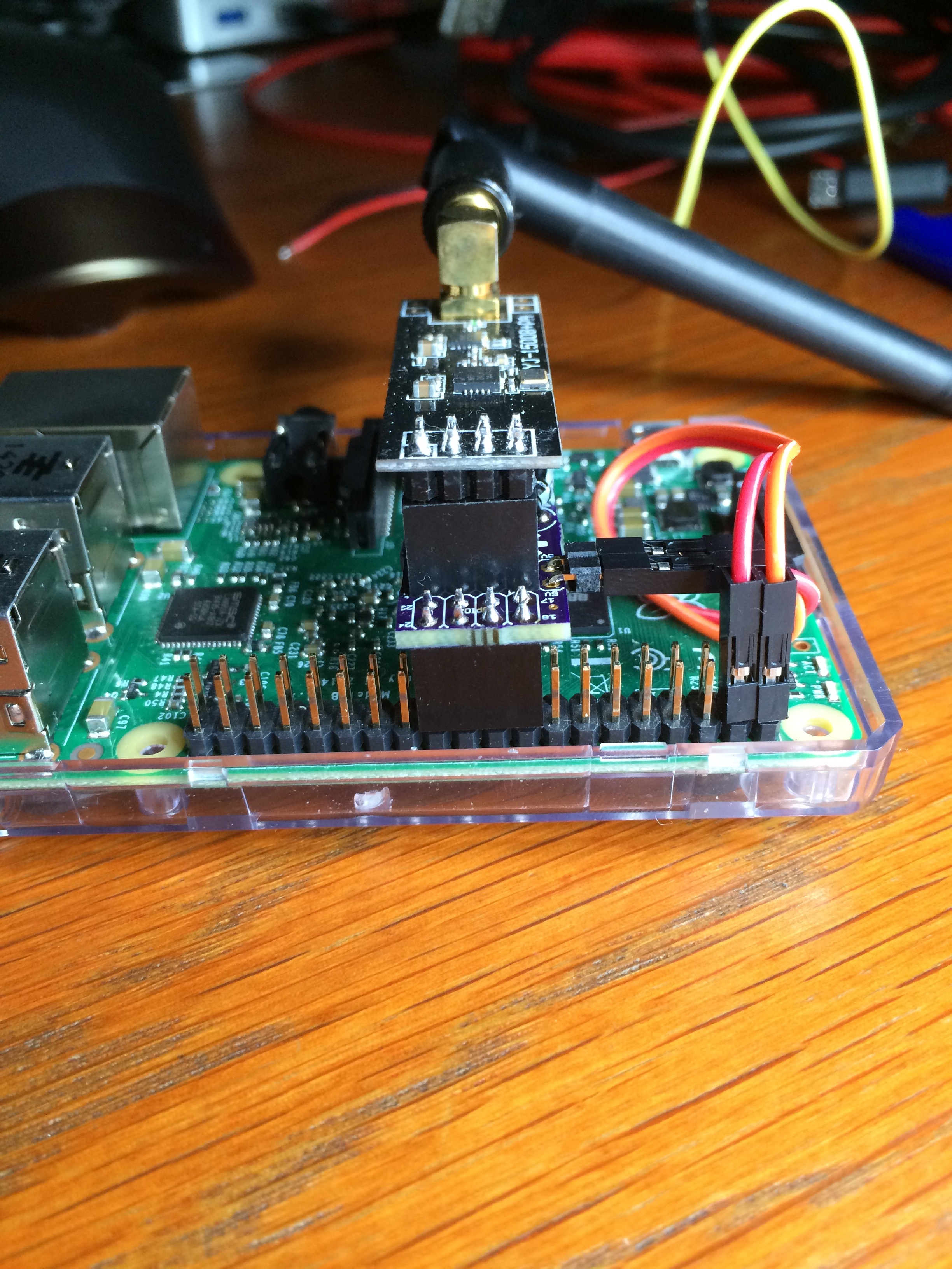
For the radio with external SMA antenna, you need to use the 5V from the Raspberry (actually directly from the USB source). The smaller NRF24's (without external antenna) do not need more power and the GPIO 3V3 pin (and Raspberry's 3V3 regulator) can deliver sufficient power.
I chose to use a small wire to connect the 5V, so that the cost of the board was low. OSHPark is nice for small series and cheap in the smaller sizes (certainly given the quality of PCB they deliver). Very sad that 5V is only presented on the edge of the GPIO. It would have been nicer to have at least one 5V pin with shorter distance from the SPI pins. I use my setup with the more powerful nrf24L01+ with SMA antenna, hence the "5V hack", but if one uses the smaller radios with antenna on the board, then no wire is needed since 3V3 is available within the connector.
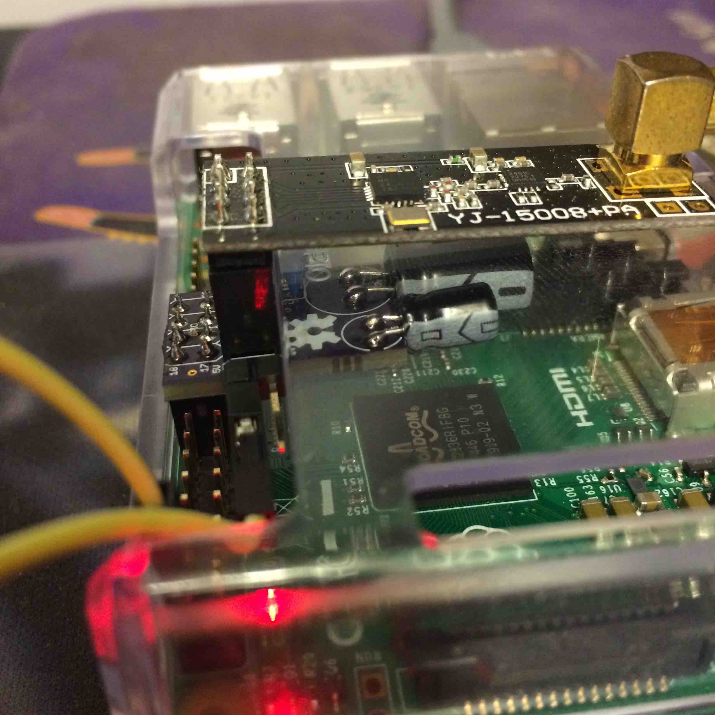
The onboard power-regulator is a LM1117 at 3V3 fixed. I will add a few more pictures tonight.
Capacitors are 100nF, 10uF and 100uF respectively (ranging from small to large). The two larger capacitors are polarised electrolytic, the small one is a ceramic type.
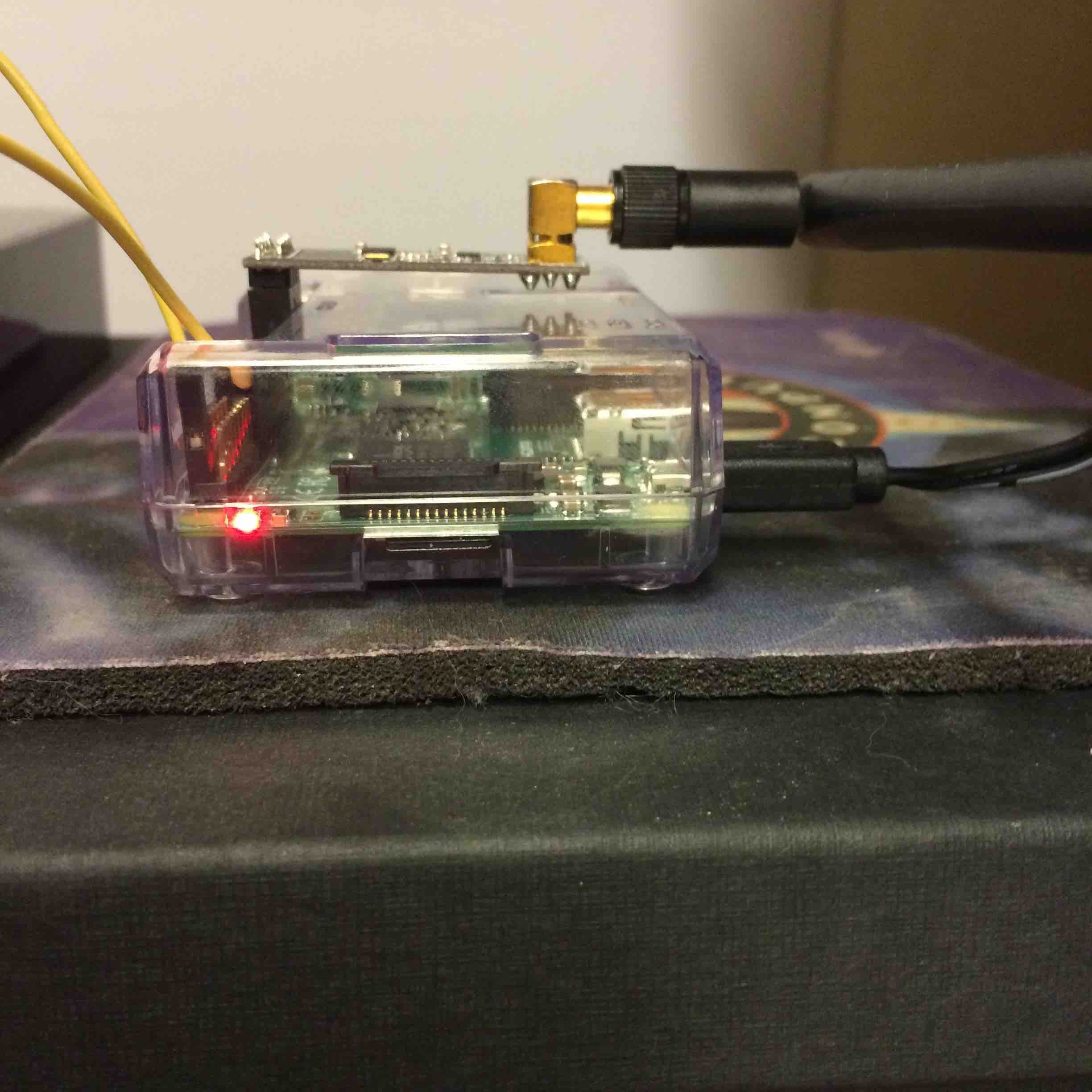
Normally the electrolytic capacitors are to be mounted verticaly. In my case I soldered them sideways, so it would all fit within the raspberry case. But even vertically they stay under the radio board. The largest one may touch the bottom, so insulation needs to be put on top of the capacitor in that case I think, I will check.
-
This is interesting stuff! Do you know if the raspberrypi port supports rf69 as well?
-
@Anticimex: no idea. I have not used the RF69 so far. Still a lot to learn from the "classic" nrf24l01+ :-).
But if the same pins are used in the same location, then I believe it depends on the software. The SerialGateway software for Raspberry. Maybe one of the original designers of that gateway can tell you if they support RF69. Would be nice !
-
Here is an image of the voltage regulator I use:
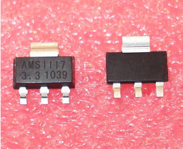
SOT223 package, more then powerful enough for a single SMA-type NRF24.
-
@GertSanders Thanks for the extra info - that was very helpful.
-
some more images
-
Hi @GertSanders, I've received the PCB, built the adaptor and the software as per the MySensors Raspberry Port GitHub. I've created a symlink to /dev/ttyMySensorsGateway (/dev/ttyUSB40), which Domoticz, and I see the following in the Domoticz log:
2015-09-29 17:48:40.503 MySensors: Using serial port: /dev/ttyUSB40
2015-09-29 17:48:40.503 MySensors: Gateway Ready...However, I can't see any of the devices on my node - any ideas?
-
In my case I had to restart the nodes, because they did not get the ID from Domoticz. But it takes a few minutes. The gateway is polled every 30 seconds or so. Apart from that, I do not know what could be the problem. Did you allow discovery/addition of new sensors in Domoticz ?
The board should sit between pin 17/18 and 23/24 of the GPIO. There is not much on the board that could malfunction, except maybe the power regulator. Does it give 3V3 ?
Did you solder the jumper right?
If you solder close to the regulator, the board expects connection to 5V (as in my pictures). If you connected the 3V3 side, then it takes power directly from the GPIO. With the large NRF24 that could be insufficient.If all fails, then test without the board: connect the radio directly to the GPIO. That is all I can think of without seeing your setup.
-
Thanks, Gert. I've checked all my soldering (continuity from header to header), the jumper is soldered for 5V, and I'm getting 3V3 across the supply pins of the radio. Board is sitting between 17/18 & 23/24.
I'm still only getting the above 2 lines in the log, i.e., no devices.
I'll try connecting the radio direct to the GPIO later today. -
Cracked it! I'm using an RPi 2, and cat /proc/cpuinfo gives a01041 as hardware version. According to GitHub readme, CE needs to go to pin 15, not 22.
Now working with radio connected directly, but will now need to connect a jumper wire from the adaptor board.
-
Strange, I'm also working on the RPi 2. I will check what I have in my RF24 library, because I'm sure that you can change pin assignment in software instead of needing to resort to extra jumper wire.
When home I will check this tonight. I really need to write out a procedure for this, or we will forget in the future how it should be set up. -
Hello @GertSanders, for the time being I've got the gateway working with CE connected to pin 15, having carried out some 'surgery' to the board!
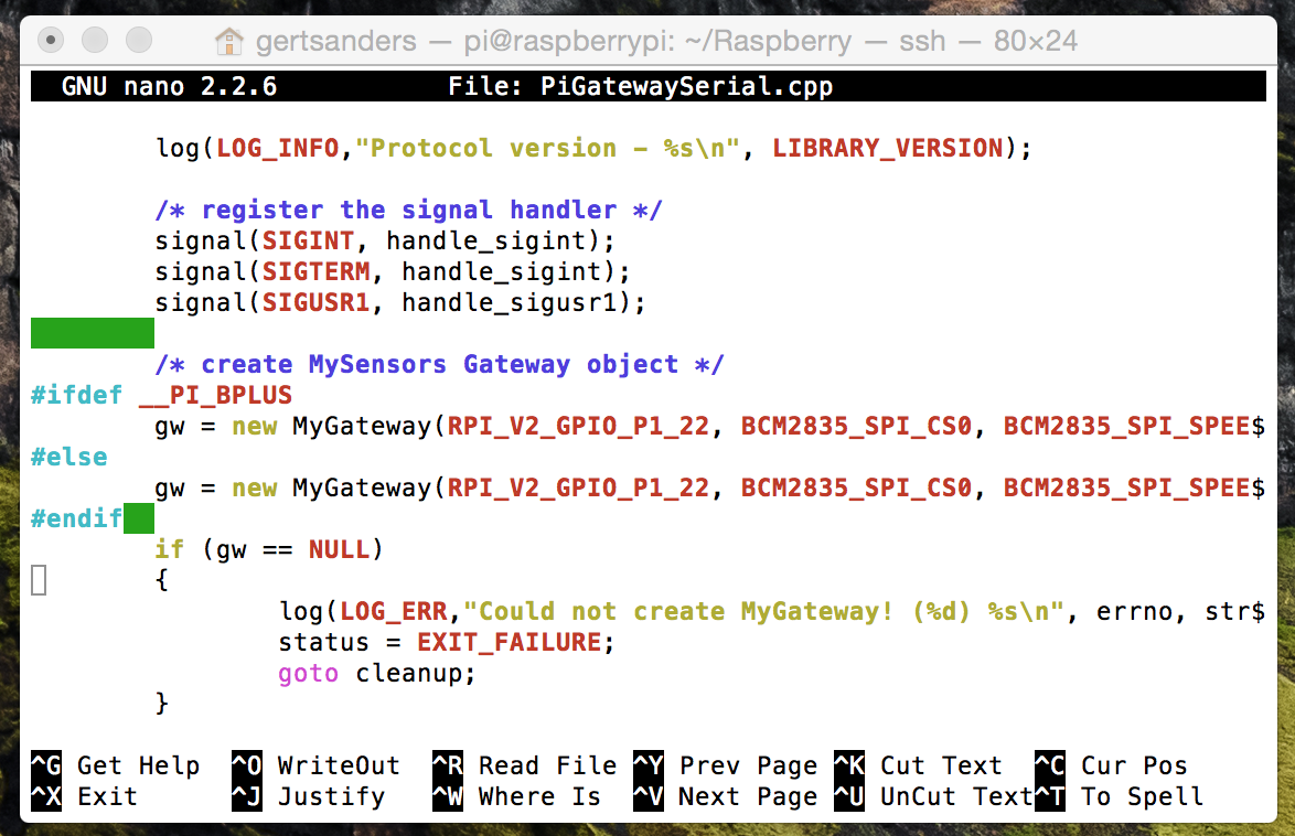
I've found this code in PiGatewaySerial.cpp (line 198 onwards):
/* create MySensors Gateway object */
#ifdef __PI_BPLUS
gw = new MyGateway(RPI_BPLUS_GPIO_J8_15, RPI_BPLUS_GPIO_J8_24, BCM2835_SPI_SPEED_8MHZ, 1);
#else
gw = new MyGateway(RPI_V2_GPIO_P1_22, BCM2835_SPI_CS0, BCM2835_SPI_SPEED_8MHZ, 1);
#endifIs this the 'offending' code?
-
Yes, as the rpi2 is not recognised properly the code compiles for rpib+.
I changed the code so that both rpi b+ as rpi2 have the same: use pin 22
-
@MikeF said:
gw = new MyGateway(RPI_V2_GPIO_P1_22, BCM2835_SPI_CS0, BCM2835_SPI_SPEED_8MHZ, 1);
You will need the code as here above, then no need for surgery
-
Had some time to log into my Raspberry 2 today, and indeed I adapted the code I used for the PiGatewaySerial because a RPI2 is not recognised properly.
So here is what I used as source-file:
I'm not sure where the correction should be made so that the RPI2 is recognised properly (instead of being recognised a s a raspi B+)
Hello! It looks like you're interested in this conversation, but you don't have an account yet.
Getting fed up of having to scroll through the same posts each visit? When you register for an account, you'll always come back to exactly where you were before, and choose to be notified of new replies (either via email, or push notification). You'll also be able to save bookmarks and upvote posts to show your appreciation to other community members.
With your input, this post could be even better 💗
Register Login