My Ideal sensor node PCB
-
My thoughts on a standard room sensor:
This PCB board ($1 or so)
Arduino Pro Micro ($2.50)
nRF24L01+ ($1 or so)
passives and regulator
Box ($2-3)Mounted to the front of the box: PIR motion detector, IR decoder (remote control receier), LDR light sensor. ($1.50 total w/shipping)
Mounted to the side: DHT-22. ($3 with shipping)
Other sensors as needed, with room for some expansion.
My idea is that I can send commands from any room with a handheld IR remote, and the central conrol will know what command comes from which room. So the IR detector (which is very cheap) is also standard.
If I get too many false hits on the motion detector, I might add an external pet-resistant motion detector from the alarm industry.
I wasn't aiming for boost, but if it's small and cheap and optional I might change my mind. One option is to use the $5 boost-only board Axilent was proposing, if I only rarely needed boost power. (I don't want to solder any microscopic chips myself tho).
Garage, attic, crawl space, water meter on the irrigation, etc would differ from this typical indoor room sensor, as would a clock module. I imagine some with wall power, some battery powered. Some boxes would be waterproof (really, just reasonably weather resistant).
I would have enough pins left over to drive an LCD display if I wanted one; character or graphic.
And this doesn't count the Christmas light control.
Some prices above assume buying around 10 or so, some do not. 3.3v APM is a bit more.
-
I've just sent my PCB off for manufacturing. My design spec was pretty close to your requirements. It looks like this:
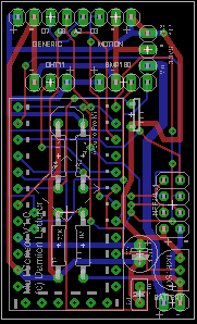
It's 5x3cm. I've panelised it so that I fit 3 across on a 5x10 board. Total cost for 30 boards from itead is $20. It's 5x3 because that's the size of a double AA battery holder. So I'll have two options: either hot-glue it onto the top of the battery holder, or mount it beside a battery holder (making a total footprint of 5x6) which will half the height to fit into most plastic cases.
It supports the 3.3v and 5v pro minis, with access to A5 and A6. It uses the space underneath the APM for the 4 resistors on the board (voltage divider plus others).
It has a socket for the nRF24L01+. It doesn't hang over the edge, it actually hangs over the APM. My spaghetti board prototype showed no problems with this configuration. It makes it much more compact.
It has space for a DHT-11 and a BMP180 for pressure. It has space for the 3.3v step-up converter. It has a DS1820 onboard and also a photoresistor light cell. It then breaks out several pins for motion, soil moisture and distance sensors. The "generic" breakout exposes Vcc, Gnd, D7, D8 and A2.
All in all, it provides support for all my standard configurations, which are:
- All sensors have light, temp and motion on board
- Configuration A: Humidity (DHT-11)
- Configuration B: Humidity (DHT-11) and baro pressure (bmp180)
- Configuration C: Door reed switch
- Configuration D: Distance
- Configuration E: Soil moisture
Based on the conversations recently about the inefficiency of the step-up converter, I'm yet to decide whether I'll make my own step-up converter board that fits in the same slot on my PCB, or whether I'll create v2 that scraps the step-up and uses the XC9140A331 or something else onboard.
@Bandra Exactly what I was going to do. Nice!
Question: Since pin D3 is in great demand (the only available intrupt pin for waking the pro-mini) how did you decide what sensors have access? I think only one sensor can connect to the D3 pin, right? I suppose the door reed switch sensor gets priority, or does distance get the D3 pin?
Right now I'm leaning to the PIR motion sensor getting the D3 pin. I think it's the only way to run a motion sensor off a 'sleeping' pro-mini, right?
Here is what I'm currently thinking...
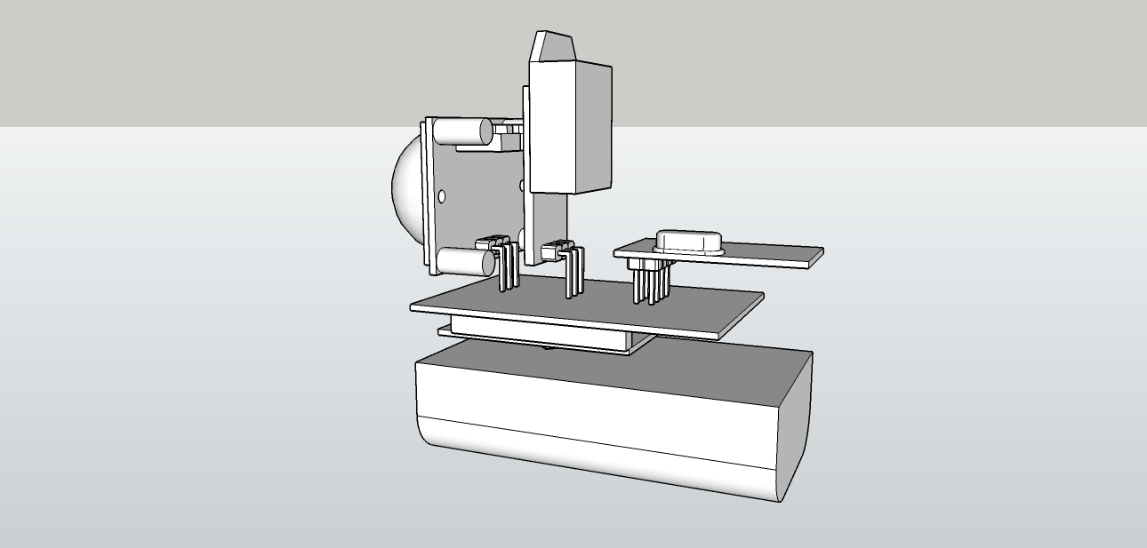
From the bottom...a 2xAA battery pack, the pro-mini under the PCB in question, and a PIR, temp/humidity, and the radio. I'll break-out the other pins for some other things too, but this is the main function. I could replace the temp/humidity with the Dallas.
Thoughts?
-
@therik said:
I would also like to use either the DHT-22 module (it gets dry here in the desert) or the Dallas, also include a PIR sensor, run off 2xAA Eneloops. I like the waterproof box you found.
DHT-xx
I would like the option of using either, as the DHT-22 is better but bigger and more expensive. The DHT-11 is cheap enough to almost always be used unless a DHT-22 is called for. (Substitute AM230x as appropriate here).
The sheets I have show the DHT-11 with 0.1" pin spacing and a 12x5.5mm footprint.
What I see for AM2303 (DHT-22ish) is 2mm spacing and 15.1x7.7mm footprint.I see two cases: solder the sensor directly on the PCB when the pcb has good air circulation, or use wires to an external unit if the box is sealed or closed off (not enough air flow). No PCB footprint is needed for the latter (off PCB mounting). I estimate that I am somewhat more likely to use a DHT-22 off PCB and a DHT-11 on PCB.
In the solder-to-PCB case, the DHT-11 could be soldered to the 0.1" hole grid of the prototyping area I mentioned, but the DHT-22 would need custom holes for 2mm spacing as well as a larger footprint. Since I'm more likely to use a DHT-22 where accuracy matters more to me (and because it's larger) I'm more likely to mount it off PCB anyway so I don't need a special place for it on the PCB. I might loosely "reserve" a place in the prototyping area for the DHT-11, with a (cuttable) trace from a digital pin to the DHT-11's data pin. But if I don't need an onboard DHT-11 (because I have an off-board DHT-xx or just don't care to measure humidity) I could use those holes for other functions.
PIR
So far my thought has been to mount a PIR externally (eg: on the outside of a box, not on the PCB), so all I need on the PCB is holes for wiring power/ground/data. I haven't been coming up with a use case for mounting the PIR on the PCB directly.
When I say "wiring up an external sensor" I have two things in mind. One is to solder header pins on the PCB and use Dupont connector jumpers to go to a sensor or actuator (quick and flexible), the other is to solder wires directly (more compact and reliable in the long run). With a 0.1" prototyping grid, I can do either.
@Zeph I have a DHT-22 and my pin spacing is 0.1".
I was thinking of connecting the PIR and DHT-22 directly to the PCB and building a case around it. Of course, I could also use wires to remote the DHT-22 or PIR, but I like the option of direct connecting.
Oh yea, and where are you getting the DHT22 for $3? I need to use these due to the low humidity here in the desert. The DHT11 only goes to 20% and we a lower than that much of the year.
-
@Bandra said:
I've just sent my PCB off for manufacturing. My design spec was pretty close to your requirements.
I like your design.
One newbie question I have (never having done my own boards yet) is about how hard it is to cut apart the PCBs when you panelize them to subunits smaller than the PCB manufacturer separates for you. Do you use shears of some sort, or a band saw, or a dremal saw or what? Seems like you'd need to be very precise to not damage adjacent traces.
It supports the 3.3v and 5v pro minis, with access to A5 and A6.
I see holes for A4 and A5. Most APM's also provide A6 and A7 (which are analog in only). I use those for things like the VRAW voltage divider, which will never need to be used as a digital pin.
One pattern is to place A4+A5 and A6+A7 inside the perimeter pins and offset half a pin, see for example: http://www.ebay.com/itm/191117208428
Another pattern is to add 4 perimeter pins for A4-A7 at the far end from the serial programming pins, see for example: http://www.ebay.com/itm/271512227109
I was thinking it would be possible to accommodate either on the sensor board.
It has a socket for the nRF24L01+. It doesn't hang over the edge, it actually hangs over the APM. My spaghetti board prototype showed no problems with this configuration. It makes it much more compact.
It does make it more compact so I'd prefer it if is works well, but Nordic's recommendation is not to place the antenna over a ground or power plane or too close. Somebody else posted a reference recently. It may depend on how far above the PCB the nRF24L01+ is mounted. Your milage may vary but it is worth testing on the actual PCB. If we can get solid radio signals without hanging at least the antenna outboard, I'm all for it.
-
@Bandra Exactly what I was going to do. Nice!
Question: Since pin D3 is in great demand (the only available intrupt pin for waking the pro-mini) how did you decide what sensors have access? I think only one sensor can connect to the D3 pin, right? I suppose the door reed switch sensor gets priority, or does distance get the D3 pin?
Right now I'm leaning to the PIR motion sensor getting the D3 pin. I think it's the only way to run a motion sensor off a 'sleeping' pro-mini, right?
Here is what I'm currently thinking...
From the bottom...a 2xAA battery pack, the pro-mini under the PCB in question, and a PIR, temp/humidity, and the radio. I'll break-out the other pins for some other things too, but this is the main function. I could replace the temp/humidity with the Dallas.
Thoughts?
@therik
D3 is an interesting one. As you can see on my board, I've broken it out with a +'ve and -'ve and together called the 3 pins "motion". However, it's dead easy just to use D3 and either the positive or neg for the door switch (depending on whether I want a high or low switch (so it supports both normally open and normally closed).The only drawback is, of course, (as you point out) that I can't run motion and door switch on the one sensor node. But that's ok. I've tried really hard to cram as many sensors onto each node, but the door switch sensors will just have to be dedicated. For the price of each node, I'm ok with that.
I like your layout. I was fearful of making the node too tall, which is why I'll connect my PIR with wires rather than sit it on the board. It should sit inside a plastic case a bit better that way. I'll see if I can take some photos of my prototypes to show you my thoughts.
-
@Bandra said:
I've just sent my PCB off for manufacturing. My design spec was pretty close to your requirements.
I like your design.
One newbie question I have (never having done my own boards yet) is about how hard it is to cut apart the PCBs when you panelize them to subunits smaller than the PCB manufacturer separates for you. Do you use shears of some sort, or a band saw, or a dremal saw or what? Seems like you'd need to be very precise to not damage adjacent traces.
It supports the 3.3v and 5v pro minis, with access to A5 and A6.
I see holes for A4 and A5. Most APM's also provide A6 and A7 (which are analog in only). I use those for things like the VRAW voltage divider, which will never need to be used as a digital pin.
One pattern is to place A4+A5 and A6+A7 inside the perimeter pins and offset half a pin, see for example: http://www.ebay.com/itm/191117208428
Another pattern is to add 4 perimeter pins for A4-A7 at the far end from the serial programming pins, see for example: http://www.ebay.com/itm/271512227109
I was thinking it would be possible to accommodate either on the sensor board.
It has a socket for the nRF24L01+. It doesn't hang over the edge, it actually hangs over the APM. My spaghetti board prototype showed no problems with this configuration. It makes it much more compact.
It does make it more compact so I'd prefer it if is works well, but Nordic's recommendation is not to place the antenna over a ground or power plane or too close. Somebody else posted a reference recently. It may depend on how far above the PCB the nRF24L01+ is mounted. Your milage may vary but it is worth testing on the actual PCB. If we can get solid radio signals without hanging at least the antenna outboard, I'm all for it.
@Zeph
For cutting the boards I'll be using a really sharp Stanley knife. I live in an apartment with my young family, so containing the dust is a big consideration for me. A Stanley knife is about the "cleanest" way to cut them. It just takes a little more elbow grease.I've left about 3mm between each board (since I have 3 x 3cm boards to fit across 10cm). Plenty of room to cut between :)
Yeah, I know that Nordic recommend not to run the antenna over a plane. I plan to solder a 2x4 header onto my PCB and slot the nRF into that. My prototype had pretty decent range when I tried it. I'll see how it works when my PCBs come in. I may need a rev 2 yet :)
-
@Zeph I have a DHT-22 and my pin spacing is 0.1".
I was thinking of connecting the PIR and DHT-22 directly to the PCB and building a case around it. Of course, I could also use wires to remote the DHT-22 or PIR, but I like the option of direct connecting.
Oh yea, and where are you getting the DHT22 for $3? I need to use these due to the low humidity here in the desert. The DHT11 only goes to 20% and we a lower than that much of the year.
@therik said:
@Zeph I have a DHT-22 and my pin spacing is 0.1".
Cool.
Oh yea, and where are you getting the DHT22 for $3?
I understand the desire to go below 20% RH.
I am using AM2302. Many of the sources for "DHT22" are actually substituting the AM2302 (including the current MySensors store link). Do you have a datasheet for the real DHT-22?
And I goofed, $3 was based on winning a bid for my first one, they start at $4 w free shipping on eBay for "Buy it Now", tho they can be had for closer to $3 in lots of 5 on AliExpress.
I got mine before coming to this site; I would now tend to suggest following the links in the MySensors store if you are getting it from eBay - who knows how good the "cheapest offering" on eBay or AliExpress is?
-
@Zeph
For cutting the boards I'll be using a really sharp Stanley knife. I live in an apartment with my young family, so containing the dust is a big consideration for me. A Stanley knife is about the "cleanest" way to cut them. It just takes a little more elbow grease.I've left about 3mm between each board (since I have 3 x 3cm boards to fit across 10cm). Plenty of room to cut between :)
Yeah, I know that Nordic recommend not to run the antenna over a plane. I plan to solder a 2x4 header onto my PCB and slot the nRF into that. My prototype had pretty decent range when I tried it. I'll see how it works when my PCBs come in. I may need a rev 2 yet :)
@Bandra said:
For cutting the boards I'll be using a really sharp Stanley knife.
Meaning a box cutter knife? So you probably use a straight edge and score the board with the knife (both sides?) Then just break it on the line? That sounds pretty feasible, other than:
I've left about 3mm between each board (since I have 3 x 3cm boards to fit across 10cm). Plenty of room to cut between :)
Ever since SMT, people have new definitions of "plenty of room" :-)
-
My overall thinking is that the breadboard area will allow reasonably simple addition of many types of sensors or actuators, so I am suggesting minimizing the dedicated circuitry and maximizing the breadboard area. However it makes sense to have dedicated space on the PCB for sensors and devices which are likely to be commonly used and especially if they do not fit the 0.1" hole grid. For example, a surface mount LDO regulator for the radio.
There's another candidate which meets this criterion for me, and I've edited it into the Origional Post - onboard external serial Flash. This could be as easy as a SOIC-8 outline (and traces) for the AT24C series, or other serial Flash memory. Optional of course.
-
Gentlemen,
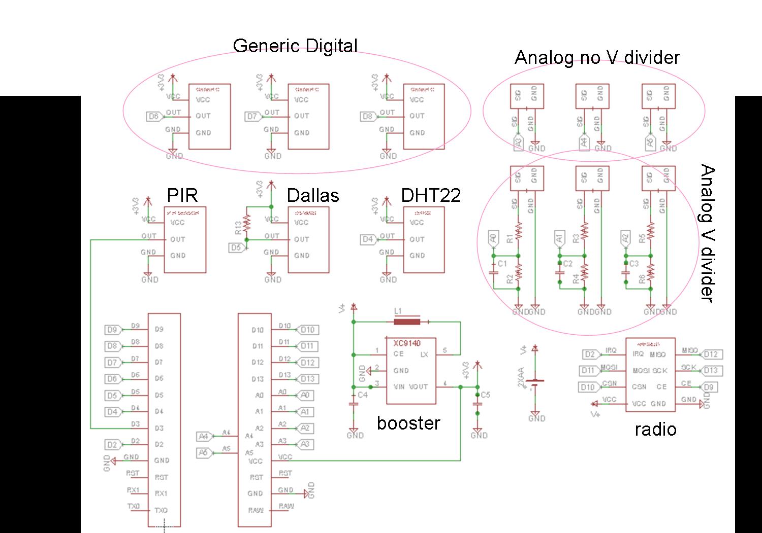
For anyone who is interested I have attached a schematic of my proposed "shield". Have a look if you so choose, and if you notice something wrong or incorrect, please let me know. One thing I'm not sure is...does the DHT22 temperature/humidity sensor need an external pull-up resistor?
-
Gentlemen,
For anyone who is interested I have attached a schematic of my proposed "shield". Have a look if you so choose, and if you notice something wrong or incorrect, please let me know. One thing I'm not sure is...does the DHT22 temperature/humidity sensor need an external pull-up resistor?
@therik said:
Very nice. No "mistakes", just some questions.
For anyone who is interested I have attached a schematic of my proposed "shield". Have a look if you so choose, and if you notice something wrong or incorrect, please let me know.
This is a base board for the Arduino Pro Mini, right? Are you making use of A6 and A7?
Why three voltage dividers of this style? Do you anticipate having multiple higher voltages to measure? I would tend to use one for VRAW. I guess you could populate one half with a resistor and jumper the other, then tie something like an LDR between the analog input and VCC or Ground.
I'm a little unusual, as I want the option to tie the nRF's IRQ to D8 (input capture 1). This is to allow T1 to be used as a high precision timer and capture the time a packet arrives, and I can also use that capture to generate an interrupt based on that - keeping D2 free for INT0.
I am also using an interrupt driven DHTxx lib, which uses Int0 or Int1 (pin 2 or 3) rather than pin 5.
Are the PIR and Dallas (one wire) and DHT22 dedicated footprints on the board, or connectors?
-
Indeed, a pro-mini clone. I thought that A6 and A7 might be too much to squeeze in. I'm thinking of a 3x5 cm board.
Yea, for the voltage dividers, one for measuring the battery level. And two for something else, possibly an IR-based reflective optical sensor. And anything that has a higher output voltage.
Hmm...haven't heard of using nRF's IRQ to D8, can you still wake a sleeping node with this configuration? I guess I just don't have a full grasp on the concept. I just a beginner, so the more I learn the more dangerous I get!
Right, the main sensor on this board is the PIR; which is why I want an interrupt pin to that sensor. However I'd like to also use the magnetic-based sensors also as the main sensor and interrupt.
The PIR, Dallas, DHT22 are separate from the other 'future-proof' region, this should become clear once the layout is complete.
Anyone have a solid answer on whether the DHT22 needs an external pull-up resistor?
@therik said:
Indeed, a pro-mini clone. I thought that A6 and A7 might be too much to squeeze in. I'm thinking of a 3x5 cm board.
OK. I like to use one of them for a dedicated measurement of VRAW, since it cannot be used as an additional digital I/O like A0..A5
Yea, for the voltage dividers, one for measuring the battery level. And two for something else, possibly an IR-based reflective optical sensor. And anything that has a higher output voltage.
What IR based sensor are you considering that returns analog above VCC? Are you thinking of having 5V power supply and sensors with 3.3v APM?
Hmm...haven't heard of using nRF's IRQ to D8, can you still wake a sleeping node with this configuration?
I believe the answer is "yes, but not in the lowest possible power-down mode".
Case 1: The nRF is power up and may generate an interrupt. In that case you are using a significant amount of power; you can save battery by nevertheless mostly powering down at ATMega, but keeping timer 1 active so D8 can generate a Input Capture 1 interrupt won't be a big deal.
Case 2: You want really minimal power - so the nRF is powered down and isn't generating interrrupts. In that case you don't need D2 or D8, and you can go to the lowest power level (including powering off timer 1); the watchdog may be all you leave running (or some other super low power external device).
At least that's my understanding. I'm still learning too.Anyone have a solid answer on whether the DHT22 needs an external pull-up resistor?
I do not use any pull up resister and I've never seen a circuit which used it.
-
My overall thinking is that the breadboard area will allow reasonably simple addition of many types of sensors or actuators, so I am suggesting minimizing the dedicated circuitry and maximizing the breadboard area. However it makes sense to have dedicated space on the PCB for sensors and devices which are likely to be commonly used and especially if they do not fit the 0.1" hole grid. For example, a surface mount LDO regulator for the radio.
There's another candidate which meets this criterion for me, and I've edited it into the Origional Post - onboard external serial Flash. This could be as easy as a SOIC-8 outline (and traces) for the AT24C series, or other serial Flash memory. Optional of course.
@Zeph said:
There's another candidate which meets this criterion for me, and I've edited it into the Origional Post - onboard external serial Flash.
Have a look at this little fella: http://www.digikey.com/product-search/en?mpart=W25X40CLSNIG&vendor=256
Isn't anybody willing to create a SOIC-8 home for this cute little chip (with SPI traces of course to keep it happy)?
512 KBytes of happiness for logging and OTA programming. Unique ID.
Or you can get twice that memory for 2 cents more.(The above is the chip used by the Moteino. The Anarduino uses a heftier 16 MByte chip: http://www.mouser.com/ProductDetail/Spansion/S25FL127SABMFI101/?qs=sGAEpiMZZMtI%252bQ06EiAoG5SEO4xJJ6RlEmMSz7h3HuQ%3D but that too is possible with the same SOIC-8 footprint, I think)
(The Moteino and Anarduino use different and incompatible radios compared to MySensors, but nevertheless contain possible inspirations for our corner of this exciting little world).
-
Just for completeness, my PCBs came in and I've had a chance to solder them up. The PCBs are really nice. iTead have done a great job. @Zeph, turns out that I didn't need to cut my PCBs because the friendly folk at iTead cut them for me.
Here's a photo of a few things soldered on:
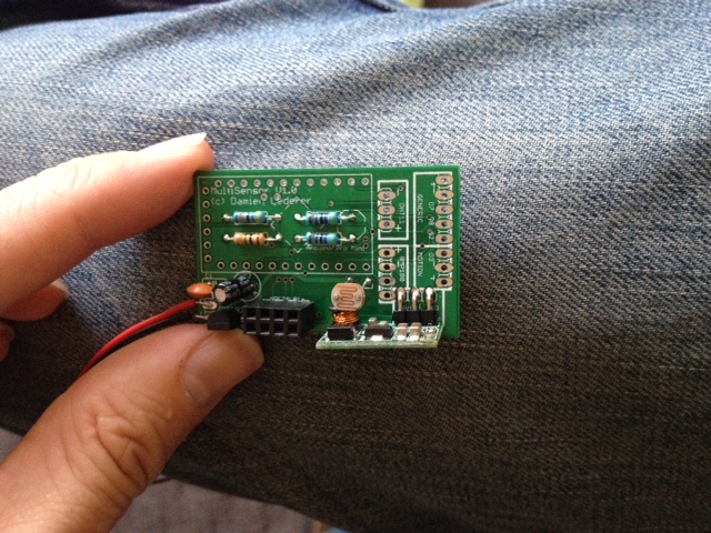
Underneath the APM I have a 1M and 470K resistors for the battery voltage check. There's also a 4.7K resistor for the Dallas DS18B20 temp sensor. Finally there's a 4.7K resistor for the LDR divider circuit.
You can also see the 4x2 header for the radio, the LDR itself, and the 3.3v step-up converter.
Here's the (almost) finished package:
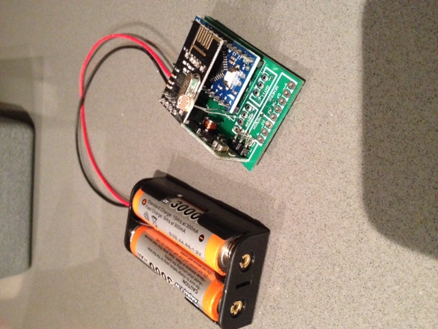
You can see all the exposed solder pads for my various sensor configurations (motion, humidity, baro pressure, door reed switch, distance and soil moisture).
The range on the nRF24 is fine. I put my gateway at one end of the apartment and it easily picked up my sensor at the other end of the apartment (about 10m away through two thick internal walls). So I'm not worried about the nRF24 being parallel to the GND plane.
I actually took off the 4.7uF cap. It's probably my PCB (don't think the auto-route did a great job of it) but it made the radio flaky. Works just fine without it.
Now to find a box to put it in...
-
Just for completeness, my PCBs came in and I've had a chance to solder them up. The PCBs are really nice. iTead have done a great job. @Zeph, turns out that I didn't need to cut my PCBs because the friendly folk at iTead cut them for me.
Here's a photo of a few things soldered on:
Underneath the APM I have a 1M and 470K resistors for the battery voltage check. There's also a 4.7K resistor for the Dallas DS18B20 temp sensor. Finally there's a 4.7K resistor for the LDR divider circuit.
You can also see the 4x2 header for the radio, the LDR itself, and the 3.3v step-up converter.
Here's the (almost) finished package:
You can see all the exposed solder pads for my various sensor configurations (motion, humidity, baro pressure, door reed switch, distance and soil moisture).
The range on the nRF24 is fine. I put my gateway at one end of the apartment and it easily picked up my sensor at the other end of the apartment (about 10m away through two thick internal walls). So I'm not worried about the nRF24 being parallel to the GND plane.
I actually took off the 4.7uF cap. It's probably my PCB (don't think the auto-route did a great job of it) but it made the radio flaky. Works just fine without it.
Now to find a box to put it in...
-
@Zeph said:
There's another candidate which meets this criterion for me, and I've edited it into the Origional Post - onboard external serial Flash.
Have a look at this little fella: http://www.digikey.com/product-search/en?mpart=W25X40CLSNIG&vendor=256
Isn't anybody willing to create a SOIC-8 home for this cute little chip (with SPI traces of course to keep it happy)?
512 KBytes of happiness for logging and OTA programming. Unique ID.
Or you can get twice that memory for 2 cents more.(The above is the chip used by the Moteino. The Anarduino uses a heftier 16 MByte chip: http://www.mouser.com/ProductDetail/Spansion/S25FL127SABMFI101/?qs=sGAEpiMZZMtI%252bQ06EiAoG5SEO4xJJ6RlEmMSz7h3HuQ%3D but that too is possible with the same SOIC-8 footprint, I think)
(The Moteino and Anarduino use different and incompatible radios compared to MySensors, but nevertheless contain possible inspirations for our corner of this exciting little world).
@Zeph said:
Have a look at this little fella: http://www.digikey.com/product-search/en?mpart=W25X40CLSNIG&vendor=256
Interesting but even when I am willing to stock them up (50 pcs) the shipment costs exceed the price of them :(
-
@Zeph said:
Have a look at this little fella: http://www.digikey.com/product-search/en?mpart=W25X40CLSNIG&vendor=256
Interesting but even when I am willing to stock them up (50 pcs) the shipment costs exceed the price of them :(
@marceltrapman Have you looked at AliExpress? Seems they had a few sellers offering this chip.
-
@marceltrapman Have you looked at AliExpress? Seems they had a few sellers offering this chip.
@bjornhallberg said:
@marceltrapman Have you looked at AliExpress? Seems they had a few sellers offering this chip.
I never considered them. Took the plunge for a little less then 0,19 EU per piece :)
Hello! It looks like you're interested in this conversation, but you don't have an account yet.
Getting fed up of having to scroll through the same posts each visit? When you register for an account, you'll always come back to exactly where you were before, and choose to be notified of new replies (either via email, or push notification). You'll also be able to save bookmarks and upvote posts to show your appreciation to other community members.
With your input, this post could be even better 💗
Register Login