Why MySensors isn't using interrupts for nrf24?


  • Sensor nodes in some situations can lost messages due to blocking call to old version of ds18b20 code, sleep calls, working with slow hardware and so on. Gateways in some situations (esp8266) lost messages due to blocking call to network functions.

    Why MySensors is not using interrupts for nrf24? Why MYS code is constantly polling nrf24 via SPI instead of just waiting for interrupt from nrf24? There are some difficulties with the implementation of interrupt-based model?


  • Could it be that the processing is to long to call it in the interrupt function?
    Did you actually tried to attach an interrupt and call the polling method in the interrupt function?


  • @Oitzu sorry, I'm not very familiar with the internal structure of the MySensors code, so I have not yet tried to change anything and just asking. Developers decided not to use interrupts, apparently, they had some reasons. That's why I'm asking.

    For example, atmega328 contains enough memory to hold ring buffer for 5-10 messages, so I think it possible to just store received packets for slow-processed messages into buffer in interrupt routine and process this buffered data in usual way.

    Seems like RPi+nrf24 gateway code may be rewritten in near future using interrupts?


  • I will made a longer post in few days. But I can confirm if I use Ethernet gateway (IBoard with SoftSPI) I loose lot of packets. Same with ESP. In same config (hard and software, except gateway) with SerialGateway, 0% lost after 24h with sensebender sending every 30s.


  • Mod

    IMHO the topic of interrupt handling and the required buffering of messages should be extended to automatic resending of messages when they are not acknowledged by the gateway. Currently the sender has to actively check if an acknowledge is received or not.
    Buffering of messages and automatic resending when a message gets lost would make the whole MySensors library much more robust and would cause the library to get very close to guaranteed delivery.
    This topic has been on my wishlist for a long time, but adding buffering of messages and making the whole library interrupt-safe is not simple to accomplish.
    Furthermore the ecosystem of a target platform (e.g. ESP8266) can still suppress interrupt handling -- we won't have control over it.


  • @robosensor about the RPi Gateway: Well the issue was indeed driven by the wish to get a better RPi Gateway. But the RPi Gateway needs also an huge library update so i don't know if there will be results in the near future.

    @Yveaux isn't the underlying RF24 already providing automatic ack and retransmitting? Well the ack is hardware side but that shouldn't be a problem.

    @Fabien there might be other issues with your setup. Something that prevents the hardware from receiving.


  • Mod

    @Oitzu said:

    underlying RF24 already providing automatic ack and retransmitting

    Yes, but this is only up to the next node and if it fails the message gets lost.


  • @Oitzu I'm experiencing the same problems as @Fabien with packet loss in esp8266-nrf24 gateway. I'm sure this is not hardware setup problem, this is software problem existing only in some cases.

    http://forum.mysensors.org/topic/1870/esp8266-wifi-gateway-port-for-mysensors/224


  • @robosensor okay. I don't have any experience with the esp8266 port yet.
    @Yveaux: Ah okay, you mean like the mysensors ack flag but with automatic buffering and handling by the library?


  • I'm sure of my setup too.
    First board : NRF+PA+LNA with nano on PCB
    Second board : Same NRF with Iboard in the same place
    Same power supply. Test on 2 different ethernet switchs.
    I doesn't move the sensebender (send every 30s). library 1.6 with softSPI on Iboard.
    Store value with node-red flow in influxdb database on ODROID C1
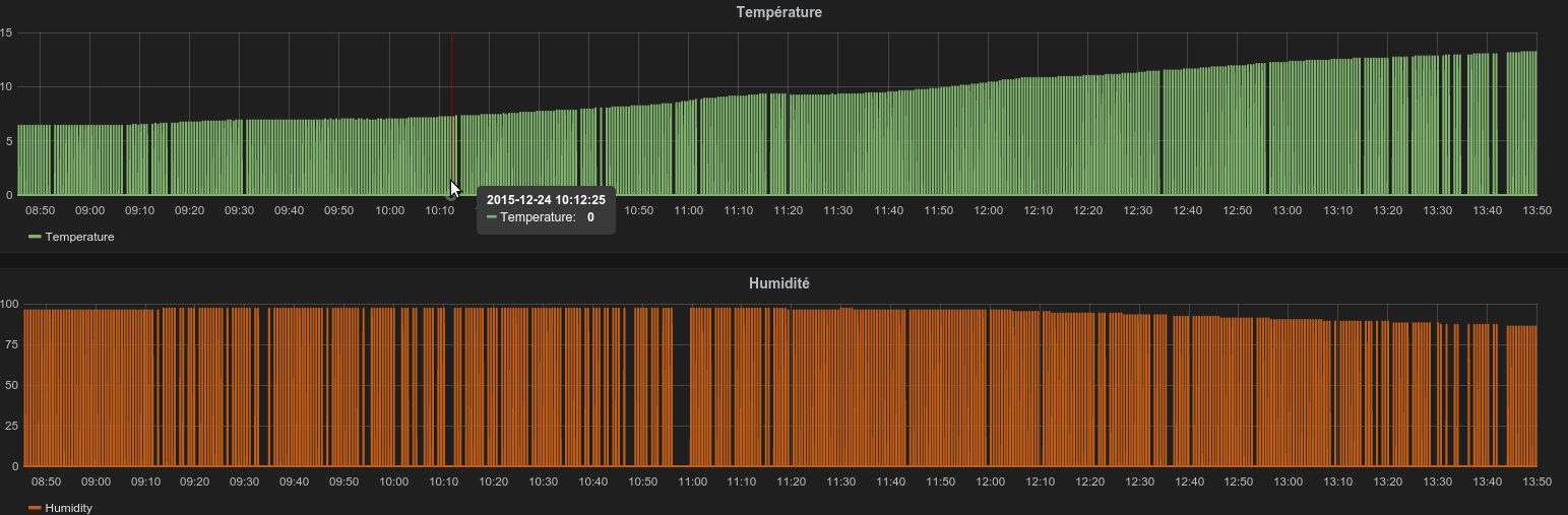
    24 hours of test fo eache setup. 0% of packet loss for the first setup. Lot of lost packet in the second setup especially during the day when the network is in use.
    I can try with UNO and W5100 if you want but I have same issue on ESP8266.
    For me I want to have someting simple to ensure acknoledge for destination. For temperature regulation or roller shutter it's very important. You can do it but it's not very easy.
    Example Yesterday with serial gateway
    Capture-1.png
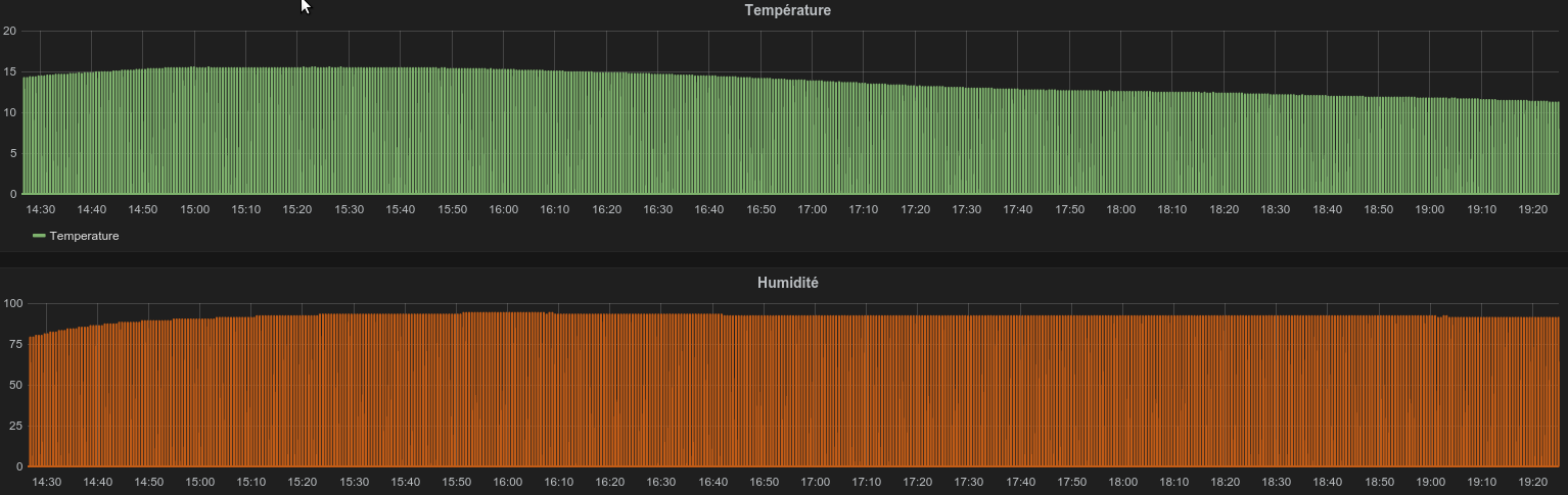
    And Today with IBoard
    Capture.png


  • Mod

    @Oitzu said:

    the mysensors ack flag but with automatic buffering and handling by the library

    Yes. There's the ack-flag, which is part of the nRF24L01+ chip, that automatically resends packets to the next node when a packet reception is not acknowledged. After a number of failed attempts the nRF24 will give up and return an error.
    On top of this is the MySensor's ack-flag which will track a message from source to destination and back again, even when the message gets routed by repeaters. The library however does not automatically resend a message which does not get ack'ed -- your application has to take care of this.
    For reliable communication the gateway, repeaters and sensor nodes all have to be able to buffer messages and automatically resend them. Depending on the maximum number of messages in transit simultaneously an ATMega328 will most likely not be able to buffer sufficient messages for a gateway or repeater node (too little ram).


  • Mod

    @Fabien So your network only consists of 1 node (sensebender) that sends every 30 seconds, and 1 gateway, correct?
    How many messages does the node produce every 30 seconds?

    The nRF24 is able to buffer upto 3 messages before it starts dropping packets, but I would have to dig into the MySensors/nRF24 code to see if these buffers are actually used.


  • @Fabien also interesting: how is the nrf24l01 pa/lna powered? You are talking about the same power supply on both boards, but are you powering the nrf directly from this power supply or from a onboard 3.3V regulator?
    Especially the pa/lna versions tends to be a little bit problematic especially on the maximum power setting.


  • I have implemented a resend if not received algorithm based on node-red.
    It is working only one way from controller/mqtt/gw -> node.
    The message will be resend after timeout in case if it is not acknowledged by a node. I can gather stats based on number of packets/lost per node. Even my RS485 nodes have a small packet loss. An average packet/command roundtrip (gw->node->gw) on radio is about 40-50ms, and 10-30ms on wired RS485 bus. Usually acknowledgement arrives after 50ms for sure - but some packets are received after 150ms and even after 250ms (who knows - maybe node is busy or gw). I am still testing this approach based on node-red. Seems to me the packets from gw to nodes are lost more frequently. One of my distant radio nodes loosing about 70% of messages 😞


  • My sensebender node is with default sketch so 2 messages (temp and hum). I just change MEASURE_INTERVAL and FORCE_TRANSMIT_INTERVAL. And yes the RFM is powered with onboard regulator.
    I will made another test with serial gateway sketch on Iboard. I will post results in few days. So the hardware will be exactly the same.


  • Mod

    @Fabien said:

    RFM

    One post you say NRF, now RFM... Which one are you actually using ❓ ❓ ❓


  • Sorry, I made my tests with NRF !


  • Mod

    @Fabien said:

    sensebender node is with default sketch so 2 messages (temp and hum)

    And a send of battery level every 60 runs of loop() (according to https://github.com/mysensors/Arduino/blob/master/libraries/MySensors/examples/SensebenderMicro/SensebenderMicro.ino)

    Anyway, that's 3 messages in total every 30 seconds. The nRF has a 3-message receive buffer, so when used correctly those 3 messages should just stay in that buffer waiting for the MySensors stack to retrieve them.

    Could you retry by changing the following line in your gateway code:

    gw.process();
    

    into

    gw.process();
    gw.process();
    gw.process();
    

    This will try to read 3 messages (the whole message buffer) at each run of the gateway loop().

    @hek I had a look at the MySensors code and have some doubts about following line: https://github.com/mysensors/Arduino/blob/master/libraries/MySensors/MySensor.cpp#L556
    Shouldn't the receive function be called repeatedly until no message is available anymore ? Now it will only read & process one message maximum on each gateway.process() call, while there could be up to 3 messages waiting in the fifo and new messages can come in while processing others.

    Furthermore I'm not sure of the code around https://github.com/mysensors/Arduino/blob/master/libraries/MySensors/utility/RF24.cpp#L878
    This listeningStarted flag seems to be used to force a delay of 800us after start listening, but the flag is not set when listening starts. In e.g. Thomas' nrf24 github repo (https://github.com/thozza/MySensors-Raspberry/blob/master/librf24-bcm/RF24.cpp#L527) the flag is set when listening starts and TMRh20 doesn't implement this delay (https://github.com/TMRh20/RF24/blob/master/RF24.cpp#L1067)
    Seems like we have some halve-merged code, but I wasn't able to track its origin (it was committed by you on 16 Sep 2014)


  • Admin

    @Yveaux
    Yep, might be good to dequeue the NRF fifo as fast as possible.

    Same goes for dev-branch
    https://github.com/mysensors/Arduino/blob/development/libraries/MySensors/core/MyTransport.cpp#L47
    Process should probably return true (when new message was available) and be "whiled" from here:
    https://github.com/mysensors/Arduino/blob/development/libraries/MySensors/core/MySensorCore.cpp#L52

    Hmm.. don't recognize the listeningStarted flag.. As you say.. Might be some half done refactoring... Let's ping @thozza .


  • Mod

    @Fabien Now I think about it; calling gw.process() three times in a row on the gateway will probably make no difference, as each gw.process() will end up in transmitting data to a remote server and block like it used to do...


  • Mod

    @hek said:

    Yep, might be good to dequeue the NRF fifo as fast as possible.

    Especially for a sleeping slave (which uses the same code as a gateway).


  • Admin

    @Hek: In the dev branch, _process() is called in main(): https://github.com/mysensors/Arduino/blob/development/libraries/MySensors/core/MyMainDefault.cpp#L12.
    As long as nodes are non-blocking and not sleeping, all queued messages are processed. However, for sleeping nodes we have to make sure the queue is processed before sending the node to sleep. The 800us delay code snippet (if correctly implemented) may help to stabilize the RF after switching to RX...


  • Ok so I continue my test with the same code. And you are right the sensebender send battery level every 30mins.
    For this test, I use exactly the same hardware and same wiring (including ethernet câble for both sketch). I will post result on monday (about 24h for each sketch).
    Serial sketch

      /**
     * The MySensors Arduino library handles the wireless radio link and protocol
     * between your home built sensors/actuators and HA controller of choice.
     * The sensors forms a self healing radio network with optional repeaters. Each
     * repeater and gateway builds a routing tables in EEPROM which keeps track of the
     * network topology allowing messages to be routed to nodes.
     *
     * Created by Henrik Ekblad <henrik.ekblad@mysensors.org>
     * Copyright (C) 2013-2015 Sensnology AB
     * Full contributor list: https://github.com/mysensors/Arduino/graphs/contributors
     *
     * Documentation: http://www.mysensors.org
     * Support Forum: http://forum.mysensors.org
     *
     * This program is free software; you can redistribute it and/or
     * modify it under the terms of the GNU General Public License
     * version 2 as published by the Free Software Foundation.
     *
     *******************************
     *
     * DESCRIPTION
     * The ArduinoGateway prints data received from sensors on the serial link. 
     * The gateway accepts input on seral which will be sent out on radio network.
     *
     * The GW code is designed for Arduino Nano 328p / 16MHz
     *
     * Wire connections (OPTIONAL):
     * - Inclusion button should be connected between digital pin 3 and GND  
     * - RX/TX/ERR leds need to be connected between +5V (anode) and digital pin 6/5/4 with resistor 270-330R in a series
     *
     * LEDs (OPTIONAL):
     * - To use the feature, uncomment MY_LEDS_BLINKING_FEATURE in MyConfig.h
     * - RX (green) - blink fast on radio message recieved. In inclusion mode will blink fast only on presentation recieved
     * - TX (yellow) - blink fast on radio message transmitted. In inclusion mode will blink slowly
     * - ERR (red) - fast blink on error during transmission error or recieve crc error 
     * 
     */
    
    // Enable debug prints to serial monitor
    #define MY_DEBUG 
    
    
    // Enable and select radio type attached
    #define MY_RADIO_NRF24
    //#define MY_RADIO_RFM69
    
    // Set LOW transmit power level as default, if you have an amplified NRF-module and
    // power your radio separately with a good regulator you can turn up PA level. 
    #define MY_RF24_PA_LEVEL RF24_PA_MAX
    
    #define MY_SOFTSPI
    #define MY_SOFT_SPI_SCK_PIN 7
    #define MY_SOFT_SPI_MISO_PIN 6
    #define MY_SOFT_SPI_MOSI_PIN 5
    #define MY_RF24_CE_PIN 3
    #define MY_RF24_CS_PIN 8
    
    // Enable serial gateway
    #define MY_GATEWAY_SERIAL
    
    // Flash leds on rx/tx/err
    //#define MY_LEDS_BLINKING_FEATURE
    // Set blinking period
    //#define MY_DEFAULT_LED_BLINK_PERIOD 300
    
    // Inverses the behavior of leds
    //#define MY_WITH_LEDS_BLINKING_INVERSE
    
    // Enable inclusion mode
    //#define MY_INCLUSION_MODE_FEATURE
    // Enable Inclusion mode button on gateway
    //#define MY_INCLUSION_BUTTON_FEATURE
    
    // Inverses behavior of inclusion button (if using external pullup)
    //#define MY_INCLUSION_BUTTON_EXTERNAL_PULLUP
    
    // Set inclusion mode duration (in seconds)
    //#define MY_INCLUSION_MODE_DURATION 60 
    // Digital pin used for inclusion mode button
    //#define MY_INCLUSION_MODE_BUTTON_PIN  3 
    
    //#define MY_DEFAULT_ERR_LED_PIN 4  // Error led pin
    //#define MY_DEFAULT_RX_LED_PIN  6  // Receive led pin
    //#define MY_DEFAULT_TX_LED_PIN  5  // the PCB, on board LED
    
    #include <SPI.h>
    #include <MySensor.h>  
    
    void setup() { 
      // Setup locally attached sensors
    }
    
    void presentation() {
     // Present locally attached sensors 
    }
    
    void loop() { 
      // Send locally attached sensor data here 
    }
    

    And Ethernet Sketch

      /**
     * The MySensors Arduino library handles the wireless radio link and protocol
     * between your home built sensors/actuators and HA controller of choice.
     * The sensors forms a self healing radio network with optional repeaters. Each
     * repeater and gateway builds a routing tables in EEPROM which keeps track of the
     * network topology allowing messages to be routed to nodes.
     *
     * Created by Henrik Ekblad <henrik.ekblad@mysensors.org>
     * Copyright (C) 2013-2015 Sensnology AB
     * Full contributor list: https://github.com/mysensors/Arduino/graphs/contributors
     *
     * Documentation: http://www.mysensors.org
     * Support Forum: http://forum.mysensors.org
     *
     * This program is free software; you can redistribute it and/or
     * modify it under the terms of the GNU General Public License
     * version 2 as published by the Free Software Foundation.
     *
     *******************************
     *
     * DESCRIPTION
     * The ArduinoGateway prints data received from sensors on the serial link. 
     * The gateway accepts input on seral which will be sent out on radio network.
     *
     * The GW code is designed for Arduino Nano 328p / 16MHz
     *
     * Wire connections (OPTIONAL):
     * - Inclusion button should be connected between digital pin 3 and GND  
     * - RX/TX/ERR leds need to be connected between +5V (anode) and digital pin 6/5/4 with resistor 270-330R in a series
     *
     * LEDs (OPTIONAL):
     * - To use the feature, uncomment MY_LEDS_BLINKING_FEATURE in MyConfig.h
     * - RX (green) - blink fast on radio message recieved. In inclusion mode will blink fast only on presentation recieved
     * - TX (yellow) - blink fast on radio message transmitted. In inclusion mode will blink slowly
     * - ERR (red) - fast blink on error during transmission error or recieve crc error 
     * 
     */
    
    // Enable debug prints to serial monitor
    #define MY_DEBUG 
    
    
    // Enable and select radio type attached
    #define MY_RADIO_NRF24
    //#define MY_RADIO_RFM69
    
    // Set LOW transmit power level as default, if you have an amplified NRF-module and
    // power your radio separately with a good regulator you can turn up PA level. 
    #define MY_RF24_PA_LEVEL RF24_PA_MAX
    
    #define MY_GATEWAY_W5100
    
    #define MY_SOFTSPI
    #define MY_SOFT_SPI_SCK_PIN 7
    #define MY_SOFT_SPI_MISO_PIN 6
    #define MY_SOFT_SPI_MOSI_PIN 5
    #define MY_RF24_CE_PIN 3
    #define MY_RF24_CS_PIN 8
    
    #define MY_IP_ADDRESS 192,168,2,200   // If this is disabled, DHCP is used to retrieve address
    // Renewal period if using DHCP
    //#define MY_IP_RENEWAL_INTERVAL 60000
    // The port to keep open on node server mode / or port to contact in client mode
    #define MY_PORT 5003      
    
    // Controller ip address. Enables client mode (default is "server" mode). 
    // Also enable this if MY_USE_UDP is used and you want sensor data sent somewhere. 
    //#define MY_CONTROLLER_IP_ADDRESS 192, 168, 178, 254   
     
    // The MAC address can be anything you want but should be unique on your network.
    // Newer boards have a MAC address printed on the underside of the PCB, which you can (optionally) use.
    // Note that most of the Ardunio examples use  "DEAD BEEF FEED" for the MAC address.
    #define MY_MAC_ADDRESS 0xDE, 0xAD, 0xBE, 0xEF, 0xFE, 0xED
    
    // Enable serial gateway
    //#define MY_GATEWAY_SERIAL
    
    // Flash leds on rx/tx/err
    //#define MY_LEDS_BLINKING_FEATURE
    // Set blinking period
    //#define MY_DEFAULT_LED_BLINK_PERIOD 300
    
    // Inverses the behavior of leds
    //#define MY_WITH_LEDS_BLINKING_INVERSE
    
    // Enable inclusion mode
    //#define MY_INCLUSION_MODE_FEATURE
    // Enable Inclusion mode button on gateway
    //#define MY_INCLUSION_BUTTON_FEATURE
    
    // Inverses behavior of inclusion button (if using external pullup)
    //#define MY_INCLUSION_BUTTON_EXTERNAL_PULLUP
    
    // Set inclusion mode duration (in seconds)
    //#define MY_INCLUSION_MODE_DURATION 60 
    // Digital pin used for inclusion mode button
    //#define MY_INCLUSION_MODE_BUTTON_PIN  3 
    
    //#define MY_DEFAULT_ERR_LED_PIN 4  // Error led pin
    //#define MY_DEFAULT_RX_LED_PIN  6  // Receive led pin
    //#define MY_DEFAULT_TX_LED_PIN  5  // the PCB, on board LED
    
    #include <SPI.h>
    #include <Ethernet.h>
    #include <MySensor.h>  
    
    void setup() { 
      // Setup locally attached sensors
    }
    
    void presentation() {
     // Present locally attached sensors 
    }
    
    void loop() { 
      // Send locally attached sensor data here 
    }


  • After 2 days of test. I lost few packets (5 or 6 in 24 hours and usually humidity ...). I will perform another test after changing all my ethernet câbles.


Log in to reply
 

Suggested Topics

0
Online

11.2k
Users

11.1k
Topics

112.5k
Posts