Drive household SSR with SSR and Arduino
-
I need a bit of advice here please.
Long story short : what are the limitations for driving an SSR with an SSR ?
Long story : I have an AC ceiling light powered by a DinRail Relay (latching relay module ?). That relay is driven by numerous 240V AC wall switches as per following drawing.

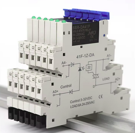
Then enters MySensors!! Arduino and chineese SSR (input 3 to 32V DC, output AC 240V).
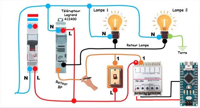
DinRail relay still reacts with wall switches but not with Arduino+SSR...
Fun fact : multimeter reads 150V at wall switch contacts (between orange and red line). This setup has been working flawlessly until now so i guess it is normal behaviour.I have read somewhere that these SSRs (based on triacs) only switch on when load voltage gets to zero... i'm not sure i fully understand and i am here asking you whether that's the reason why it doesn't work as expected and what would be the way to get this right.
Thanks a lot for your input !
-
It seems you should be able to do that. I found this, "Voltage/Current Matching: The control output of the first SSR must match the required input voltage (and current) of the second SSR's control side." Most likely there is insufficient load on the output of the Arduino driven SSR to have it function.
Why not use a mechanical relay? The current you would be switching would be very, very small which means the relay would last a very long time.
@OldSurferDude thanks a lot for your input.
You are right. I remember reading this as well. SSRs need a minimal load on output side in order to latch properly
I chose these relays because of noise: the electric cabinet for circuit breakers and relays is located next to the bedroom. At first cabinet was filed with mechanical 240V AC relays 😂 🤯
I will have a second try with the tiny Omron Chinese clones, in case they need much less load to latch properly.
Thanks a lot for you help 👍🏻
I’ll come back here to conclude (either Omron SSRs or mech style relays). -
I just did a google search and found that the Legrand 4124 00 is a (noiseless) latching relay and the input is referred to as a "coil". This means to me that it is a mechanical relay, not an SSR. You should be able to drive it with an SSR.
Now the latching part. The Legrand 4124 00 needs a "pulse". It appears that the switch you are replacing is a push button, (closed only while holding the switch). This means that your Arduino must
pulse the SSR, turn it on and then, a second or two later, turn it off.Is that what you are doing?
Unfortunately, your Arduino won't know if the light is on or off.
--------- other thoughts but not very good ones
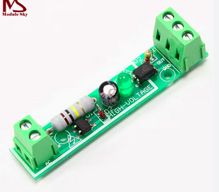
According to this article, SSR's inputs are opto-isolators. If I read the specifications correctly, the input voltage is less than 0.1V (<100m) and the short circuit current is 50mA.This means that you may be able to drive your Télérupteur Legrand with another optoisolator (for example PC817) which is driven by your Arduino. (The specs say that the input to the optoisolator needs 50mA, the Arduino specs state that it can only supply 40mA, but I have had success with doing it)
BUT You have measured Retour BP to L at 150V. The optoisolator I note cannot handle 80V Collector to emitter but only 6V emitter to collector.
Which led me to what I wrote above.
-
I just did a google search and found that the Legrand 4124 00 is a (noiseless) latching relay and the input is referred to as a "coil". This means to me that it is a mechanical relay, not an SSR. You should be able to drive it with an SSR.
Now the latching part. The Legrand 4124 00 needs a "pulse". It appears that the switch you are replacing is a push button, (closed only while holding the switch). This means that your Arduino must
pulse the SSR, turn it on and then, a second or two later, turn it off.Is that what you are doing?
Unfortunately, your Arduino won't know if the light is on or off.
--------- other thoughts but not very good ones
According to this article, SSR's inputs are opto-isolators. If I read the specifications correctly, the input voltage is less than 0.1V (<100m) and the short circuit current is 50mA.This means that you may be able to drive your Télérupteur Legrand with another optoisolator (for example PC817) which is driven by your Arduino. (The specs say that the input to the optoisolator needs 50mA, the Arduino specs state that it can only supply 40mA, but I have had success with doing it)
BUT You have measured Retour BP to L at 150V. The optoisolator I note cannot handle 80V Collector to emitter but only 6V emitter to collector.
Which led me to what I wrote above.
@OldSurferDude
Thanks a lot for your time. I am very impressed by the amount of research !!In the end I still can not confirm whether this relay is noiseless/mechanical or just based on electronic components (triacs).
Good news is that this Legrand noiseless relay can be driven by a mechanical relay or by a tiny SSR. I chose a SSR unit with a DinRail mount. Looks all very professional in the electrical cabinet.
I have also added an optocoupler to check the state of the light and sent it back to openHab: input is connected to lightbulb wires and signal is connected to Arduino. Works all fine!!
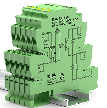
Next step is to receive optocoupler with DinRail mount !!
-
Great! You got it to work! And it looks professional, too! Good job!
-
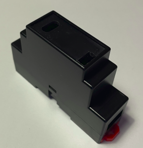
Quick update: i wanted to hide and protect the Nano in a housing.
Aliexpress supplies very nice enclosures that fits on Din rails.
https://fr.aliexpress.com/item/1005005505247992.htmlThey fit in electrical cabinets thanks to standard dimensions.

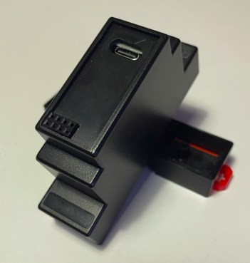
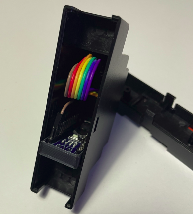
One 3Dprinted part later (glued inside enclosure) and the Arduino is safely held in place!
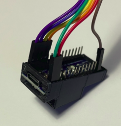
stl file of adapter :
dinRailEnclosureMountForNano-revE.stl
Hello! It looks like you're interested in this conversation, but you don't have an account yet.
Getting fed up of having to scroll through the same posts each visit? When you register for an account, you'll always come back to exactly where you were before, and choose to be notified of new replies (either via email, or push notification). You'll also be able to save bookmarks and upvote posts to show your appreciation to other community members.
With your input, this post could be even better 💗
Register Login