My Sensor node "motherboard" (MySensorsNode)
-
EDIT: BOMs are now uploaded as well. I have to inspect the gerbers one more time but it is close to manufacture now :)
-
@Anticimex: thx. you have made a great work on this, lot of research I imagine :)
I will look at it carefully, maybe there are interesting ref :wink:
:+1: -
Thanks,
well at least there are a lot of sourcing alternatives now :) -
sure!
just a little question, how do you plan to add daughter board on your smallest board? on bottom? -
No, on top with some form of riser-board so it goes above the Arduino. If I ever bother. My sensors are socketed so I could just plug them directly onto the connector for that board variant or use extension wires for them.
-
oki, cool :smile:
-
The small 5x5 board I did most like a favor to anyone who would like to buy a few cheap ones (they are dirt cheap on DirtyPCBs, I will put a order-link to it when I have sent them for manufacture). I will use the board-specific layouts for my "real" sensors since they are tuned to the enclosures I plan to use. Hopefully I got my measurements right...but the 5x5 board will serve as my second prototype run before I tape out the "real" ones. Just so I can verify the design once more before I start deploying my actual sensor network. Took a few years but now I have all my personal "must haves" in place (security and features) so I am ready :D
The boards also have the external flash so I can handle any OTA bootloader variant and it supports both radios in through-hole variants so I can put sockets to easily swap radios later on as well. And I already ordered the 2mm pitch sockets for the RF69 so that is already done. -
I totally agree with your vision. your board, you know it, is great, a swiss army knife, useful :smiley:
and I am rather like you, meaning I hope I will start soon my "real" network too. can't wait! but like you said it takes so long time to study, dev and tests...
but it is so fun when it works :) -
The ultimate satisfaction is to tinker with it, test, improve, optimize, and then deploy and nail it from the start :)
-
yeah :smiley:
do you plan in future to invest in 3d printer? I am looking at this actually, too much tempting...
-
I was considering it for a while, but realised that I don't have the time for that unfortunately :(
And I am a total novice in 3D design, so I would also need to invest a lot in learning that as well. So I boldly decided to go for off-the-shelf products, or leech other peoples designes through 3dhubs :) -
yes I understand. we're always running after time...too bad to have to sleep :laughing:
I hope we will see lots of 3d design share in the future. to have a good opensource collection hardware, sketch, 3d design...it could be great! -
EDIT: I have "released" the 1.1 board in github and updated the top post to link to the releases.
Current status is that 1.1 is released as it is shipped to the manufacturer and current status is unverified (as I have not received the boards yet). It also currently only covers the 5x5 boards as I intend to verify that one before manufacturing the BOX-boards. -
I think this board is perfect but is it possible to modify it so that you have the option to replace the battery for a HLK-PM01 if wanting to use direct power ?
-
I think this board is perfect but is it possible to modify it so that you have the option to replace the battery for a HLK-PM01 if wanting to use direct power ?
@Cliff-Karlsson thanks! No, I'm not interested in that. I don't think that part would fit in my boxes. But as I have published all sources and cad files in an "open" format, and picked a license that permits derivative work, you are free to copy my board and add that, given that you follow the license :)
-
@Cliff-Karlsson : If the board below is tested (still on it's way from DirtyPCB to me), I will post the EAGLE files. This board allows several types of powering: battery (AAA), external battery (with DC regulator), direct 5V (if you mount the 3V3 LDO for the radio), HLK-PM01 for direct 120-220V AC. I need to test the various setups before I publish this, but a preview of the board is here:
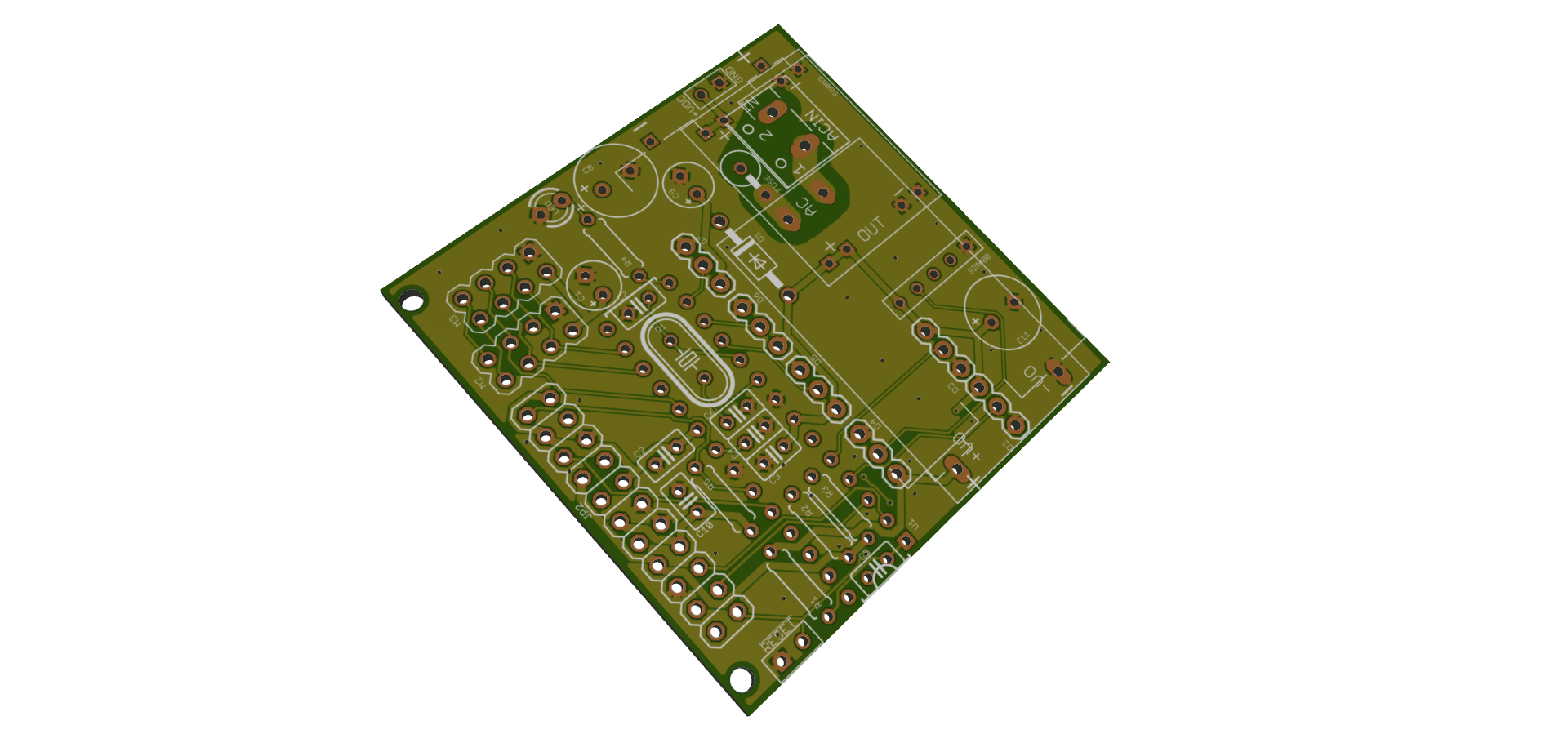
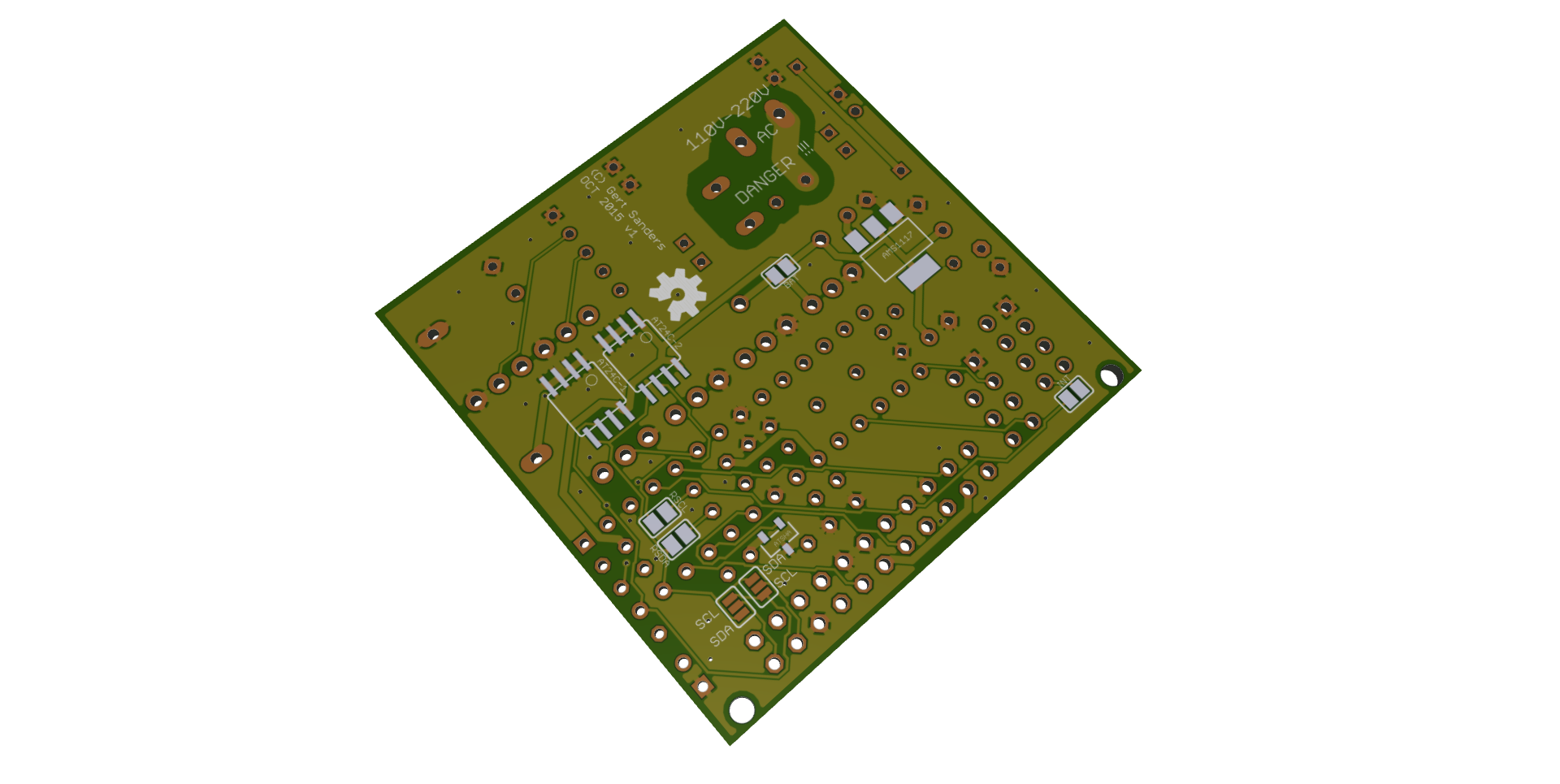
-
@GertSanders said:
tested (still on it's way from DirtyPCB to me), I will post the EAGLE files. This board allows several types of powering: battery (AAA), external battery (with DC regulator), dir
Great, is it possible to use a RFM69? And do you solder an atmega (?) chip on to it or do you add a pro mini?
Hello! It looks like you're interested in this conversation, but you don't have an account yet.
Getting fed up of having to scroll through the same posts each visit? When you register for an account, you'll always come back to exactly where you were before, and choose to be notified of new replies (either via email, or push notification). You'll also be able to save bookmarks and upvote posts to show your appreciation to other community members.
With your input, this post could be even better 💗
Register Login