MySensors shield and RGBW Controller
-
@LastSamurai You have an error on your RGBW board! The PWM pins for a Pro Mini are not 3,4,5 and 6! They should be according to this:
PWM: 3, 5, 6, 9, 10, and 11. Provide 8-bit PWM output with the analogWrite() function.
@korttoma said:
@LastSamurai You have an error on your RGBW board! The PWM pins for a Pro Mini are not 3,4,5 and 6! They should be according to this:
PWM: 3, 5, 6, 9, 10, and 11. Provide 8-bit PWM output with the analogWrite() function.
Ah yes, thanks for the reminder! I knew this at design time (though I forgot it myselft now). Pins 9-11 are already used by the nrf module, so there aren't enough pins left for 4x PWM. RGB channels are using the pins 3,5,6 in my design and white the "normal" pin 4. This isn't a huge problem because at least in domitcz all that the white channel does is on/off anyways (or mostly). I guess I have to update the texts though.
Do you guys know if there is a way to free up one additional pwm pin so that true 4 way pwm is possible? If thats not possible there is software pwm (although that might be a problem when using the network..?!).
@jeti For my tests I am using IRFZ44N, but that really only depends on how many leds you want to be able to drive.
-
@korttoma said:
@LastSamurai You have an error on your RGBW board! The PWM pins for a Pro Mini are not 3,4,5 and 6! They should be according to this:
PWM: 3, 5, 6, 9, 10, and 11. Provide 8-bit PWM output with the analogWrite() function.
Ah yes, thanks for the reminder! I knew this at design time (though I forgot it myselft now). Pins 9-11 are already used by the nrf module, so there aren't enough pins left for 4x PWM. RGB channels are using the pins 3,5,6 in my design and white the "normal" pin 4. This isn't a huge problem because at least in domitcz all that the white channel does is on/off anyways (or mostly). I guess I have to update the texts though.
Do you guys know if there is a way to free up one additional pwm pin so that true 4 way pwm is possible? If thats not possible there is software pwm (although that might be a problem when using the network..?!).
@jeti For my tests I am using IRFZ44N, but that really only depends on how many leds you want to be able to drive.
@LastSamurai To free up an additional pin for PWM, I believe you can change the CE and CS pins in the GW constructor. Use pin 4 for for CE to the radio and reroute the MOSFET to pin 9. And then designate the change in the GW constructor:
MyTransportNRF24 transport(4, 10);
MySensor gw(transport); -
@Dwalt is absolutely right. I have been using this kind of setup for a looong time allready.
-
I finally found the time to really test my RGBW boards and I found another error: 2 pins of the mosfets are switched. To test it anyways I just took the mosfets and bend some legs to get them to the right connectors on the pcb. Aside from that I tested it for some days and it works beautifully. Dimming, on/off, color changing and the rgb/white switching works.
I will try to create a second version soon that uses 4 pwm pins (so that white can be dimmed to) and fixes the mosfet's pins. Perhaps i'll switch to a barebone atmega 328p too because the full pro mini is kinda overkill here and I might be able to make smaller pcbs then.After I found out that my problems with programming the pro minis comes from FTDI's newest driver "features" (always prints "NON GENUINE DEVICE FOUND!" on the serial port) I can now also try my normal sensors boards again with some low power modifications.
What's annoying me at the moment is that my raspberry pi (running my domoticz) controller won't restart at the moment. I'll have to fix that first.
As always any input is welcome and I'll try to post updates and pictures as soon as possible.
-
Good news (I guess ;) ). I already redid my raspberry pi controller (where I kinda killed the old sd card :expressionless: ) and also fixed the 2 errors in my pcb.
Sometimes in the next few days I'll try out a smaller pcb with the barebone arduino and test my sensor nodes again. -
hi,
nice work,
I not understand why you said 2 pins of the mosfets are switched, for me it's ok,
I see G to arduino pins, S at center, and D to leds.. I miss something ?
I think I will buy some of them for testingps: maybe you can add your project on openhardware.io
sry for my english
-
hi,
nice work,
I not understand why you said 2 pins of the mosfets are switched, for me it's ok,
I see G to arduino pins, S at center, and D to leds.. I miss something ?
I think I will buy some of them for testingps: maybe you can add your project on openhardware.io
sry for my english
@vil1driver Thanks you! I did change them to IRFZ44N's to be able to drive longer strips. I think the new schematics aren't uploaded here yet. I did switch drain and source pins there. Other than that it seems to be working perfectly, so I will create a new (and hopefully final) version soon.
I am also thinking about adding SPI pins. Perhaps I also add pins for a DHT11/22, there is still some free space on there. Does anyone have another idea what would be good to add/change?
As soon as the updated PCB is done I will update my github and I guess also open a project on openhardware.io.
-
I just finished building another prototype and it's mostly working fine. I still have some lag/network issues and I am not 100% sure about the perfect software/dimming either but I am working on that.
I will update the code in my git soon and design the new board (I am trying to learn using kicad for that).With the RGBW strip I am using red seems to be a lot darker than the other colors. Has someone seen similar behaviour? Or an idea how to fix that?
-
The problem with the red channel seems to be on the controller's side. Once I switches red and green wires the green got dimmed way too much. I am not sure yet if i's software or hardware thats causing the problem though. :worried:
I now have a real demo up and running and found another problem: most of the time sending commands works but about 20-40% of the command simply get ignored. Once that happens it takes some time to react at all again.
On/off seems to work most of the time, changing colors slightly less, changing to/from white most of the time doesn't and dimming doesn't seem to work at all. It is really strange.
Also the domoticz webinterface gets really laggy after some of the commands failed.
Waiting some time and then retrying seems to help.Is there a good way to debug the domoticz/serial gateway part of the network (because the rgbw controller worked well when I tested it before). The domoticz log only gives me entries like this:
2016-03-12 18:23:46.917 (MySensors USB-Serial Gateway) Lighting Limitless/Applamp (RGBW test light)and I have no idea how to see what the serial output to the gateway is.
Can anyone help?
The updated code is in my github and here. If you find errors or stuff that could be improved please tell me :)
/**
Based on the MySensors Project: http://www.mysensors.org

This sketch controls a (analog)RGBW strip by listening to new color values from a (domoticz) controller and then fading to the new color.

Version 0.9

TODO
safe/request values after restart/loss of connection
*/


#define SN   "RGBW Led strip testSketch 3"
#define SV   "v0.9"

// Load mysensors library
#include <MySensor.h>
// Load Serial Peripheral Interface library
#include <SPI.h>

// Arduino pin attached to driver pins
#define RED_PIN 3
#define WHITE_PIN 4
#define GREEN_PIN 5
#define BLUE_PIN 6
#define NUM_CHANNELS 4 // how many channels, RGBW=4 RGB=3...

#define SENSOR_ID 1

// Smooth stepping between the values
#define STEP 1
#define INTERVAL 10
const int pwmIntervals = 255;
float R; // equation for dimming curve


MySensor gw;

// Stores the current color settings
byte channels[4] = {RED_PIN, GREEN_PIN, BLUE_PIN, WHITE_PIN};
byte values[4] = {100, 100, 100, 100};
byte target_values[4] = {100, 100, 100, 100};


// stores dimming level
byte dimming = 100;
byte target_dimming = 100;

// tracks if the strip should be on of off
boolean isOn = true;

// time tracking for updates
unsigned long lastupdate = millis();

void setup()
{
  // Initializes the sensor node (with callback function for incoming messages)
  gw.begin(incomingMessage, 123);	// 123 = node id for testing

  // Present sketch (name, version)
  gw.sendSketchInfo(SN, SV);

  // Register sensors (id, type, description, ack back)
  gw.present(SENSOR_ID, S_RGBW_LIGHT, "RGBW test light", true);

  // Set all channels to output (pin number, type)
  for (int i = 0; i < NUM_CHANNELS; i++) {
    pinMode(channels[i], OUTPUT);
  }

  // set up dimming
  R = (pwmIntervals * log10(2))/(log10(255));

  // init lights
  updateLights();

  // debug
  if (isOn) {
    Serial.println("RGBW is running...");
  }

  Serial.println("Waiting for messages...");
}

void loop()
{
  // Process incoming messages (like config and light state from controller) - basically keep the mysensors protocol running
  gw.process();

  // and set the new light colors
  if (millis() > lastupdate + INTERVAL) {
    updateLights();
    lastupdate = millis();
  }
}

// callback function for incoming messages
void incomingMessage(const MyMessage &message) {

  Serial.print("Got a message - ");
  Serial.print("Messagetype is: ");
  Serial.println(message.type);

  // acknoledgment
  if (message.isAck())
  {
   	Serial.println("Got ack from gateway");
  }

  // new dim level
  else if (message.type == V_DIMMER) {
      Serial.println("Dimming to ");
      Serial.println(message.getString());
      target_dimming = message.getByte();
  }

  // on / off message
  else if (message.type == V_STATUS) {
    Serial.print("Turning light ");

    isOn = message.getInt();

    if (isOn) {
      Serial.println("on");
    } else {
      Serial.println("off");
    }
  }

  // new color value
  else if (message.type == V_RGBW) {
    const char * rgbvalues = message.getString();
    inputToRGBW(rgbvalues);
  }
}

// this gets called every INTERVAL milliseconds and updates the current pwm levels for all colors
void updateLights() {

  // update pin values -debug
  //Serial.println(greenval);
  //Serial.println(redval);
  //Serial.println(blueval);
  //Serial.println(whiteval);

  //Serial.println(target_greenval);
  //Serial.println(target_redval);
  //Serial.println(target_blueval);
  //Serial.println(target_whiteval);
  //Serial.println("+++++++++++++++");

  // for each color
  for (int v = 0; v < NUM_CHANNELS; v++) {

    if (values[v] < target_values[v]) {
      values[v] += STEP;
      if (values[v] > target_values[v]) {
        values[v] = target_values[v];
      }
    }

    if (values[v] > target_values[v]) {
      values[v] -= STEP;
      if (values[v] < target_values[v]) {
        values[v] = target_values[v];
      }
    }
  }

  // dimming
  if (dimming < target_dimming) {
    dimming += STEP;
    if (dimming > target_dimming) {
      dimming = target_dimming;
    }
  }
  if (dimming > target_dimming) {
    dimming -= STEP;
    if (dimming < target_dimming) {
      dimming = target_dimming;
    }
  }

  /*
  // debug - new values
  Serial.println(greenval);
  Serial.println(redval);
  Serial.println(blueval);
  Serial.println(whiteval);

  Serial.println(target_greenval);
  Serial.println(target_redval);
  Serial.println(target_blueval);
  Serial.println(target_whiteval);
  Serial.println("+++++++++++++++");
  */

  // set actual pin values
  for (int i = 0; i < NUM_CHANNELS; i++) {
    if (isOn) {
      //analogWrite(channels[i], dimming / 100 * values[i]);
      // non linear fading, idea from https://diarmuid.ie/blog/pwm-exponential-led-fading-on-arduino-or-other-platforms/
      analogWrite(channels[i], pow (2, (values[i] / R)) - 1);
    } else {
      analogWrite(channels[i], 0);
    }
  }
}

// converts incoming color string to actual (int) values
// ATTENTION this currently does nearly no checks, so the format needs to be exactly like domoticz sends the strings
void inputToRGBW(const char * input) {
  Serial.print("Got color value of length: ");
  Serial.println(strlen(input));

  if (strlen(input) == 6) {
    Serial.println("new rgb value");
    target_values[0] = fromhex (& input [0]);
    target_values[1] = fromhex (& input [2]);
    target_values[2] = fromhex (& input [4]);
    target_values[3] = 0;
  } else if (strlen(input) == 9) {
    Serial.println("new rgbw value");
    target_values[0] = fromhex (& input [1]); // ignore # as first sign
    target_values[1] = fromhex (& input [3]);
    target_values[2] = fromhex (& input [5]);
    target_values[3] = fromhex (& input [7]);
  } else {
    Serial.println("Wrong length of input");
  }


  Serial.print("New color values: ");
  Serial.println(input);

  for (int i = 0; i < NUM_CHANNELS; i++) {
    Serial.print(target_values[i]);
    Serial.print(", ");
  }

  Serial.println("");
  Serial.print("Dimming: ");
  Serial.println(dimming);
}

// converts hex char to byte
byte fromhex (const char * str)
{
  char c = str [0] - '0';
  if (c > 9)
    c -= 7;
  int result = c;
  c = str [1] - '0';
  if (c > 9)
    c -= 7;
  return (result << 4) | c;
}
Update:
fixed some small errors in the code.
I also just debugged the rgbw controller via serial to usb and the problem seems to be that most commands just don't reach the node. At least I got no errors via serial.
There also seems to be some kind of jam sometimes where I send multiple commands nothing happens and then after some seconds all of them are executed in very short order -
So I did some more debugging. If someone else has similar problems: you can see the serial output if you ssh into your pi and type
cat /dev/ttyACM0where ttyACM0 is the serial port of my gateway. The problem seems to be somewhere between gateway and rgbw controller.
I get a log like this:0;0;3;0;9;send: 0-0-123-123 s=1,c=1,t=2,pt=0,l=1,sg=0,st=fail:1 0;0;3;0;9;read: 123-123-0 s=1,c=1,t=2,pt=0,l=1,sg=0:1 123;1;1;1;2;1 0;0;3;0;9;send: 0-0-123-123 s=1,c=1,t=2,pt=0,l=1,sg=0,st=fail:1 0;0;3;0;9;send: 0-0-123-123 s=1,c=1,t=2,pt=0,l=1,sg=0,st=fail:0 0;0;3;0;9;send: 0-0-123-123 s=1,c=1,t=2,pt=0,l=1,sg=0,st=fail:1 0;0;3;0;9;send: 0-0-123-123 s=1,c=1,t=2,pt=0,l=1,sg=0,st=fail:1 0;0;3;0;9;send: 0-0-123-123 s=1,c=1,t=2,pt=0,l=1,sg=0,st=fail:0 0;0;3;0;9;send: 0-0-123-123 s=1,c=1,t=2,pt=0,l=1,sg=0,st=ok:1 0;0;3;0;9;send: 0-0-123-123 s=1,c=1,t=2,pt=0,l=1,sg=0,st=fail:0 0;0;3;0;9;read: 123-123-0 s=1,c=1,t=2,pt=0,l=1,sg=0:0 123;1;1;1;2;0 0;0;3;0;9;send: 0-0-123-123 s=1,c=1,t=2,pt=0,l=1,sg=0,st=fail:1 0;0;3;0;9;send: 0-0-123-123 s=1,c=1,t=2,pt=0,l=1,sg=0,st=ok:0 0;0;3;0;9;read: 123-123-0 s=1,c=1,t=2,pt=0,l=1,sg=0:0 123;1;1;1;2;0 0;0;3;0;9;send: 0-0-123-123 s=1,c=1,t=2,pt=0,l=1,sg=0,st=ok:1 0;0;3;0;9;read: 123-123-0 s=1,c=1,t=2,pt=0,l=1,sg=0:1 123;1;1;1;2;1 0;0;3;0;9;send: 0-0-123-123 s=1,c=1,t=2,pt=0,l=1,sg=0,st=fail:0 0;0;3;0;9;read: 123-123-0 s=1,c=1,t=2,pt=0,l=1,sg=0:0 123;1;1;1;2;0 0;0;3;0;9;send: 0-0-123-123 s=1,c=1,t=2,pt=0,l=1,sg=0,st=fail:1 0;0;3;0;9;send: 0-0-123-123 s=1,c=1,t=2,pt=0,l=1,sg=0,st=fail:0 0;0;3;0;9;send: 0-0-123-123 s=1,c=1,t=2,pt=0,l=1,sg=0,st=fail:1 0;0;3;0;9;send: 0-0-123-123 s=1,c=1,t=2,pt=0,l=1,sg=0,st=fail:0 0;0;3;0;9;send: 0-0-123-123 s=1,c=1,t=2,pt=0,l=1,sg=0,st=fail:1 0;0;3;0;9;send: 0-0-123-123 s=1,c=1,t=2,pt=0,l=1,sg=0,st=fail:0 0;0;3;0;9;send: 0-0-123-123 s=1,c=1,t=2,pt=0,l=1,sg=0,st=fail:1 0;0;3;0;9;send: 0-0-123-123 s=1,c=1,t=2,pt=0,l=1,sg=0,st=fail:0 0;0;3;0;9;read: 123-123-0 s=1,c=1,t=2,pt=0,l=1,sg=0:0 123;1;1;1;2;0 0;0;3;0;9;send: 0-0-123-123 s=1,c=1,t=2,pt=0,l=1,sg=0,st=fail:1 0;0;3;0;9;send: 0-0-123-123 s=1,c=1,t=2,pt=0,l=1,sg=0,st=ok:0 0;0;3;0;9;read: 123-123-0 s=1,c=1,t=2,pt=0,l=1,sg=0:0 123;1;1;1;2;0 0;0;3;0;9;send: 0-0-123-123 s=1,c=1,t=2,pt=0,l=1,sg=0,st=fail:1 0;0;3;0;9;read: 123-123-0 s=1,c=1,t=2,pt=0,l=1,sg=0:1 123;1;1;1;2;1 0;0;3;0;9;send: 0-0-123-123 s=1,c=1,t=2,pt=0,l=1,sg=0,st=fail:1 0;0;3;0;9;send: 0-0-123-123 s=1,c=1,t=41,pt=0,l=9,sg=0,st=fail:#00000 0;0;3;0;9;read: 123-123-0 s=1,c=1,t=41,pt=0,l=9,sg=0:#000000FF 123;1;1;1;41;#000000FF 0;0;3;0;9;send: 0-0-123-123 s=1,c=1,t=3,pt=0,l=3,sg=0,st=fail:100 0;0;3;0;9;send: 0-0-123-123 s=1,c=1,t=2,pt=0,l=1,sg=0,st=fail:0 0;0;3;0;9;read: 123-123-0 s=1,c=1,t=2,pt=0,l=1,sg=0:0 123;1;1;1;2;0 0;0;3;0;9;send: 0-0-123-123 s=1,c=1,t=2,pt=0,l=1,sg=0,st=fail:1 0;0;3;0;9;read: 123-123-0 s=1,c=1,t=2,pt=0,l=1,sg=0:1 123;1;1;1;2;1Every action in the webinterface get a entry here and some of them work just fine. But most of them return st=fail:1 (which I guess means that the message couldn't reach the receiver). In some cases it seems like only the acknoledgment didn't make it because the rgbwcontroller reacts anyways.
Any ideas how to fix that? I had none such problems earlier with my sensor nodes. Might this be a software problem with my controller? Am I not updating gw.process() often enough? -
Hi @LastSamurai, I've loaded your sketch onto my RGBW controller, and had a look.
I discovered a number of issues:
- in updateLights(), under '// for each color', the limit on the 'for' loop should be v < NUM_CHANNELS (not v<= ... - this was corrupting channels[0])
- under '// set actual pin values', I had trouble with the exponential dimming, so I commented out this line, and uncommented the alternative analogWrite statement 2 lines above
- dimming and target_dimming should be declared as type 'float', otherwise the calculation dimming / 100 * values[i] rounds down to zero (the LEDs were switching off)
- on an Arduino Nano and Pro Mini (at least), PWM outputs are restricted to D3, 5, 6, 9, 10, 11 - you have defined WHITE_PIN as D4.
With these changes, it seems to work OK - I didn't get any 'st=fail' errors; are you supplying the radio from a separate 3.3V supply (not from the Arduino), and have you added a capacitor (usually 4.7uF) across the supply pins?
-
Hi @LastSamurai, I've loaded your sketch onto my RGBW controller, and had a look.
I discovered a number of issues:
- in updateLights(), under '// for each color', the limit on the 'for' loop should be v < NUM_CHANNELS (not v<= ... - this was corrupting channels[0])
- under '// set actual pin values', I had trouble with the exponential dimming, so I commented out this line, and uncommented the alternative analogWrite statement 2 lines above
- dimming and target_dimming should be declared as type 'float', otherwise the calculation dimming / 100 * values[i] rounds down to zero (the LEDs were switching off)
- on an Arduino Nano and Pro Mini (at least), PWM outputs are restricted to D3, 5, 6, 9, 10, 11 - you have defined WHITE_PIN as D4.
With these changes, it seems to work OK - I didn't get any 'st=fail' errors; are you supplying the radio from a separate 3.3V supply (not from the Arduino), and have you added a capacitor (usually 4.7uF) across the supply pins?
Thank you very much for testing!!
I did already fix some of these errors in the code above and my git... but I forgot to push that to github :sweat_smile:@MikeF said:
Hi @LastSamurai, I've loaded your sketch onto my RGBW controller, and had a look.
I discovered a number of issues:
- in updateLights(), under '// for each color', the limit on the 'for' loop should be v < NUM_CHANNELS (not v<= ... - this was corrupting channels[0])
I already fixed that
- under '// set actual pin values', I had trouble with the exponential dimming, so I commented out this line, and uncommented the alternative analogWrite statement 2 lines above
Mhm ok it worked on another testsketch but I will test that again later
- dimming and target_dimming should be declared as type 'float', otherwise the calculation dimming / 100 * values[i] rounds down to zero (the LEDs were switching off)
Ok changed it
- on an Arduino Nano and Pro Mini (at least), PWM outputs are restricted to D3, 5, 6, 9, 10, 11 - you have defined WHITE_PIN as D4.
Yes thank you, I know that. I made a mistake there in my first testrun of pcbs so I have to use pin 4 for white here. I already fixed that in my next design.
With these changes, it seems to work OK - I didn't get any 'st=fail' errors; are you supplying the radio from a separate 3.3V supply (not from the Arduino), and have you added a capacitor (usually 4.7uF) across the supply pins?
On the gateway side I soldered a cap directly to the nrf. I was using the arduino unos power supply but using an external one didn't change anything ;( On the side of the controller I am using a stepdown converter from the 12V for the leds and 2 caps (4,7 and 47).
Strangely it's getting even worse. Only about 5% of my commands seem to reach the controller and in most of the cases I don't get any acknowledgment back even in these cases. I even tried to change the channel to 111 (not in the wlan spectrum any more afaik). It did not help at all. The distance between controller and gateway is only about 3m, no obstacles.
Does anyone have another idea? It's really sad to have the setup done and then being unable to really use it ;(
-
Something seems to be off with the controller. I tried the same code on another arduino uno and it worked just fine. A little less distance perhaps but no errors at all. Strange thing is that the controller was working just fine earlier on.
I will do some measuring tomorrow perhaps something broke on the board :cry: -
So the problem seems to be the power supply. These buck converters have a high frequency ripple. A solution seems to be a LC filter which I found out in this thread.
Now I have the next strange problem though:
The controller doesn't seem to find his parent (gateway) somehow. I get logs like this:find parent send: 123-123-255-255 s=255,c=3,t=7,pt=0,l=0,sg=0,st=bc: find parent send: 123-123-255-255 s=255,c=3,t=7,pt=0,l=0,sg=0,st=bc: find parent send: 123-123-255-255 s=255,c=3,t=7,pt=0,l=0,sg=0,st=bc: sensor started, id=123, parent=255, distance=255 find parent send: 123-123-255-255 s=255,c=3,t=7,pt=0,l=0,sg=0,st=bc: find parent send: 123-123-255-255 s=255,c=3,t=7,pt=0,l=0,sg=0,st=bc: find parent send: 123-123-255-255 s=255,c=3,t=7,pt=0,l=0,sg=0,st=bc: RGBW is running... Waiting for messages... read: 0-0-123 s=1,c=1,t=2,pt=0,l=1,sg=0:0 find parent send: 123-123-255-255 s=255,c=3,t=7,pt=0,l=0,sg=0,st=bc: Got a message - Messagetype is: 7 read: 0-0-123 s=1,c=1,t=41,pt=0,l=6,sg=0:FF0000 find parent send: 123-123-255-255 s=255,c=3,t=7,pt=0,l=0,sg=0,st=bc: read: 0-0-123 s=1,c=1,t=3,pt=0,l=2,sg=0:78 Got a message - Messagetype is: 3 Dimming to 78where the "got a message - ..." part is from my code. It also doesn't show up in my gateway and none of these broadcasts reach it either. The controller uses a set id (123) and I still have that configuration in my domoticz from some earlier test. The really strange thing is that any commands I send from the gateway reach the controller without problems (see last part of the log above for example.)
How can this be that sending in one direction seems to work but not in the other? Any idea how to fix this?
I'll try to build another testnode with linear regulator soon too so that I can hopefull fix the power issues once and for all ;(PS Ok I assume it's still some kind of power problem because about 1 in 10 times I send a message from the controller I actually get one back. This means you really can't use these cheap buck converters, at least like this, for this kind of setup I guess. I will build the new node tomorrow if I can.
-
I finally found the time to update my RGBW control pcb and circuit. I just ordered the new version if you want to try them out.
This time I used kiCad and will upload the new files later (and hopefully finally create the openHhardware.io project too).
I switched to smd parts for mosfets, voltage regulator, resistors and one cap. I also fixed the wrong pinout for the mosfets and switched the CE pin to pin 4 of the pro mini so that now four real pwm pins can be used to control the RGBW outputs. -
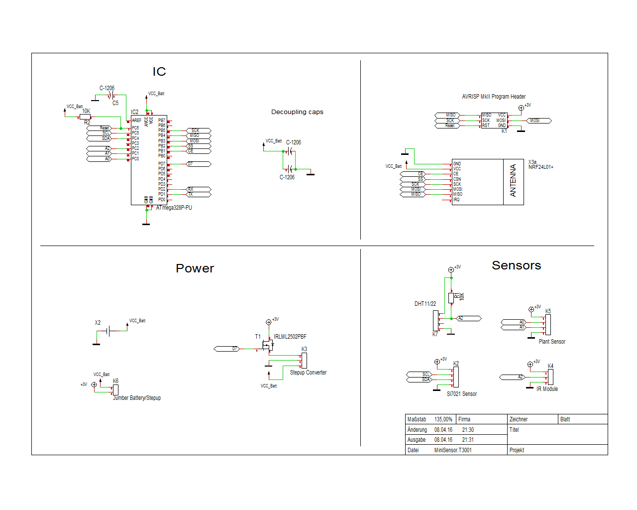
I also reworked my sensor board. My goal is a relatively small sensor running of a coin cell (small sensor is useless if the battery pack is double its size). I took some ideas from the excellent slim node but added/changed some parts.
The idea at the moment is to support DHT temp/hum sensors, Si7021 or similar I2C sensors, low power IR modules and moisture sensors. The moisture sensor pins should also be usable for (reed)switches.
Because some of these sensors require 3.3V (or even 5) I also added a boostconverter. If it's not needed there is a jumber to bridge it. I was worried about power consumption of the sensors when the IC sleeps so I also added a transistor to control the boost converter power.I am planning to use these small cases.
Do you guys see any errors? Does the transistor part work like that? Or do you have any suggestions what else to add?
Thanks for your feedback!PS I already added serial (RX/TX/GND/Battery) ouput pins and a pulldown resistor for the Gate of the transistor.
-
I just realized that I forgot to actually forgot to add the schematics... hard for you guys to help like that^^. So here they are, I hope you guys find some errors that I overlooked ;)
-
Any feedback? I will keep working on it for the next days. I am also thinking about adding some kind of light sensor. What is the cheapest one that works well with <=3.3V? What do you guys use?
-
I use an LDR
Hello! It looks like you're interested in this conversation, but you don't have an account yet.
Getting fed up of having to scroll through the same posts each visit? When you register for an account, you'll always come back to exactly where you were before, and choose to be notified of new replies (either via email, or push notification). You'll also be able to save bookmarks and upvote posts to show your appreciation to other community members.
With your input, this post could be even better 💗
Register Login