AC Routing Trace Width and Clearance
-
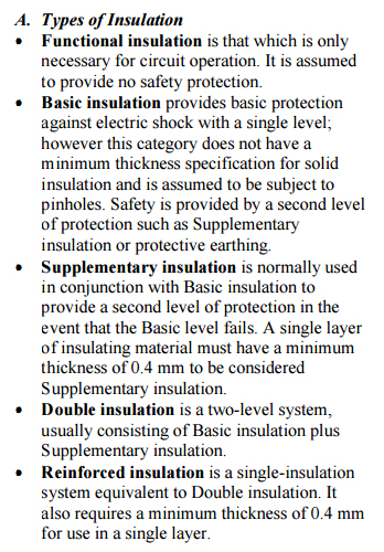
So from reading a provided link thanks to a previous post from @sundberg84, https://www.ieee.li/pdf/essay/safety_considerations_in_power_supply_design.pdf, it shows that we need to asses the amount of insulation needed to determine any advanced safety measures that need to be taken for AC power supply routing.
What level of insulation do we choose here, Functional, Basic/Supplementary, or Reinforced?
The way i have understood this information is that if a Power Supply board is going into an enclosure, does this mean that it only has to conform to the secondary insulation level, or have i misunderstood the type of insulation being discussed?
-
So from reading a provided link thanks to a previous post from @sundberg84, https://www.ieee.li/pdf/essay/safety_considerations_in_power_supply_design.pdf, it shows that we need to asses the amount of insulation needed to determine any advanced safety measures that need to be taken for AC power supply routing.
What level of insulation do we choose here, Functional, Basic/Supplementary, or Reinforced?
The way i have understood this information is that if a Power Supply board is going into an enclosure, does this mean that it only has to conform to the secondary insulation level, or have i misunderstood the type of insulation being discussed?
@Samuel235 I depends. Bare high voltage parts on PCB means no safety insulation. If inside it's inside a completely sealed (no connecting wires) enclosure, then the enclosure is the "supplementary" or "reinforced" type. Some PBC coating could probably provide the "basic" type.
If there are any wires going in or out through enclosure and/or connecting to PCB inside, then these must be considered in the "system". Typical a touchable USB connector in the wire end means the need for full safety insulation on your PCB between that conductor and high voltage conducting traces. Usually provided by transformers an safety (X or Y) capacitors and the creepage/clearance distances you got above. >3mm for 240Vac. -
@Samuel235 I depends. Bare high voltage parts on PCB means no safety insulation. If inside it's inside a completely sealed (no connecting wires) enclosure, then the enclosure is the "supplementary" or "reinforced" type. Some PBC coating could probably provide the "basic" type.
If there are any wires going in or out through enclosure and/or connecting to PCB inside, then these must be considered in the "system". Typical a touchable USB connector in the wire end means the need for full safety insulation on your PCB between that conductor and high voltage conducting traces. Usually provided by transformers an safety (X or Y) capacitors and the creepage/clearance distances you got above. >3mm for 240Vac.@m26872
So basically, if the container is not 100% sealed I need to have >3mm separation between the AC lines, is this what you're saying?
OR
Do i only need the >3mm between the AC line and the connection that is coming out of the module?I do plan on having some ventilation on my container and also there are 5 screw terminals on the board, one is the input AC, two are the relay output AC (x2) and then 2 more for external switches.
-
@m26872
So basically, if the container is not 100% sealed I need to have >3mm separation between the AC lines, is this what you're saying?
OR
Do i only need the >3mm between the AC line and the connection that is coming out of the module?I do plan on having some ventilation on my container and also there are 5 screw terminals on the board, one is the input AC, two are the relay output AC (x2) and then 2 more for external switches.
@Samuel235
Sorry, but "sealed" was not the best word. Of course IP-class affect your pollution level, but sure you can have a vented and still 'safe' enclosure.I think this document has been linked to before and has some info: https://www.ieee.li/pdf/essay/safety_considerations_in_power_supply_design.pdf
Important to understand the different aspects of safety (direct, indirect etc). It was several months since I read it, but I 'think' you should follow the creepage/clearance PCB design standards equally for line-2-line, line-2-earth (earthed user). For parts classification there're differences though (eg. X or Y cap).I'm no expert and I try to avoid guessing and don't have time to research more. Nor do I remember what I've learned. Perhaps someone else knows about this?
-
@m26872, that is the article that my image has been taken from ;)
I have read through that but again, i'm confused regarding the pollution and the separation needed for such designs. Its not making complete sense to me.
@Samuel235 haha, sorry about that.. embarrasing, now you see how focused I'm... :confounded:
-
@Samuel235 haha, sorry about that.. embarrasing, now you see how focused I'm... :confounded:
-
@m26872, don't be sorry, it shows that i'm at least looking through the correct documents haha.
@Samuel235 Why don't just accept the challenge and design with >3mm creepage?
-
I'm tempted to just do 3mm to be honest. But i would like to know the theory of why and how its worked out to be that. I'm also attempting to get it all located on a 50x50mm board along with the two relays, screw terminals for them and 2 switches too. Oh and all the DC circuitry too. So the smaller the creepage i'm allowed the more possible it would be. But i'm not attempting to sacrifice safety for size at all.
-
Does anyone have any opinions of voltages and current through screw terminals? I'm looking around for terminals for AC power, i can get some 3.5mm pitch that handle >250VAC and then other 3.5mm will only handle >100VAC. I know there is different grades of plastic and metal, but can there seriously be that much difference or is this an instance of the manufacturer just covering their backs and i would be fine to use any terminal?
Hello! It looks like you're interested in this conversation, but you don't have an account yet.
Getting fed up of having to scroll through the same posts each visit? When you register for an account, you'll always come back to exactly where you were before, and choose to be notified of new replies (either via email, or push notification). You'll also be able to save bookmarks and upvote posts to show your appreciation to other community members.
With your input, this post could be even better 💗
Register Login