Hardware design for 3.3V ProMini and 5v sensor

-
Hi all,
I'm trying to get a battery powered 3.3V MiniPro board working with a 5V JSN-SR04T Ultrasonic sensor, I'm using a DC-DC Step Up Boost Module 3v3 to power the ProMini and a 2N2222 transistor to switch on the DC-DC Step Up Boost Module 5V for the 5V JSN-SR04T, the 2N2222 switches with a 1K resistor on the base from PIN 5 on the ProMini. All this because the JSN-SR04T seems to stay on all the time, so to save some battery, I switch on the Step Up boost module, take the reading and switch it off again, but I'm getting strange readings, my questions
a ) Must there be a level convertor on the Echo and Trig pins, seeing the ProMini is 3.3V and the Ultrasonic is 5V
b ) I think it might be power related, as when I drive the Ultrasonic from an external supply, it seems to work ok, could it be that the 2N2222 is not powerful enough?
c ) The Boost module is off all the time, except when I take the readings and I switch it ON with GND, should I rather keep it on all the time and just switch the +5V line to the Ultrasonic sensor using the transistor when I take a reading?In the drawing below, 1B5 <> 4B5 is the Boost module
1B3 <> is the 3.3 Step up Boost module
and 1U- <> 4U is the Ultrasonic sensor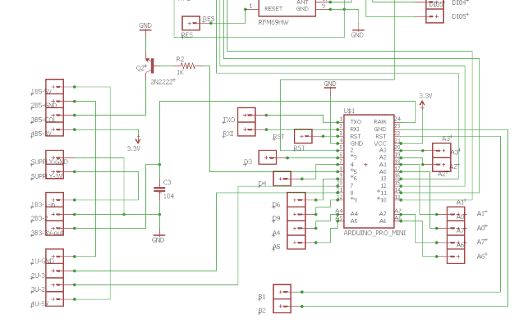
Any help / suggestions would be appropriated please
-
Hi all,
I'm trying to get a battery powered 3.3V MiniPro board working with a 5V JSN-SR04T Ultrasonic sensor, I'm using a DC-DC Step Up Boost Module 3v3 to power the ProMini and a 2N2222 transistor to switch on the DC-DC Step Up Boost Module 5V for the 5V JSN-SR04T, the 2N2222 switches with a 1K resistor on the base from PIN 5 on the ProMini. All this because the JSN-SR04T seems to stay on all the time, so to save some battery, I switch on the Step Up boost module, take the reading and switch it off again, but I'm getting strange readings, my questions
a ) Must there be a level convertor on the Echo and Trig pins, seeing the ProMini is 3.3V and the Ultrasonic is 5V
b ) I think it might be power related, as when I drive the Ultrasonic from an external supply, it seems to work ok, could it be that the 2N2222 is not powerful enough?
c ) The Boost module is off all the time, except when I take the readings and I switch it ON with GND, should I rather keep it on all the time and just switch the +5V line to the Ultrasonic sensor using the transistor when I take a reading?In the drawing below, 1B5 <> 4B5 is the Boost module
1B3 <> is the 3.3 Step up Boost module
and 1U- <> 4U is the Ultrasonic sensorAny help / suggestions would be appropriated please
@esawyja Search for comments on earth connected first. These modules seem to glitch if ground is switched, but I think a sacrificial ping command corrected it. Could be wrong but it stick in my head not to ground switch the US units....
-
mmmh can't seem to find anything on the switching of GND, anyone else, could you comment please
a ) Most likely no - but its quite easy to test using a simple voltage divider.
b ) You are probably right about the power - how about trying power it seperatly with a stable 5v (another source) and see if the strange values remain. Boost modules is the worst when it comes to noice and to be hones, Ultrasonic sensors are kind of sensitive! Are us using capacitors??
c ) Swithching the booster on and off will cause noice i think. Try the other option and see what happens but as said in B, theu are noicy and it might not be the cause. Are u using a cheap booster its ever worse.Sorry, im not an expert - just my thoughts.
-
mmmh can't seem to find anything on the switching of GND, anyone else, could you comment please
@esawyja If momory is still reliable it was on a thread specific to SRO4 but not sure whether here or elsewhere. As I said it is a recollection as I had considered using a sink transistor to ground for a 5v sensor on 3.3 node as you had but discarded the idea after reading this, hence my response. I ended up using a latching relay in my concept to completely disconnect +V and the minimal drain from any booster while retaining a solid ground... Trigger from 3.3 is not an issue for the unit I understood and @sunbergh84 is correctly stating the echo must be voltage divided to suit the 3.3v expected voltage at the pin. Surprised by his comment regarding noise from these converters, but had not considered it until now. OK, more digging :)
-
Hi all,
Thanks for the info, did some more testing last night, even when I power from an external source, still not getting correct values, tried it on 2 of the sensors. Also connected my meter to the 5v pins on the SR04T and I'm getting a solid 5V, I've added a delay to the transistor switch and measured for about 5 seconds and took a reading during that time and the 5V stayed solid, so I guess the only other thing is the level convertor, shall try that over the weekend and give some feedback. Thanks again for the advice and help -
Hi all,
Thanks for the info, did some more testing last night, even when I power from an external source, still not getting correct values, tried it on 2 of the sensors. Also connected my meter to the 5v pins on the SR04T and I'm getting a solid 5V, I've added a delay to the transistor switch and measured for about 5 seconds and took a reading during that time and the 5V stayed solid, so I guess the only other thing is the level convertor, shall try that over the weekend and give some feedback. Thanks again for the advice and help@esawyja - good work with excluding and narrowing down your problem!
-
Hi all
Hope this will be of help to someone, I did connect the level convertor, did not make any change to the incorrect values, but then I saw that some off my JSN-SR04T are marked JSN-SR04T-2.0.
Eventually figured out that the JSN-SR04T-2.0 does not work with my design, there are some reports of other people not getting them to work either, see
http://forum.arduino.cc/index.php?topic=474759.0 , but no resolve.
So the circuit design above seems to be fine, except that it does not work with the JSN-SR04T-2.0,
The only differences I can see are the following
JSN-SR04T-2.0 - Crystal at 8,000 and the chip marked 7B499, 8S003F3P6, PHL703
JSN-SR04T - Crystal at 11,0592 but no markings on the chips
See some comparison pictures below
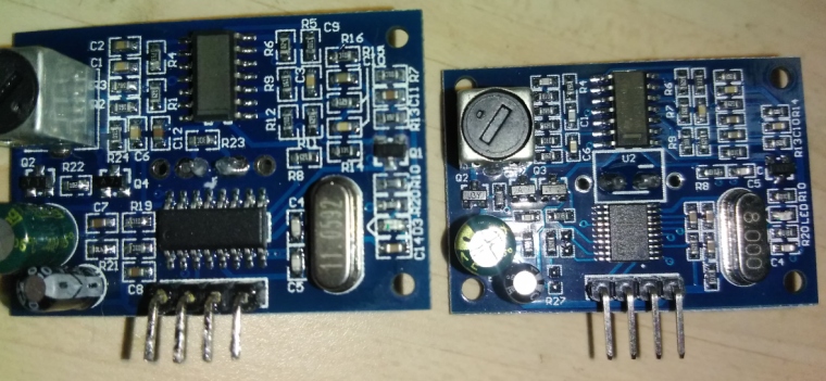
and the markings
-
Hi all
Hope this will be of help to someone, I did connect the level convertor, did not make any change to the incorrect values, but then I saw that some off my JSN-SR04T are marked JSN-SR04T-2.0.
Eventually figured out that the JSN-SR04T-2.0 does not work with my design, there are some reports of other people not getting them to work either, see
http://forum.arduino.cc/index.php?topic=474759.0 , but no resolve.
So the circuit design above seems to be fine, except that it does not work with the JSN-SR04T-2.0,
The only differences I can see are the following
JSN-SR04T-2.0 - Crystal at 8,000 and the chip marked 7B499, 8S003F3P6, PHL703
JSN-SR04T - Crystal at 11,0592 but no markings on the chips
See some comparison pictures below
and the markings
@esawyja My apologies if I am way off the beam here but I seem to recall something about two version of this, one where you measure the difference in time for the echo, the other which outputs a value on the echo pin according to the distance. Would this be the second type ?
-
@esawyja said in Hardware design for 3.3V ProMini and 5v sensor:
JSN-SR04T
Perhaps my memory is faulty, but I read somewhere of two types, and it was not a recent thread either. I was about to order some of these sensors, but will hold off doing so and watch for developments. Sorry, at least you have identified the problem, the question remains as to how the other version can be integrated.
-
Hi all
Hope this will be of help to someone, I did connect the level convertor, did not make any change to the incorrect values, but then I saw that some off my JSN-SR04T are marked JSN-SR04T-2.0.
Eventually figured out that the JSN-SR04T-2.0 does not work with my design, there are some reports of other people not getting them to work either, see
http://forum.arduino.cc/index.php?topic=474759.0 , but no resolve.
So the circuit design above seems to be fine, except that it does not work with the JSN-SR04T-2.0,
The only differences I can see are the following
JSN-SR04T-2.0 - Crystal at 8,000 and the chip marked 7B499, 8S003F3P6, PHL703
JSN-SR04T - Crystal at 11,0592 but no markings on the chips
See some comparison pictures below
and the markings
-
@esawyja in the top photo, what is the component in the top left hand side? Is it a variable resistor??
@Denverado I think it is for the beam width, not to sure, I've never adjusted them
-
This post is deleted!
-
@esawyja in the top photo, what is the component in the top left hand side? Is it a variable resistor??
@Denverado It is a variable inductor
-
Well it does make sense what you said, yes I'll be making sure that I order the correct one as well, very expensive exercise as I have 12 x JSN-SR04T-2.0 that I will not be able to use..
Thanks for all the help@esawyja FYI - As I posted on a separate thread, there was a comment against the type 2.0 on one supplier's site which read "Note: Version 2.0 requires echo pin to be pulled up to VCC. A 4.7K to 10K resistor can be used as pull-up resistor." I tried the 5v supply of the ultrasonic board, I tried Vcc from the Pro-mini and 3.3v from the board, I tried every delay, exhausted every variable possible as far as sketches went but still could not get this device to work..... Waiting on delivery of a DYP device to see if it resolves the problem, if it does, I will throw this particular board in file 13 and order another DYP....
-
@Denverado It is a variable inductor
-
@zboblamont Thanks! What is it used for on the sensor?
@Denverado If you mean the variable inductor, I don't know in this specific case...
They are normally used in conjunction with other components to adjust frequency to target, my guess would be to tweak the ultrasonic frequency to keep it within specification (40kHz?), but perhaps someone can advise who has investigated these devices in detail.
I would not advise tinkering with it unless you know the circuit and have the means to determine the effect. -
@Denverado If you mean the variable inductor, I don't know in this specific case...
They are normally used in conjunction with other components to adjust frequency to target, my guess would be to tweak the ultrasonic frequency to keep it within specification (40kHz?), but perhaps someone can advise who has investigated these devices in detail.
I would not advise tinkering with it unless you know the circuit and have the means to determine the effect.@zboblamont Thanks for the advice. I have been looking for a circuit diagram of the sensor to determine how adjusting it could change the beam. I would love if the beam was not as wide.
Hello! It looks like you're interested in this conversation, but you don't have an account yet.
Getting fed up of having to scroll through the same posts each visit? When you register for an account, you'll always come back to exactly where you were before, and choose to be notified of new replies (either via email, or push notification). You'll also be able to save bookmarks and upvote posts to show your appreciation to other community members.
With your input, this post could be even better 💗
Register Login