PCB verification request for latching valve controller
-
Hello everyone.
I’m an engineer and a farmer.
I’m working one a cheap solution for irrigation control valve.My specifications :
Use latching valve.
Long range remote control ( 500m with some tree)
4 month automy
Under 50 euro per unit
My complete design will be :
A remote center, based around an arduino pro mini with 4g module and an RF Module
This base will receive my order from my phone and send it to slave control valve using RF Module.I’m currently working on the PCB of the slave Valve.
But i need some help to check if the solution used is valid.
You will find all my work on git hub.To control a latching solenoid we need a circuit able to create a 100 ms 12v impulse through a 6 ohm solenoid.
On my schematic I create a step up module around a ADP1108.
I use a capacitor (C2) to store enough energy.
A Mosfet (controlled by an Arduino) and a 2 pole bistable relay are used to discharge this capacitor and switch the polarity if needed.!
I use an FS312 to secure my lipo battery.If the working principle is good I will calculate all the value of the components.
Do you see any problems on this PCB?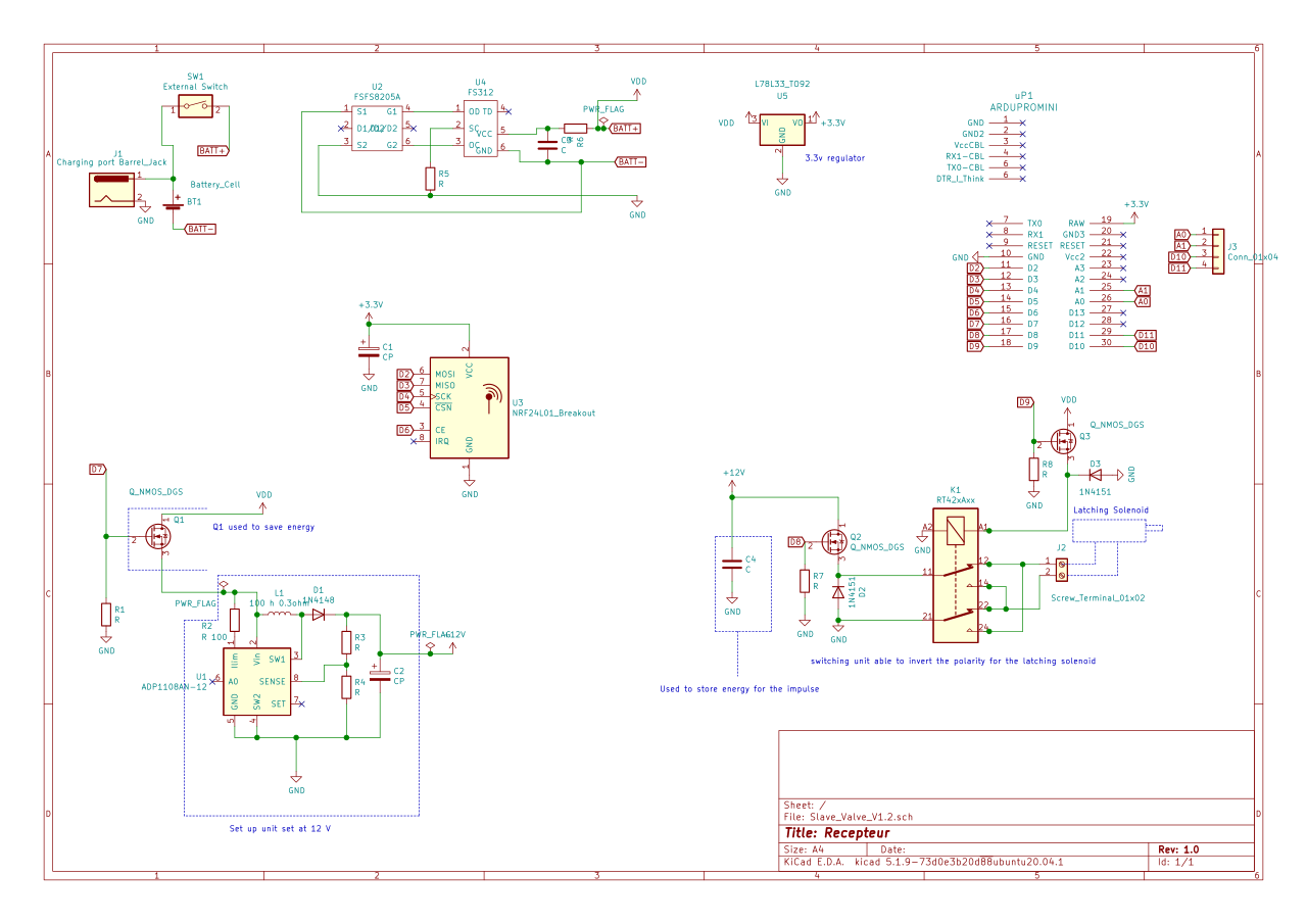
Thanks for your help.
Sorry for my rusty english. -
Hello everyone.
I’m an engineer and a farmer.
I’m working one a cheap solution for irrigation control valve.My specifications :
Use latching valve.
Long range remote control ( 500m with some tree)
4 month automy
Under 50 euro per unit
My complete design will be :
A remote center, based around an arduino pro mini with 4g module and an RF Module
This base will receive my order from my phone and send it to slave control valve using RF Module.I’m currently working on the PCB of the slave Valve.
But i need some help to check if the solution used is valid.
You will find all my work on git hub.To control a latching solenoid we need a circuit able to create a 100 ms 12v impulse through a 6 ohm solenoid.
On my schematic I create a step up module around a ADP1108.
I use a capacitor (C2) to store enough energy.
A Mosfet (controlled by an Arduino) and a 2 pole bistable relay are used to discharge this capacitor and switch the polarity if needed.!
I use an FS312 to secure my lipo battery.If the working principle is good I will calculate all the value of the components.
Do you see any problems on this PCB?
Thanks for your help.
Sorry for my rusty english.@wrendral
For the valve & driver I used a off-the-shelf battery-powered irrigation timer/valve (without the timer). Similar unit, US $24 here: and a $5.00 US TB6612FNG polarity-reversing motor drive board, all running from 9v battery.Original idea & code: here
Beware of possible failure mode if power fails while valve is open. ;-)
(Sorry I cannot help verifying your board, not an engineer, sometimes manage to get things to work anyway. )
-
I haven't checked it all out, but I do like that you have a diode on the relay coil to keep the voltage from spiking.
What voltage is VDD? Maybe it says somewhere, but if so I missed it.
But in general, it's better to have a combo of mosfets so that the relatively low voltage out of the Arduino can control the higher voltages safely.
The problem is that an N channel mosfet needs a positive voltage between the gate and the source. You've only got 3.3V available for the gate signal in your diagram, which means that best case you're going to have a threshold voltage difference. So the source voltage is down to say 2.8V. That's not going to do much for your solenoids.
You can rearrange the system and get rid of the relay so that you are only switching the low side of the solenoid and you have diodes for the high sides. (I haven't drawn it out, but I think it should be possible.)
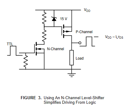
Alternatively, you can have N channel mosfets or NPN bipolar transistors controlling the gate of a P channel mosfet that does the actual high-side switching. Figure 3 of this doc shows the basic circuit for mosfets. If using an NPN in place of the N channel mosfet, it only requires small changes to the circuit. https://www.vishay.com/docs/70611/70611.pdf
-
Hello @wrendral. I have been operating a similar project for over a year now and experienced many issues. I operate about 20 custom made valves over a distance of 150 meters using NRF 2401L+, into an ethernet gateway. As @iguaan questioned do you intend to use PA/LNA module. My first advice would be to use a lower frequency radio. You will get it to work at 2.4GHz over that distance in open air but trees will definitely affect and even block the signal. How many valves do you intend to operate or is it just one? If more than one I would set up a repeater at the valve site which would talk to your base station and then you could use radios with PCB antennas on the valves. Be aware of the cheap omni antennas ( you should be using an omi or yagi antenna over that distance) as they vary depending on supplier. I have thrown out many after testing with an antenna analyser. (they caused various intermittent issues). What type of latching solenoid valve are you using? @Grubstake makes a good suggestion which I have also implemented, use a motor driver, it interfaces to the cpu and drives 12V. Also has protection. Switching 2A thru your solenoid may eventually burn out the relay contacts. @ejlane FYI, a latching solenoid needs reverse polarity switching to change states. Your suggestion is good but only switches on off. Also @wrendral is controlling a 12V step up inverter to supply the solenoid and save power by only turning it on via Q1 as required. Are you using J3. The radio is usually hooked up to D10,D11,D12,D13 to keep things standard and not use software emulated SPI interface. I would also wire up the radio IRQ even if you dont use it initially, if you are making a pcb. I assume your using 3.3V Pro mini therefore you can feed your 3.3V supply to VCC2 not Raw where it gets regulated again. Or feed VDD into raw. I would also put small electrolytics and .01uf caps close to the input and output of your regulator. It will work with out them but you may get intermittent issues when you start switching loads and running switching inverters. Just precautions for reliability! Your concept is ok. Good luck. I look forward to seeing how you go.
-
Oops, I missed the latching part somehow, even though it was stated multiple times. That would take a few more transistors. Though the way I would do it would be to just use an H-bridge motor controller chip/board. They would have everything you would need, as well as most having the free-wheeling diodes built in.
Hello! It looks like you're interested in this conversation, but you don't have an account yet.
Getting fed up of having to scroll through the same posts each visit? When you register for an account, you'll always come back to exactly where you were before, and choose to be notified of new replies (either via email, or push notification). You'll also be able to save bookmarks and upvote posts to show your appreciation to other community members.
With your input, this post could be even better 💗
Register Login