My Sensor node "motherboard" (MySensorsNode)
-
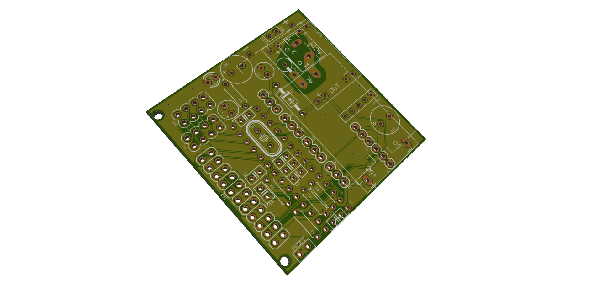
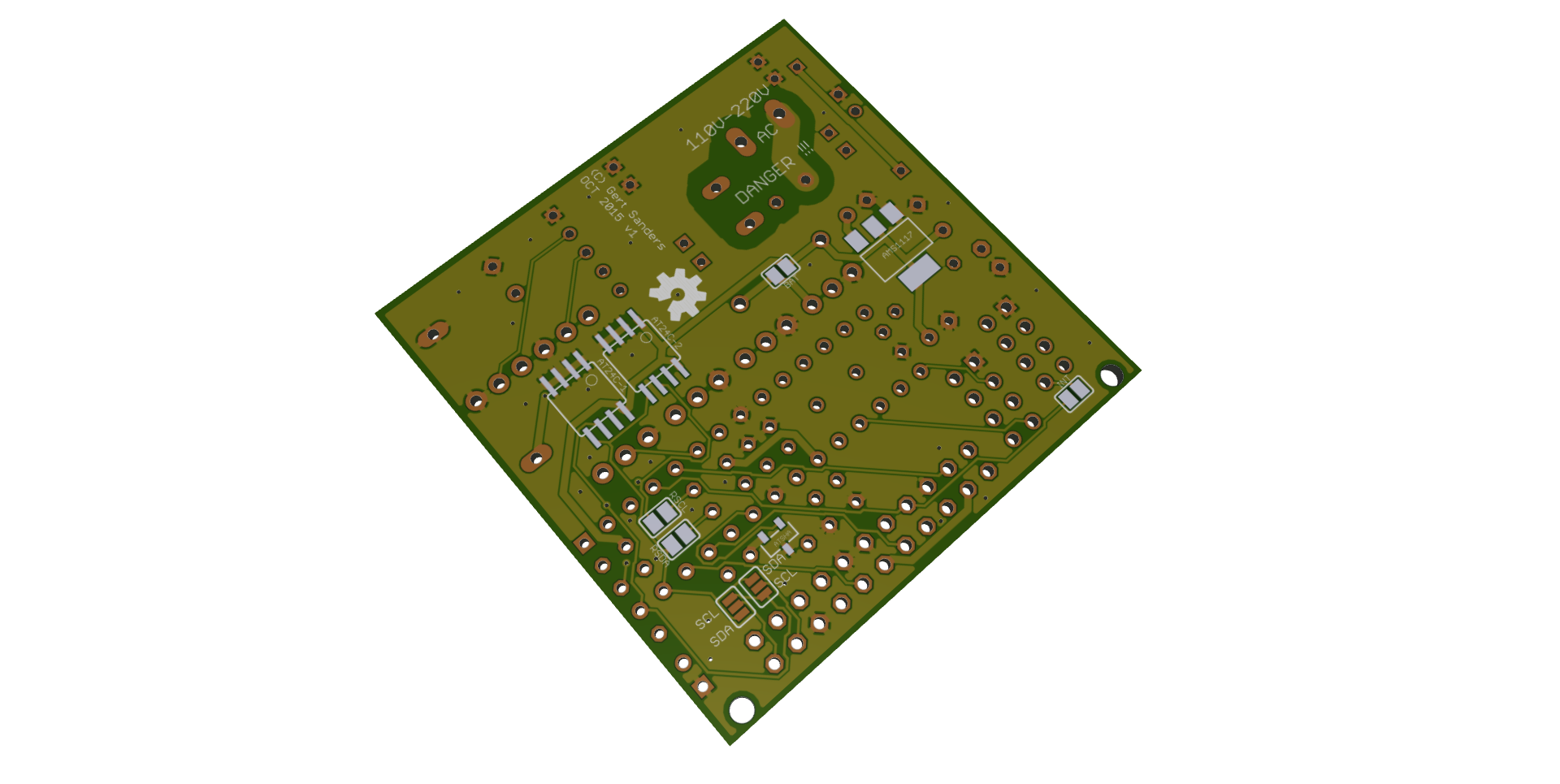
@Cliff-Karlsson : If the board below is tested (still on it's way from DirtyPCB to me), I will post the EAGLE files. This board allows several types of powering: battery (AAA), external battery (with DC regulator), direct 5V (if you mount the 3V3 LDO for the radio), HLK-PM01 for direct 120-220V AC. I need to test the various setups before I publish this, but a preview of the board is here:
-
@GertSanders said:
tested (still on it's way from DirtyPCB to me), I will post the EAGLE files. This board allows several types of powering: battery (AAA), external battery (with DC regulator), dir
Great, is it possible to use a RFM69? And do you solder an atmega (?) chip on to it or do you add a pro mini?
-
It's not designed for RFM69 but if you use an adapter and solder de bridge of the interrupt, then theoretically it could be used.
The processor is an atmega328p (not a pro mini). -
I just got my boards from dirtyPCBs but are there any list of the required components? And can I use rfm69 with a 5v pro mini or do I have to use a 3.3v pro mini?
-
I just got my boards from dirtyPCBs but are there any list of the required components? And can I use rfm69 with a 5v pro mini or do I have to use a 3.3v pro mini?
@Cliff-Karlsson you can find the BOM in GitHub under manufacturing. The board is designed for 3.3v pro mini. I have not taken 5v variant into consideration at all.
-
Are all components required? I know you can only use one radio / pcb and that the power sockets are optional. But I tried to find the cheapest components and after adding all the components from aliexpress the cost is almost 100 EUR and then I got probably atleast as many components from the more expensive shops left.
@Cliff-Karlsson well, I did not consider cost for my board. That said, 100EUR is definitely not required to spend for components on it. It depends on how you intend to use it and what flexibility you want. The ability to control certain aspects is optional as indicated by jumper configurations. I made it clear in my schematic what parts are optional to solder. You can of course cut more cost by skipping decoupling and such as well, but I can't vouch for board performance in that case.
-
@Anticimex Do you know what screws are expected for the BOX-2252? Is it M2 or something else?
-
@Anticimex Thanks!
-
Is it possible to only solder a mini pro 3.3v and an rfm69hw to your pcb and use it as a mysensors gateway? Or do I need to solder any more components?
-
Is it possible to only solder a mini pro 3.3v and an rfm69hw to your pcb and use it as a mysensors gateway? Or do I need to solder any more components?
@Cliff-Karlsson it was never design for that purpose, but I suppose you could. You'll need to see the schematics to determine what additional components are needed for power and regulation. Decoupling is also highly recommend. Remember that you need to expose a serial port for the GW.
-
@MiKa https://www.openhardware.io/view/2/MySensors-node
It's all there. However, be adviced that the board has a hard time fitting BOX-2252. -
Hi,
Which one is problem to fit into the box? 2252 or LE-BOX-0028 ?
Here You wrote about 2252 and on the openhardware site is LE-BOX-0028...
Regards,
MiKa -
I have not used dualoptiboot. But there should not be need for a special variant of it. It is a board that takes a standard arduino pro mini so a bootloader designed for that arduino should work just fine. Just make sure to configure the proper JEDEC ID for the flash.
-
I've took bootloader from: https://github.com/LowPowerLab/DualOptiboot
What JEDEC ID is correct for AT25DF512C?@bilbolodz that is stated in the datasheet of the device. Table 12.2. Manufacturer ID is 1Fh and Device ID part 1 is 65h. So you need to define MY_OTA_FLASH_JDECID to 0x1F65 (which is default I believe).
I don't know if you need to reconfigure DualOptiboot if you took it from LowPowerLab. Perhaps.