Rechargeable Lithium Ion Sensor Custom PCB
-
Makes sense. I am just comparing different editions, it appeared to me that the relay board could be a completelly separate project/pcb, as it would not work quite well on the rechargeable battery, and has quite a different purpose/audience I guess.
Rev 0.3 would then be trully "rechargeable" battery sensor (as in the title), and rev 1.0 would be completelly different, or does it contain same pins as 0.3 (pluss relay which can simply be ignored?).I would use it for motion, temp+hum, door switch and light/lux meter, is it then safe to order rev 1.0 for such a sensor?
And to order it, i usually/only need the .brd and sch files right?
p.s. custom housing looks very slick :)
C: OpenHAB2 with node-red on linux laptop
GW: Arduino Nano - W5100 Ethernet, Nrf24l01+ 2,4Ghz mqtt
GW: Arduino Mega, RFLink 433Mhz -
Makes sense. I am just comparing different editions, it appeared to me that the relay board could be a completelly separate project/pcb, as it would not work quite well on the rechargeable battery, and has quite a different purpose/audience I guess.
Rev 0.3 would then be trully "rechargeable" battery sensor (as in the title), and rev 1.0 would be completelly different, or does it contain same pins as 0.3 (pluss relay which can simply be ignored?).I would use it for motion, temp+hum, door switch and light/lux meter, is it then safe to order rev 1.0 for such a sensor?
And to order it, i usually/only need the .brd and sch files right?
p.s. custom housing looks very slick :)
@dakipro said:
Rev 0.3 would then be trully "rechargeable" battery sensor (as in the title), and rev 1.0 would be completelly different, or does it contain same pins as 0.3 (pluss relay which can simply be ignored?).
Rev 1.0 has nearly the same pins, except that you can only connect one switch (Rev 0.3: two switches) - but yes, you can simply ignore the relay, diode and transistor if you don't want to use a relay.
Nonetheless, if you are sure that you will never use the board with a relay, I suggest that you go with Rev. 0.3.And to order it, i usually/only need the .brd and sch files right?
It depends on the pcb manufacturer, but most of the time you will need the gerber files (which can be generated with the .sch file through the CAM-processor with the .cam file (which the specific board house provides).
PS: I ordered my boards from elecrow.
-
Thanks, I was ordering from oshpark before, but I see that elecrow has some nice prices as well.
I noticed that you have _gerber.zip for 1.0, if you by any chance find _gerber.zip for 0.3 I would appreciate if you upload it to the thread :)
(no, i am not lazy to convert them with eagle, but still not confortable and afreaid that I might select some wrong option :) )C: OpenHAB2 with node-red on linux laptop
GW: Arduino Nano - W5100 Ethernet, Nrf24l01+ 2,4Ghz mqtt
GW: Arduino Mega, RFLink 433Mhz -
Thanks, I was ordering from oshpark before, but I see that elecrow has some nice prices as well.
I noticed that you have _gerber.zip for 1.0, if you by any chance find _gerber.zip for 0.3 I would appreciate if you upload it to the thread :)
(no, i am not lazy to convert them with eagle, but still not confortable and afreaid that I might select some wrong option :) )@dakipro here you go:
0_1470866547655_Gerber_rev0.3.zip
Be aware that this are the gerber files for the pcb service from elecrow. Other pcb services may have other specifications!
-
Hi HenryWhite,
Great job, very nice.
I have some questions:
- Why do you sent input voltage to A0? is it for voltage supervision?
- Is it possible to have your sketch file?
Thanks for your sharing,
TouFou@toufou said:
Hi HenryWhite,
Great job, very nice.
I have some questions:
- Why do you sent input voltage to A0? is it for voltage supervision?
- Is it possible to have your sketch file?
Thanks for your sharing,
TouFouHi, yes it's for measuring the battery level.
You can find the schematics and all the other files in my first post. -
Hi,
Thanks for your reply.
In the first post, i see schematics, brd and gerber file, but i don't see .ino file to flash arduino pro mini.....@toufou said:
Hi,
Thanks for your reply.
In the first post, i see schematics, brd and gerber file, but i don't see .ino file to flash arduino pro mini.....You can adapt the example sketches MySensors offers, it shouldn't be hard. Also the sketch will depend on what you plan to use the board for. (Motion, Switch, Temperature,...)
-
Ok!
I thought you had specific because your sensor is about 10month with arduino regulator! excellent.
Another question:
You use a motion sensor as i want. You make a reference to a hack to use it with 3.3V instead of 5V. Have you a link to see that?Thanks
-
Ok!
I thought you had specific because your sensor is about 10month with arduino regulator! excellent.
Another question:
You use a motion sensor as i want. You make a reference to a hack to use it with 3.3V instead of 5V. Have you a link to see that?Thanks
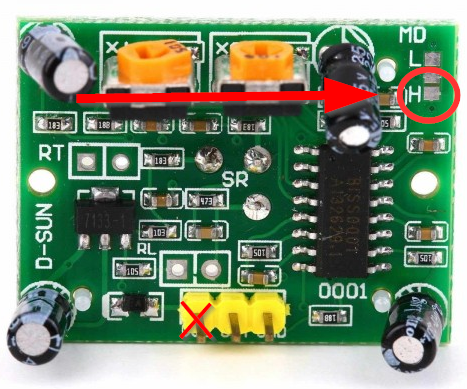
@toufou said:
You use a motion sensor as i want. You make a reference to a hack to use it with 3.3V instead of 5V. Have you a link to see that?
Yes, here's a picture (the only thing you have to do is solder vcc to the HIGH-pad of your motion sensor):