Figaro TGS5042 Carbon Monoxide Sensor & Op Amp
-
I'm currently trying to set a circuit up for a Figary TGS5042 Carbon Monoxide sensor using an Op Amp in a non-inverting configuration but having no luck what so ever, i think anyway.
I have configured my circuitry in two seperate ways trying to figure this out. I have recently found a little 'review/guide' blog post which i've read through with no joy either, here. This is my Op Amp datasheet. Am i correct in expecting to receive 0v on the output pin when there is nothing detected, just like the video in the linked blog post shows?
So, the first circuit i tried is that specified by the datasheet;
 .
.All i'm getting here is a voltage readout on the output pin in relation to gnd is 4.35v with no movement what so ever.
So i then go on to consider his own circuit of;

Still nothing. And more specifically, i get the same reading of 4.35v.
At this point i'm starting to think that either i have done something in correct in terms of wiring. Am i even measuring it correctly? Multimeter COM lead on gnd, and the Vma lead on the output pin. I do know that if the sensor is not connected to anything it should be shorted out, and more specifically it should be shorted out for transport, as the datasheet reads "When the sensor is shipped, the working electrode and counter electrode are connected (i.e. short circuited) by mounting on conductive mat (-A00) or a metal ribbon (-B00) in order to avoid polarization of the electrodes." Now, this is all that it was shipped in, does this count as the conductive mat and therefor could it be that the sensor is actually faulty?
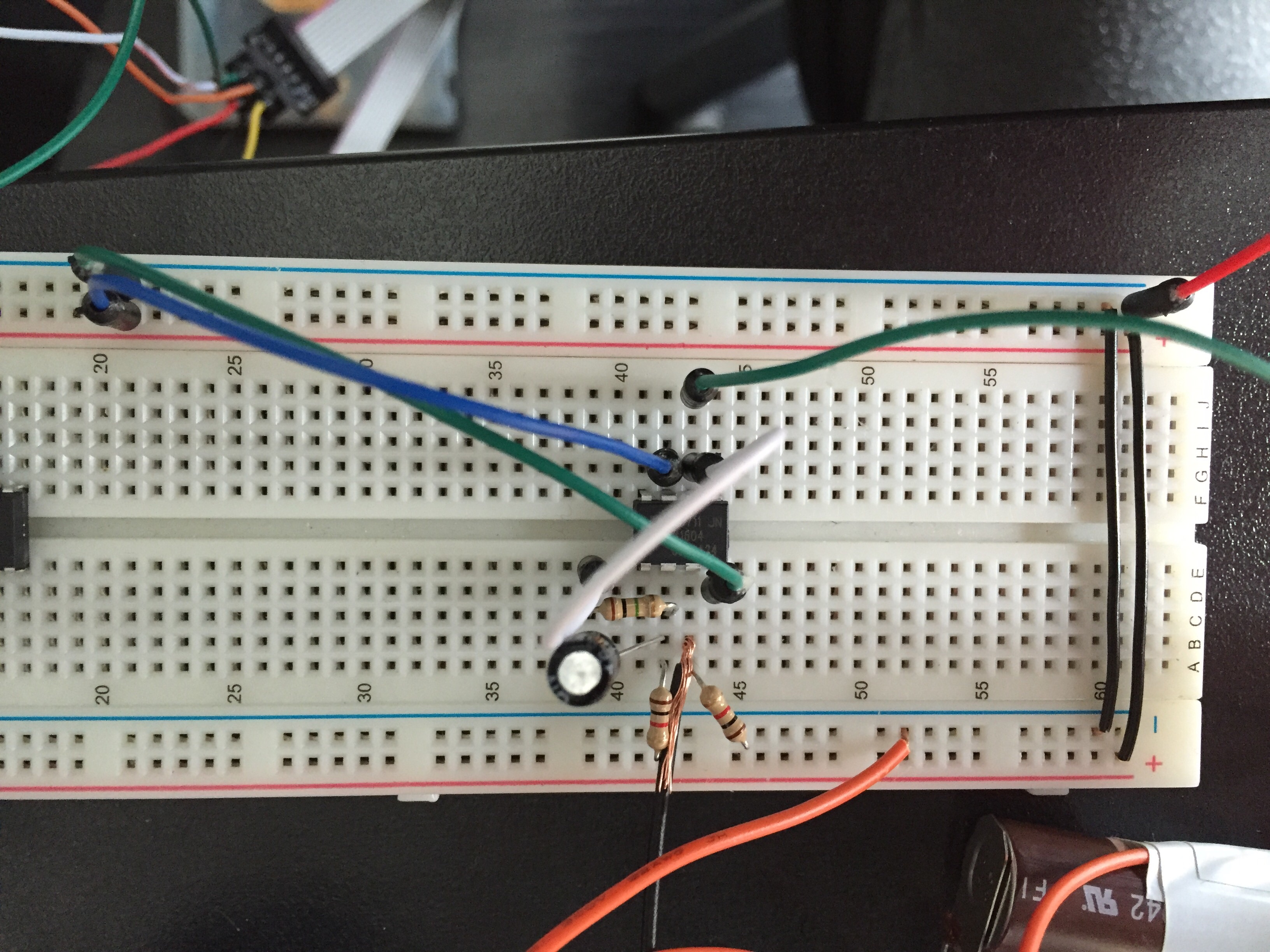
Here is my breadboard image, if you can workout what goes where, please ask questions if more information is needed....
-
The second circuitry with the fixed load resistor is giving me some hope with this sensor, i'm able to get a very small movement on the current of the sensor over the fixed load resistor. So i think it is safe to assume that the sensor is in working order and therefor something that i am doing in correctly to get the OP AMP solution working. Does anyone have any OP AMP experience to shine any light onto my issues here?
-
I'm currently trying to set a circuit up for a Figary TGS5042 Carbon Monoxide sensor using an Op Amp in a non-inverting configuration but having no luck what so ever, i think anyway.
I have configured my circuitry in two seperate ways trying to figure this out. I have recently found a little 'review/guide' blog post which i've read through with no joy either, here. This is my Op Amp datasheet. Am i correct in expecting to receive 0v on the output pin when there is nothing detected, just like the video in the linked blog post shows?
So, the first circuit i tried is that specified by the datasheet;
.All i'm getting here is a voltage readout on the output pin in relation to gnd is 4.35v with no movement what so ever.
So i then go on to consider his own circuit of;
Still nothing. And more specifically, i get the same reading of 4.35v.
At this point i'm starting to think that either i have done something in correct in terms of wiring. Am i even measuring it correctly? Multimeter COM lead on gnd, and the Vma lead on the output pin. I do know that if the sensor is not connected to anything it should be shorted out, and more specifically it should be shorted out for transport, as the datasheet reads "When the sensor is shipped, the working electrode and counter electrode are connected (i.e. short circuited) by mounting on conductive mat (-A00) or a metal ribbon (-B00) in order to avoid polarization of the electrodes." Now, this is all that it was shipped in, does this count as the conductive mat and therefor could it be that the sensor is actually faulty?
Here is my breadboard image, if you can workout what goes where, please ask questions if more information is needed....
@Samuel235 said:
...does this count as the conductive mat
Conductive foam is impregnated with carbon and is generally black in color and denser than styrofoam. The pink foam common in packaging is 'anti-static' but not conductive. Methinks that is simple packaging styrofoam. As a side note, conductive foam is very useful for making pressure sensors, never throw it away.
-
I can confirm the sensor is working by using the basic measurement circuit.
So this circuit is simply a 1k resistor connecting the two terminals of the sensor together with the 'counter' terminal also connected to GND. With this circuit i have sensed the following voltages;
1K resistor - 5 minute settling time - 0.3mV
1K resistor - 2 minutes 30 seconds exposed to burning paper - 1.5mVBy doing this basic test we can assume that the sensor is working now. However what i'm still struggling to get to work it integrating it with a OP AMP, these are the steps i have taken to get from this basic circuit to the OP AMP attempt.
- I have left the 1k Resistor in to enable the sensor to stay safe as instructed by the datasheet to not allow the terminals to get polarized.
- Switched the sensor orientation around.
- Connected counter terminal to the non-inverting supply (- pin on op amp)
- Connected working terminal to the inverting supply (+ pin on op amp)
- Connected supply voltage (5V) to the V+ pin on op amp.
- Connected V- and inverting pin on op amp to GND.
- Connected op amp output pin back to the non-inverting input with a feedback resistor of 5.6K resistor and 1uF cap.
So the entire circuit looks like;

However, the multimeter in this simulation is showing 2.47V where in the exact setup to compare the simulation to my circuit i get 4.2V without the sensor attached.
I do suspect this to be an incorrect op amp selection as the app note for the figaro sensor does specify a rail to rail op amp, however the op amp they show doesn't state it is a rail to rail device.
Would the slew rate of the op amp have any effect on this?
I also am very aware, although not sure how to calculate exact figures, that with this op amp not being a rail to rail device it will not allow the output voltage to go close to V- or V+ (GND or 5V in this case).
-
I since purchased some TLC272CP OP AMPS and with the basic measurement circuit, specified by the datasheet of the Figaro Sensor, i can confirm this sensor is working perfectly!
-
I since purchased some TLC272CP OP AMPS and with the basic measurement circuit, specified by the datasheet of the Figaro Sensor, i can confirm this sensor is working perfectly!
@Samuel235 Nice with the same circuit right??
which is in 2nd pic?
Hello! It looks like you're interested in this conversation, but you don't have an account yet.
Getting fed up of having to scroll through the same posts each visit? When you register for an account, you'll always come back to exactly where you were before, and choose to be notified of new replies (either via email, or push notification). You'll also be able to save bookmarks and upvote posts to show your appreciation to other community members.
With your input, this post could be even better 💗
Register Login