Ceech board upgrade
-
The board will receive a new design with TP4056 battery charger.
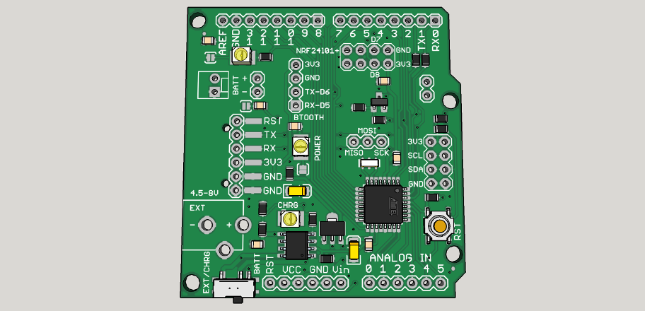
Charge current and battery voltage will be reported on ADC6 and ADC7.
Mosfet will be available for external load regulation. It is connected to D3.
There are three sockets for:
bluetooth
NRF24l01+ and
I2C modules. -
Are we able to use the Rfm69 module with nrf24l01 adapter? Is the IRQ PIN connected to D2?
-
Are we able to use the Rfm69 module with nrf24l01 adapter? Is the IRQ PIN connected to D2?
@kenci It can be used with Rfm69. And yes, IRQ pin is connected to D2.
-
New boards are ready and are being tested. Here is one connected to a Bluetooth module charging a battery:
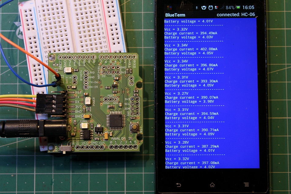
This is the code used in battery voltage and charge current monitoring:
float readVcc()
{
  signed long resultVcc;
  float resultVccFloat;
  // Read 1.1V reference against AVcc
  ADMUX = _BV(REFS0) | _BV(MUX3) | _BV(MUX2) | _BV(MUX1);
  delay(10);                           // Wait for Vref to settle
  ADCSRA |= _BV(ADSC);                 // Convert
  while (bit_is_set(ADCSRA,ADSC));
  resultVcc = ADCL;
  resultVcc |= ADCH<<8;
  resultVcc = 1126400L / resultVcc;    // Back-calculate AVcc in mV
  resultVccFloat = (float) resultVcc / 1000.0; // Convert to Float

  return resultVccFloat;
}

const int current = A6;
const int lipo = A7;


float vout = 0.0;
float vin = 0.0;
int value = 0;

void setup()
{
  Serial.begin(9600);
}

void loop()
{
  float napetost = readVcc();

  float tok = ((analogRead(current) * napetost / 1024 ) * 1200) / 3; // convert the ADC value of charge current to miliamps
  float baterija = ( analogRead(lipo) * napetost / 1024 ) * 2; // measuring battery voltage

  Serial.print("Vcc = ");
  Serial.print(napetost);
  Serial.println("V");
  delay(400);
  Serial.print("Charge current = ");
  Serial.print(tok);
  Serial.println("mA");
  delay(400);
  Serial.print("Battery voltage = ");
  Serial.print(baterija);
  Serial.println("V");
  delay(400);
  Serial.println("----------------------------");
  delay(2000);
}
/*
Improving accuracy:
To do so, simply measure your Vcc with a voltmeter and with our readVcc() function. Then, replace the constant 1107035L with a new constant:
scale_constant = internal1.1Ref * 1024 * 1000
where
internal1.1Ref = 1,1 * Vcc1 (per voltmeter) / Vcc2 (per readVcc() function)
Example:
For instance, I measure 3,43V from my FTDI, the calculated value of Vref is 1,081V.
So (1,081 x 1000 x 1024) = 1107034,95 or 1107035L rounded up.

Use smoothing example from IDE to smooth the data from ADC.
*/
Charge current is limited to 400mA and can be easily changed to another value by changing just one resistor.
Hello! It looks like you're interested in this conversation, but you don't have an account yet.
Getting fed up of having to scroll through the same posts each visit? When you register for an account, you'll always come back to exactly where you were before, and choose to be notified of new replies (either via email, or push notification). You'll also be able to save bookmarks and upvote posts to show your appreciation to other community members.
With your input, this post could be even better 💗
Register Login