ESP8266 - 07: What are the correct connections for deepsleep? (SOLVED)
-
This is mostly an ESP8266 related question. However, since my goal is to adapt this sensor for uses with the MySensors library I thought I could try finding some support here also.
Long story short, I am building an ESP8266 based mailbox sensor, loosely following the post found here. The concept idea is to have the MCU in deep sleep forever until it is reset by the reed switch. Then the MCU wakes up, connects to the Internet and sends a message.
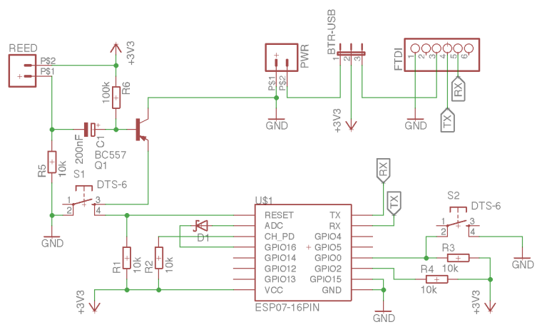
Above you can see my circuit schematic. Based on my previous ESP8266-01 experience I have:
- VCC and CH_PD pulled up with 4k6 or 10k resistors
- GPIO0 and GPIO2 pulled up with 4k6 or 10k resistors
- tact buttons in order to be able to flash the mcu with the same board
- GPIO16 connected to RST in order to wakeup from deep sleep.
I realized that it is impossible to wake from ESP.deepSleep(0) using the magnetic reed switch, except if I disconnect GPIO16 from RST. I suppose that the GPIO LOW is not low enough to reset the mcu, because RST is pulled up to VCC. Correct?
Of course after disconnecting GPIO16 from RST, it is not possible any more to wake up from a predefined period deep sleep (in case that this is needed), e.g. ESP.deepSleep(1000).
So I am wondering... Is it necessary for ESP8266-07 (or 12) to connect GPIO16 to RST (like we do for esp-01) in order to be able to use the deep sleep function for a predefined time period? Could someone propose how the ESP07 should be connected correctly? There is a lot of contradicting info on the Internet.
*SOLUTION: The trick is to add a (schottky) diode between the RST and GPIO16 (see updated circuit). With this configuration it is possible to wake up the mcu from esp.deepsleep(0) by either pressing the tact button or by opening the magnetic switch. It is also possible to wake up from predefined sleep time esp.deepsleep(time). The 470 Ohm (or 1K) resistor also works, but it depends on the neighboring component values. The diode is more well defined.
Hello! It looks like you're interested in this conversation, but you don't have an account yet.
Getting fed up of having to scroll through the same posts each visit? When you register for an account, you'll always come back to exactly where you were before, and choose to be notified of new replies (either via email, or push notification). You'll also be able to save bookmarks and upvote posts to show your appreciation to other community members.
With your input, this post could be even better 💗
Register Login