[contest] My 12 input high precision pulse counter (kWh/ W)
-
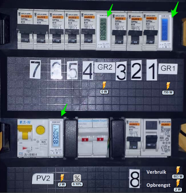
For my meter cupboard I have installed simple digital meters with S0 output.. With the help of some creative public domain resources I managed to make a power metering system with accurate momentary power consumption and usage monitoring (here with Domoticz as controller).
-
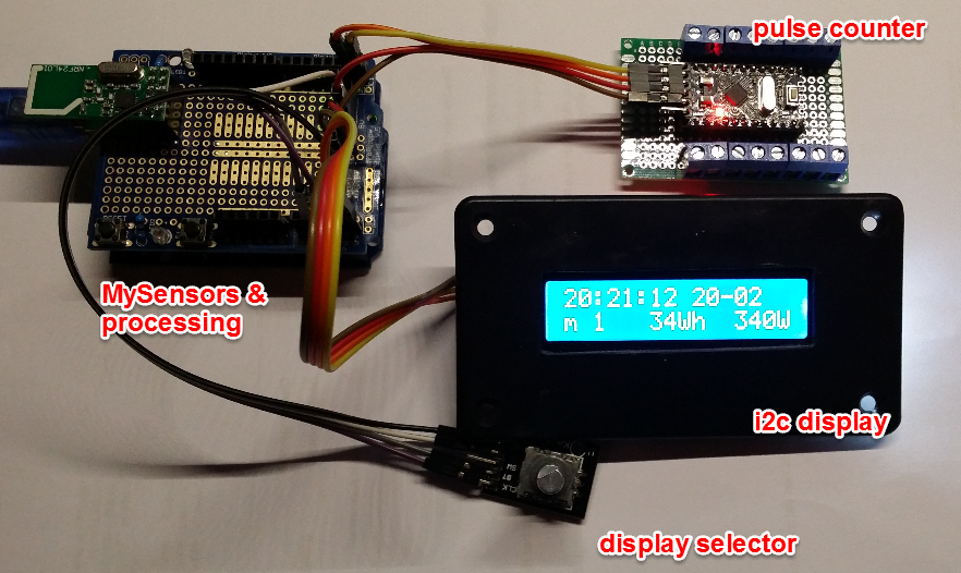
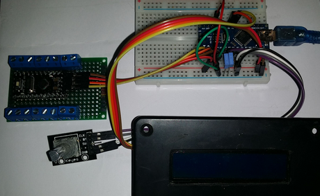
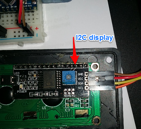
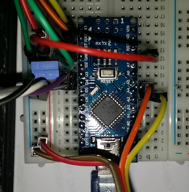
the project consists of two arduino's linked through serial. The first one is the high speed 12 input measuring device attached to the S0 meters (6 operational in my case). I have slightly changed the design of this Open Energy Project to spit out JSON records. Into a second Arduino which is responsible for connecting to the MySensors network/ converting units and addressing a local (I2C) 2x16 display of the meter readings. Below the prototype.. (the real thing is in production and hidden in the cupboard ;), except the display )
-
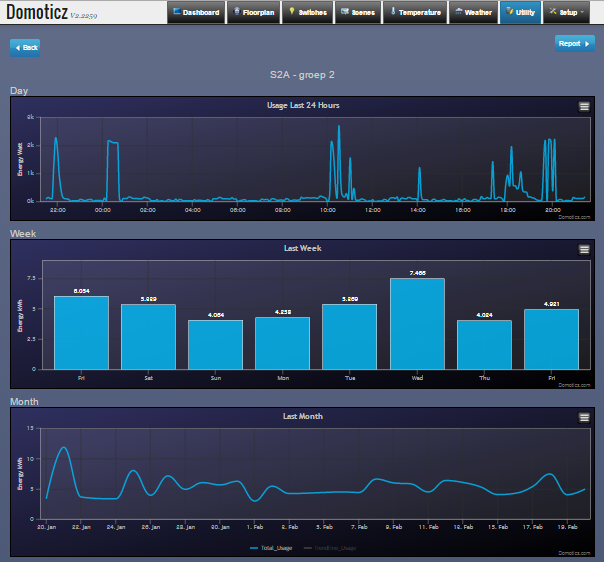
A few more pictures: Domoticz graphing for one of the meters. (good thing I can compensate with Solar)
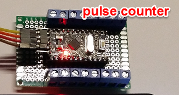
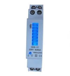
Pulse meter used (€ 22 a piece). Take care, not a real hobby article to connect...
@AWI Are those KWH DIN meters from Ebay or did you buy them locally? I was thinking of doing something similar a while back but was put off by the cost and inability to install them myself (not understanding much of mains installation and phases). Would be great to single out the heating system at least so I can have two groups. Not easy to make any serious graphs when the pump is pulling ~3kW once or twice an hour.
-
@AWI Are those KWH DIN meters from Ebay or did you buy them locally? I was thinking of doing something similar a while back but was put off by the cost and inability to install them myself (not understanding much of mains installation and phases). Would be great to single out the heating system at least so I can have two groups. Not easy to make any serious graphs when the pump is pulling ~3kW once or twice an hour.
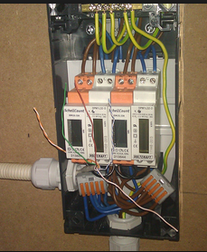
@bjornhallberg I bought them locally but these things are available everywhere. Not difficult to install when you have a single phase mains. You can also put them in a separate box (piicture from the public domain.....). .
After that you can play with a reliable "once per Wh" pulse..
-
The pulse counter and code
The pulse counter produces a simple JSON string per S0 meter every 10 seconds. The string shows the meter number. Number of counts (Wh ) since last send. Average period (duty cycle in ms) between pulses to calculate the current power (3,600,000,000/ period) and a pulse accumulation since the start of the counter. You can use this to keep things in sync when the serial connection or processing is not always stable.
https://codebender.cc/sketch:86789
for the sake of Codebender I have combined all in one file.
The pulse counter can be attached to any serial port (using a UNO, Nano or FTDI) and used for all kinds applications and counting purposes. I will focus on MySensors...
-
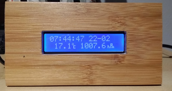
The main unit in production. I used a Nano or UNO for easy debugging/ programming and 5v USB charger. The rest is deep down in the closet in a 1 Euro housing (no need for fancy 3d printing). The display is fitted in bamboo left overs from IKEA boxes.
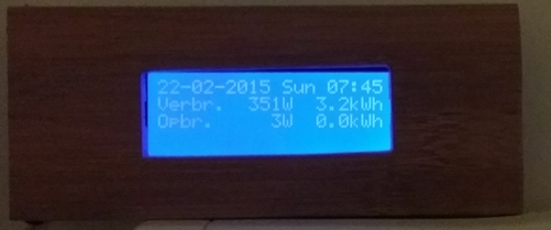
(it displays time/ pressure from a left over BMP180 now)Another one with a 4x20 display, with room for some extra information
And the code.
https://codebender.cc/sketch:87047 -
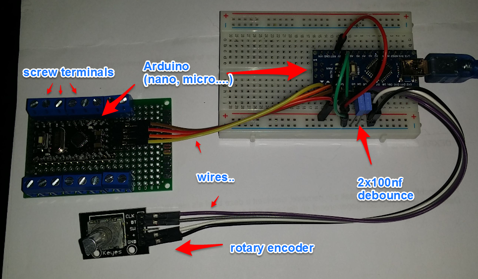
Parts list & build instruction (excluding radio...)
Price (estimate):
2 x arduino (ali): Euro 5
1 x I2C LCD (ali): ,, 4
1 x rotary encoder ,, 2
2 x 100nf ,, 0.4
16 x screw terminals ,, 1.6
wires ,, 1
breadboard/ pcb ,, 2Total Euro 16
The S0 meters will cost your more: Euro 12-30 / pcs, including (backlight) display, excluding installation.
(eg. SDM120.pdf there are also types available which give you a MODBUS RS-485 interface and kWh, V, A, PF, F, kWh-r for around Euro 50/pcs) -
This is great , exactly what i was looking for.
I do have a few questions, is it possible to double the amount of inputs ?
I "need" 24 or 25 inputs since i got so many meters like on the picture.
Or is it possible to build 2 of these devices and that domoticz detect it ?Also, can you maybe tell me if it is possible to keep a log from all the sensors apart from each other ?
So you can check what meter 1 has used for the amount of days/weeks/years ?
Or it it all combined to 1 number ? -
This is great , exactly what i was looking for.
I do have a few questions, is it possible to double the amount of inputs ?
I "need" 24 or 25 inputs since i got so many meters like on the picture.
Or is it possible to build 2 of these devices and that domoticz detect it ?Also, can you maybe tell me if it is possible to keep a log from all the sensors apart from each other ?
So you can check what meter 1 has used for the amount of days/weeks/years ?
Or it it all combined to 1 number ?@Vince Glad you like it. It is possible to extend the number of inputs but I would suggest to add another arduino for that purpose. The whole thing is timing critical. Especially in relation to "counting" the actual power. Every counter is logged separate and sent to the gateway controller.
-
Great project, ive made this project, i had to declare the chars this was not done in your script? i had to declare:
lcd.createChar(1, degCelcius);
lcd.createChar(2, hecto);
lcd.createChar(3, Pascal);
lcd.createChar(4, Lux);
lcd.createChar(5, visible);
lcd.createChar(6, infrared);
lcd.createChar(7, rel_humidity);i declared them for eg:
uint8_t degCelcius[8] = {0x18,0x18,0x3,0x4,0x4,0x4,0x3};i had to change the display adress to 0x3F and tested this with a script to verify and this works, display SCL is connected to pin A5 and SDA is connected to A4.
ive compiled it without errors and uploaded the sketsh to the arduino nano, when connecting the slave arduino (pro mini) board the Rx led will blink every 10seconds when the json data is received.
but the display stays like this:
http://forum.arduino.cc/index.php?action=dlattach;topic=157817.0;attach=40625
on the top row only blocks are visible, any idea why? -
Great project, ive made this project, i had to declare the chars this was not done in your script? i had to declare:
lcd.createChar(1, degCelcius);
lcd.createChar(2, hecto);
lcd.createChar(3, Pascal);
lcd.createChar(4, Lux);
lcd.createChar(5, visible);
lcd.createChar(6, infrared);
lcd.createChar(7, rel_humidity);i declared them for eg:
uint8_t degCelcius[8] = {0x18,0x18,0x3,0x4,0x4,0x4,0x3};i had to change the display adress to 0x3F and tested this with a script to verify and this works, display SCL is connected to pin A5 and SDA is connected to A4.
ive compiled it without errors and uploaded the sketsh to the arduino nano, when connecting the slave arduino (pro mini) board the Rx led will blink every 10seconds when the json data is received.
but the display stays like this:
http://forum.arduino.cc/index.php?action=dlattach;topic=157817.0;attach=40625
on the top row only blocks are visible, any idea why?@RCF It was a long time ago.... can't remember the details. It could be that the display library does not work for your LCD. If I can find a minute I will review the sketch.
-
I have the same display as in your post > see the first display on this page: http://arduino-info.wikispaces.com/LCD-Blue-I2C#v1
there is also a test script which works fine on adress 0x3F, but i did already change that adres in your script but the display shows blocks on the first line. the library is the same i believe.
it would be grat if you could help :).by the way if i connect a RF module will the data sended be compatible with http://openenergymonitor.org/emon/guide the Emonbase unit?
-
Could you explain how to connect the sensors 2 pins?
On http://openenergymonitor.org/emon/buildingblocks/12-input-pulse-counting they connect it like in the picture?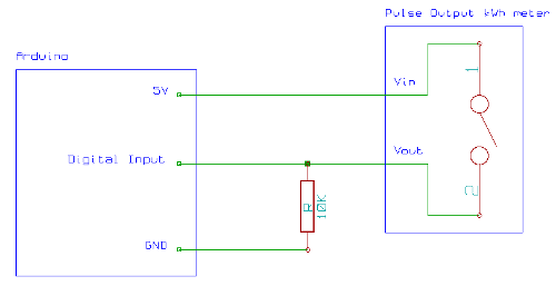
Is it by this also like that?? Because i can't see the pull down resistors on yours..
-
You noticed it right. I used the internal pull-up of the Arduino. Gnd is directly connected and input with the internal pull-up to vcc.
-
So i don't need the extra pulldown resistor and could connect everything like drawn down below?
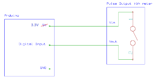
With the differance that i'm using a arduino mini wich runs on 3.3V and doesn't have a 5V point...
-
Updated the master sketch... you need the load the latest libraries mentioned in the heading..(RotaryEncoder & arduinoJson). Adapt your settings to your display if needed (I2C address, etc.).
The sketch depends on a "read/ get" from the controller for the last (or user filled) kWh values. Many controllers are lacking this functionality (i.e. Domoticz). I have a version without this (useful ) syncing capability under construction. This will allow local changes in the history by means of the rotary encoder./*----------------------------------------------------------------------* * MySensors interface to AWI 12 input usage/ power Meter * * meter generates Power/ Usage/ Cumm. usage for 12 independent chann. * * 16x2 (I2C) Display shows consumption * * * *----------------------------------------------------------------------*/ /* // // Licence: GNU GPL // // Author: AWI 2015 // Updates: AWI 20150815, new RotaryEncoder & ArduinoJson libraries // // // continuously: // 1. read JSON strings from Pulse12Counter slave , format {"m":meter,"c":count,"r":rate, "cA":countAccum} // 2. calculate real time Power from "rate" // 3. store values // 4. send to controller // Get consistency with controller - controller should only be updated when initial values have been received: // 1. read Wh values from controller (local last values should be in sync with controller) // 2. compare with stored readings. Action accordingly: // - if controller Wh > stored last reading: new startup from counter, send new Wh increment and adjust readings. // - if controller Wh < stored last reading: something went wrong with last update, send updated values from counter // // Other: // 1. display on local LCD, time & energy values, usage can be shown as Daily & Total // 2. rotary encoder to browse the different displays // // Caution: pulse meter is connected to std serial (pin D0), Serial.print can still be used // Disconnect pulse meter when programming via FTDI! (sync error) */ #include <MySensor.h> // MySensors network #include <SPI.h> #include <LiquidCrystal_I2C.h> // display I2C #include <Time.h> #include <Wire.h> #include <RotaryEncoder.h> // RotaryEncoder to browse displays https://github.com/mathertel/RotaryEncoder #include <ArduinoJson.h> // used to parse the simple JSON output of the pulse meter https://github.com/bblanchon/ArduinoJson // Constants #define NO_METERS 5 // number of meters used (max 12) #define NODE_ID 11 // fixed MySensors node ID #define ENCODER_PINA 3 // RotaryEncoder pins #define ENCODER_PINB 4 // *** Global variables // stores LCD text //char lastLCD1[21] = "Line1 - first "; //char lastLCD2[21] = "Line2 - second "; class pulseMeter // meter class, store all relevant data (equivalent to struct) { public: unsigned long UsageWh; // last (current) usage (in W) from pulse counter unsigned long UsageAccumWh; // usage accumulator (to keep in sync) from pulse counter unsigned long PowerW; // actual power, calculated from pulse "rate" unsigned long DayUsageWh; // daily usage for display bool Updated ; // flag to check if update from controller is received }; pulseMeter pulseMeters[NO_METERS] ; // define power meters RotaryEncoder encoder(ENCODER_PINA, ENCODER_PINB); //, 1, 1, 3000); // instance of RotaryEncoder: (Pin1, Pin2, Multiplier(), Stepsize(), pause(ms)] // Json parser: define parse object: <10> = number of tokens in JSON: ~10 per m (4 * [key, value] + key_total, value_total)) char json[50]="{\"m\":1,\"c\":12,\"r\":120000,\"cA\":12345}"; // Storage for serial JSON string // flags & counters bool timeReceived = false; bool newDay = false; unsigned long lastUpdate=0, lastRequest=0, lastDisplay=0, lastSyncKWH=0; // loop timers for once in while events int display_no = 0; // determines what is displayed on second line, first line = time display; int currentMeter = 0; // actual meter for update & check, cycles through meters int lastRotary = 0; // last rotary encoder position // *** Definition and initialisation // define the MySensor network MySensor gw; // pins used RFX24(default 9,10) // Initialize messages for sensor network MyMessage powerMsg(0,V_WATT); // message to send power in W MyMessage usageMsg(0,V_KWH); // message to send usage in kWH // Set the pins on the I2C chip used for LCD connections: // addr, en,rw,rs,d4,d5,d6,d7,bl,blpol LiquidCrystal_I2C lcd(0x27, 2, 1, 0, 4, 5, 6, 7, 3, POSITIVE); // Set the LCD I2C address // Temp Buffer to print readings on the LCD. char output_buffer[6]; // OPTIONAL: Custom characters for display - Units (add W/ kWh?) byte degCelcius[8] = { B01000, B10100, B01000, B00111, B00100, B00100, B00111, B00000 }; byte Pascal[8] = { B00000, B11100, B10100, B11100, B10010, B10111, B10101, B00000 }; byte hecto[8] = { B00000, B00000, B00000, B00100, B00110, B00101, B00101, B00000 }; byte Lux[8] = { B00000, B10000, B10101, B10010, B10010, B10101, B11100, B00000 }; /*byte visible[8] = { B00000, B00000, B00001, B00000, B10101, B10101, B01001, B00000 }; byte infrared[8] = { B00101, B00010, B10101, B00000, B10110, B10100, B10100, B00000, }; */ byte rel_humidity[8] = { B00101, B00010, B00101, B10000, B11000, B10100, B10100, B00000, }; void setup(void) { //Serial in Sensor network = 115200 gw.begin(incomingMessage, NODE_ID, false); // this node is fixed, no repeat //Send the sensor node sketch version information to the gateway gw.sendSketchInfo("AWI-12ChannelPulse", "1.0"); // Register all Pulse counters to gw (they will be created as child devices from 0 to MAX-1) for (int x = 0; x < NO_METERS; x++){ gw.present(x, S_POWER); // present power meters to gateway delay(100); // give it some time to process } // Initializations Wire.begin(); // I2C // Request latest time from controller at startup gw.requestTime(receiveTime); for (int x = 0; x < NO_METERS; x++){ gw.request(x, V_KWH); // for sync get current values from controller pulseMeters[x].Updated = false ; // set meter status to not in sync gw.wait(100); // give it some time to process } // ** LCD display ** lcd.begin(16, 2); // LCD 2 lines * 16 char. lcd.setBacklight(HIGH); // send custom characters to display lcd.createChar(1, degCelcius); lcd.createChar(2, hecto); lcd.createChar(3, Pascal); lcd.createChar(4, Lux); // lcd.createChar(5, visible); // lcd.createChar(6, infrared); lcd.createChar(7, rel_humidity); lcd.setCursor(0, 0); // Reset cursor position } void loop(void) { unsigned long now = millis(); // Timer in loop for "once in a while" events gw.process() ; // process incoming messages // If no time has been received yet, request it every 10 second from controller // When time has been received, request update every hour if ((!timeReceived && now-lastRequest > 10*1000) || (timeReceived && now-lastRequest > 60*1000*60)) { // Request time from controller. Serial.println("requesting time"); timeReceived = false; gw.requestTime(receiveTime); lastRequest = now; } // Check if new day has started (hour == 0) and reset day usage counters of meters if (hour()==0 && !newDay){ newDay = true; for (int x = 0; x < NO_METERS; x++){ pulseMeters[x].DayUsageWh = 0 ; // reset daily counters } } else { newDay = false; } // check if RotaryEncoder action for display selection encoder.tick(); int enc = encoder.getPosition(); if( enc > lastRotary) { if (display_no++ >= NO_METERS-1 ) display_no = 0; lastRotary = enc ; } else if (enc < lastRotary) { if (display_no-- < 0) display_no = NO_METERS - 1; lastRotary = enc ; } // Update display every second (mainly for time display) if (now-lastUpdate > 1000) { LCD_local_display(); lastUpdate = now; } // If no "RotaryEncoder", Change display every 10 seconds //if (now-lastDisplay > 10000) { // // change display // display_no++; // if (display_no >= NO_METERS){ // meter display for second line // display_no = 0; // } // lastDisplay = now ; // // Every 10 seconds update one meter and check if controller is still in sync if (now-lastSyncKWH > 10000){ // printPulsemeter(display_no); sendPowerUpdate(currentMeter); // update the values for currentMeter if (currentMeter++ >= NO_METERS){ // increment and wrap current meter currentMeter = 0 ; } // take care of synchronization gw.request(currentMeter, V_KWH); // get current values from controller lastSyncKWH = now; } // get readings from serial (sent every 10s) // format {"m":meter,"c":count,"r":rate, "cA":countAccum} // use JSON parser to process (could be replaced by simple split routine, but this works just fine) if(readLineJSON(Serial.read(), json, 80) > 0 ){ //dummySerial(), Serial.read() // if(readLineJSON(dummySerial(), json, 80) > 0 ){ //dummySerial(), Serial.read() Serial.println(json); storeMeterJSON(json); //store the meter reading } } // This is called when a new time value was received void receiveTime(unsigned long controllerTime) { // Ok, set incoming time Serial.print("Time value received: "); Serial.println(controllerTime); setTime(controllerTime); // this sets the clock to the time from controller - which we do want periodically timeReceived = true; } // This is called when a kWh message is received void incomingMessage(const MyMessage &message) { // Expect few types of messages from controller, V_KWH for last value of kWh (for each meter) if (message.type==V_KWH) { // if message comes in, update the kWH reading for meter with value since last update // Write some debug info Serial.print("Last reading for sensor: "); Serial.print(message.sensor); // kWh is float Serial.print(", Message: "); Serial.println(message.getFloat()); unsigned long ControllerUsageWh = message.getFloat()*1000 ; // update current values if (ControllerUsageWh > pulseMeters[message.sensor].UsageWh){ // if controller value > current: meter restarted pulseMeters[message.sensor].UsageWh = ControllerUsageWh ; // update with controller value } // else: do nothing meter value is higher and therefore more recent pulseMeters[message.sensor].Updated = true; // set updated status flag. Only process meters if in sync (value received). } } void sendPowerUpdate(int currentMeter) // Sends update to controller for current meter // !! check needs to be implemented for Correct sync with controller... { if (pulseMeters[currentMeter].Updated){ // only send when there was a sync response from the controller gw.send(powerMsg.setSensor(currentMeter).set((int)pulseMeters[currentMeter].PowerW)); gw.send(usageMsg.setSensor(currentMeter).set((float)pulseMeters[currentMeter].UsageWh/1000,3)); // send in kWh! printPulsemeter(currentMeter); } } void LCD_local_display(void) // prints variables on LCD display with units { char buf[17]; // buffer for 16 char display // start with time on first line snprintf(buf, sizeof buf, "%02d:%02d:%02d %02d-%02d", hour(), minute(), second(), day(), month()); lcd.setCursor(0,0); // LCD line 1 lcd.print(buf); // print meter indicated by "display_no" snprintf(buf, sizeof buf, "m%2d %4dWh %4dW", display_no+1, (int)pulseMeters[display_no].DayUsageWh, (int)pulseMeters[display_no].PowerW ); lcd.setCursor(0,1); // LCD line 2 lcd.print(buf); } int storeMeterJSON(char *json) /* convert JSON to values and store in corresponding meter (if used) input: JSON string (can be wrong formatted), with length output: changed meter record number or -1 if error use JsonParser */ { StaticJsonBuffer<50> jsonBuffer; // char njson[] = "{\"m\":1,\"c\":12,\"r\":120000,\"cA\":12345}"; JsonObject& root = jsonBuffer.parseObject(json); if (!root.success()) { Serial.println("JsonParser.parse() failed"); return -1; } int m = (long)root["m"]; if (m > NO_METERS){ // meter value out of range for used meters return -1 ; } else { // update meter values, Power is momentary, Usage is cumulative pulseMeters[m-1].UsageWh += (long)root["c"]; // pulsecount = Wh, accumulate pulseMeters[m-1].DayUsageWh += (long)root["c"]; // daily counter = Wh, accumulate pulseMeters[m-1].UsageAccumWh = (long)root["cA"]; // accumulated pulse count (only for sync and eventual error correction (serial)) if ((long)root["r"] == 0){ // calculate power from pulse rate (ms) and truncate to whole Watts pulseMeters[m-1].PowerW = 0; } else { pulseMeters[m-1].PowerW = int(3600000000 / (long)root["r"]); // rate in microseconds } return m ; } } int readLineJSON(int readch, char *buffer, int len) /* checks for JSON and when started append char tot buffer and checks for line completion usage: static char buffer[80]; if (readline(Serial.read(), buffer, 80) > 0) { // line complete} returns simple JSON */ { static int pos = 0; int rpos; if (readch > 0) { switch (readch) { case '\n': // Ignore new-lines break; case '\r': // Return on CR rpos = pos; pos = 0; // Reset position index ready for next time return rpos; default: if (pos < len-1) { buffer[pos++] = readch; buffer[pos] = 0; } } } // No end of line has been found, so return -1. return -1; } int dummySerial() // Acts as a dummy JSON serial character generator for debugging // input: none // output: preset JSON string { static int pos = 0; char json[] = "{\"m\":1,\"c\":12,\"r\":120000,\"cA\":12345}\r{\"m\":2,\"c\":212,\"r\":2120000,\"cA\":212345}\r{\"m\":3,\"c\":212,\"r\":2120000,\"cA\":212345}\n\r"; if (pos++ >= strlen(json)){ pos = 0; } return json[pos] ; } void printPulsemeter(int meter) // prints the Pulsemeter record to serial out { Serial.print("m:"); Serial.print(meter); Serial.print(", power: "); Serial.print(pulseMeters[meter].PowerW); Serial.print(", usage: "); Serial.print(pulseMeters[meter].UsageWh); Serial.print(", day usage: "); Serial.print(pulseMeters[meter].DayUsageWh ); Serial.print(", Ca: "); Serial.println(pulseMeters[meter].UsageAccumWh); }