Roller Shutter


  • Hardware Contributor

    Hi,

    A friend asked me if I would be able to make a RollerShutter node which could open/close his roller shutters 0-100%. Yeah, new challenge for me! I am happy to share with you my work 😄
    Another thing, the board can be used as a simple relay board of course 😉

    Note : it is still dev, even if I have successfully debbugged my previous revision of this board. But I have not ordered yet this new one. As I have made some changes, I am still afraid to have a small hidden mistake, lol. That is why I say this but I have hope. And I will update this note when I will be 100% sure!
    There are some people who will order pcb and help me to betatest this board. Thanks to them and for their advice too (I am thinking to @Fabien, and some jeedom users.)

    Ah, of course, I would be very happy if you have any feedbacks, remarks about my schematics or layout. I'm not an electronician 😉

    How is Rollershutter motor controlled:
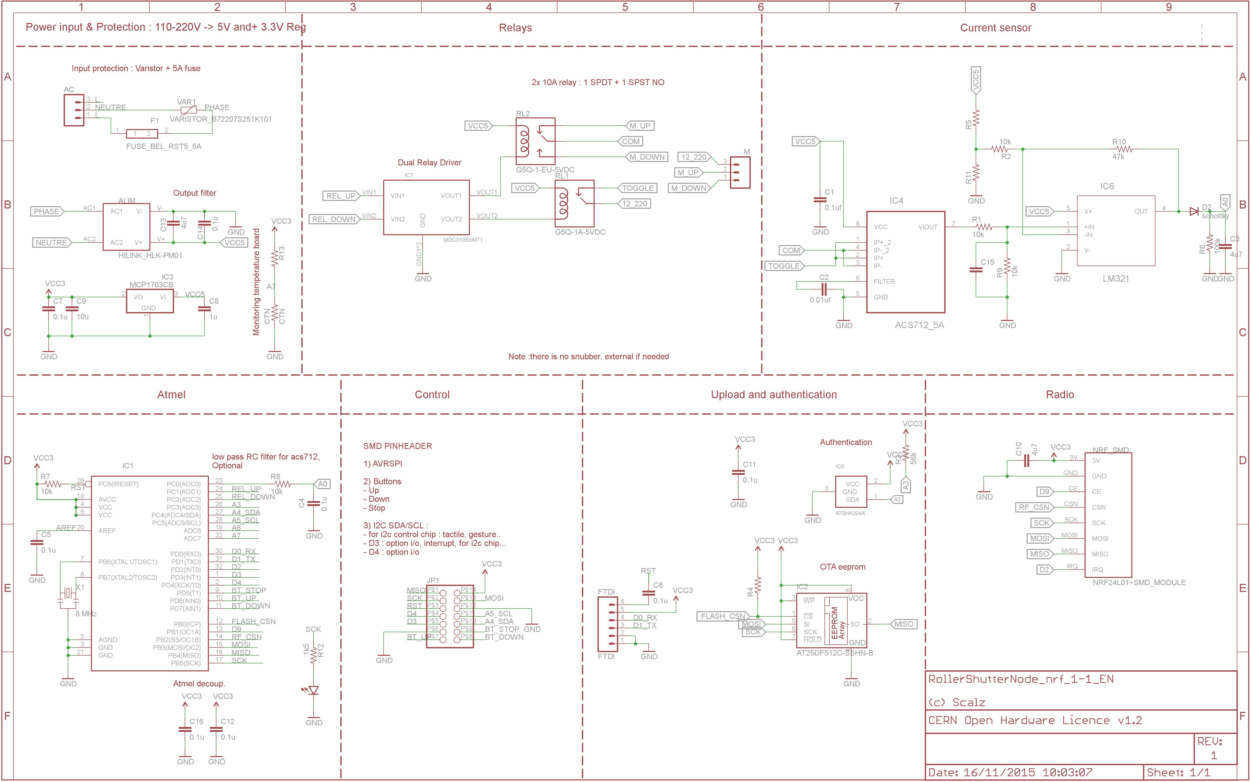
    On-board, there are 2x10Amp Relays. Rollershutter motor don't use 10Amp of course, nor 5Amp. So maybe if relays are 10Amp rated, no need of snubber (I hope). If needed, it should be external, there is no enough space onboard.
    That said, for a simple relay board too, you can control lot of thing with 10amp.
    So, we have 2 relays, for a rollershutter:

    • 1x NO : which enable/disable power on the second relay. It is like "Stop Motor".
    • 1X NO-NC. you can toggle it, and drive Up, or Down the rollershutter motor. Remember this relay need to be enabled by the previous one.
      So relays are "interlocked", you can't enable "Up" and "Down" outputs to motor at same time and burn your motor.

    How to open/close 0-100%

    • We need to know the up and down ends. It is managed by the onboard ACS7125 sensor. It senses motor current flow and we read it with ADC on arduino. So when motor is active, we have a power consumption.
      When an up or down end is toggled, the motor stops (because of mechanical switch...). So there is no power consumption. So you can see, with ACS712, we can know in which state we are. We are able to read some kind of power consuption curve too if needed and no mechanical ends switch available..
    • We need to know how long it takes to open the rollershutter, and to close too (it may be not the exact timing open vs close time). So, here it is a story of millis chrono, taking some sample, making average etc...software stuff
    • good care of states in the sketch. no loop inside to not block anything, etc...

    General specs (also visible on my github) :

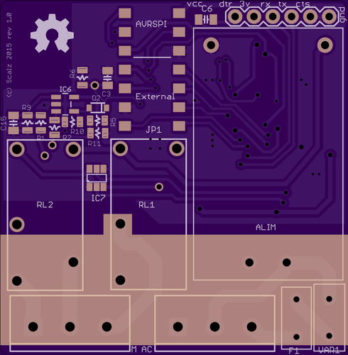
    • Components size 0805. Board size 47*48mm.
    • Can drive 12V up to 220V motors (for 12-24V just connect power source to PWR connector, for 110-220V connect one L connector to PWR connector)
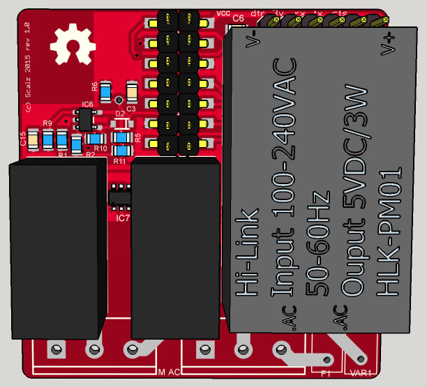
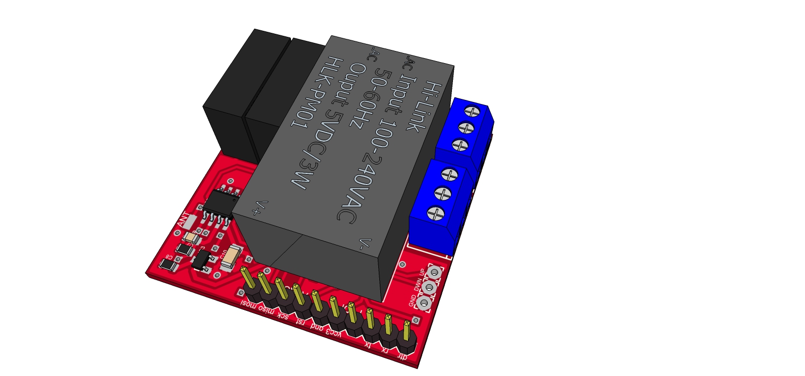
    • AC/DC step down 220v-5v
    • 2x10amp relays, G5Q type, 1xNO, 1xNO-NC
    • ACS712 0-5A current flow sensors
    • Inputs for UP, DOWN, STOP
    • Some securities. On AC input, there are varistor+5Amp fuse. A CTN thermistor, on pcb bottom, under the AC/DC step down, to know board temperature in case. A dual relay driver to manage relays and parasite.
    • ATSHA chip footprint for authentication
    • Eeprom chip footprint for OTA update
    • Connector for ftdi
    • Connector with AVRSPI, I2C for external breakout (tactile switch, gesture...), 2 available I/O (D3 int, D4)
    • two versions : NRF24 smd or RFM69(H)W
    • Screwterminal 5mm pitch

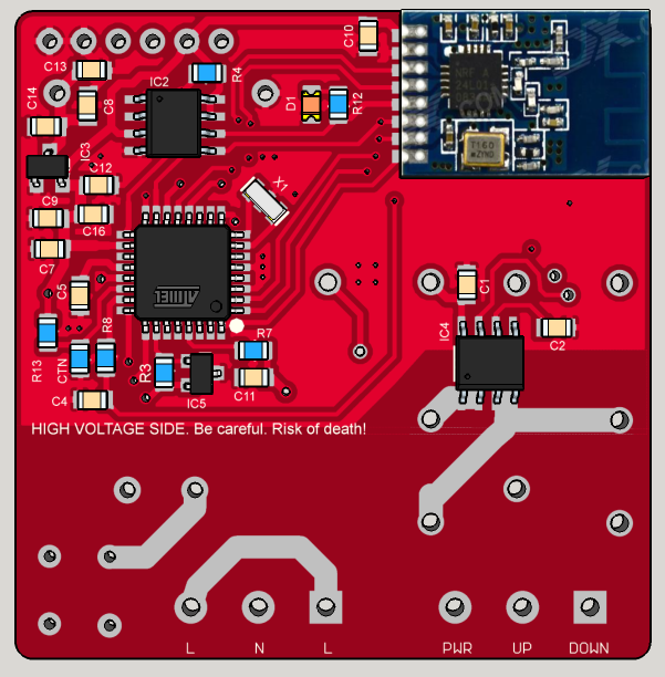
    Here is the schematic:
    Schematic_nrf_1-1.png
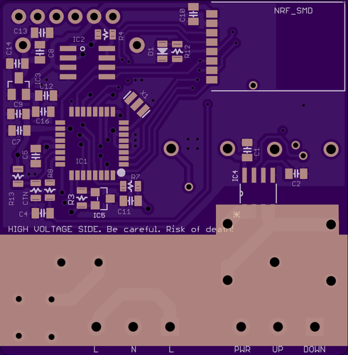
    Here some pcb views:
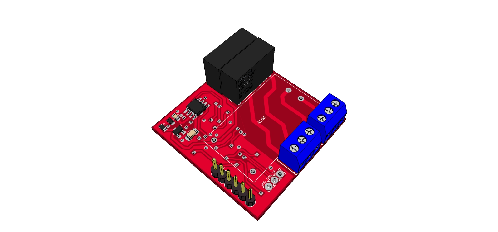
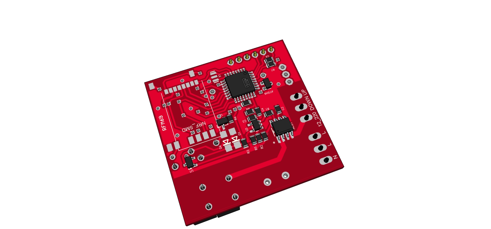
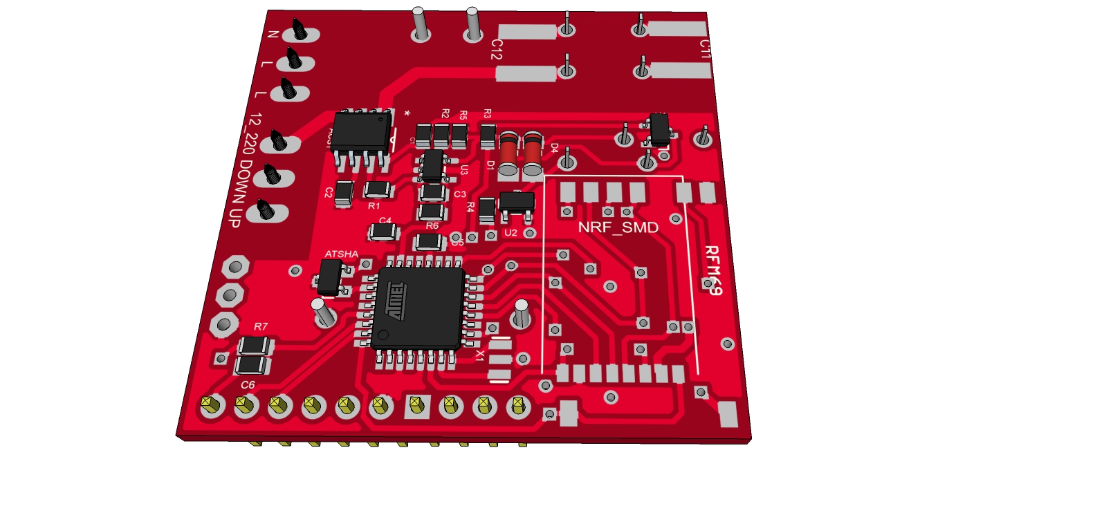
    top_pcb.png
    bottom_pcb.png
    Some 3d views:
    top_overview1.png
    bottom_overview.png
    For fun, a first idea for a rollershutter custom box, with holes on cover for luminosity+gesture
    https://www.youtube.com/watch?v=bKaH_GUuFAI

    Sketch
    Sketch is almost done but not tested yet. I will post an example soon, before I need to clean and update it as it was for my previous rev.

    All my files (including gerbers) are here : https://github.com/scalz/MySensors-HW/tree/development/RollerShutterNode

    Important
    **Note **: it is a project in progress. I repeat it just in case lol. It is hobby, opensource, and I share the little time I have for this with others projects in progress too. It costs some money of course, we are all in same boat with diy. So all these parameters can make the project longer. Very sorry for this
    But all the stuff is almost done. It just need to test now!
    Note 2 : As I said, I debugged my previous rev. All seems good, but I don't want to say it is a stable version until I am 100% sure.

    Thanks for all your feedbacks.


  • Admin

    Great! Really like the idea of detecting end-stops.


  • Hardware Contributor

    @hek thank you! yes it would be coool.

    It is not tested yet. I need to test it before send to fabhouse.
    For detecting, I am thinking about sensing current consumption on motor. I hope acs712 will be do the job (I think with 610mv/A, it could handle small 90w motor, i should have something like 120 on adc...). If people have best ideas...
    For detection:

    • reset : up until end stop detected.
    • then calibration begins : start timer and down until end stop. Get the down travel time.
    • then start timer and up until end stop. Get the up travel time.
    • you can do another time and abs.
    • then store in eeprom
      To start calibration : button sequence or v_light command
      And V_DIMMER to set your roller shutter with sunlight, temperature...
      I think, it will need some adjustments (if the motor have a capa, relay response...).

    I am a little disappointed because i was hoping to make something smaller but i would like to stay simple for others (mini pro, 1206 size...). and transfo takes place too! But it stays 5x5 ratio so cheap at fabhouse.


  • Hero Member

    @scalz , wonderful project, thanks for the initiative! With minor changes the board can also be used as a "mysensor dual-relay" (within consumption meeter) --- It is really very nice!

    One suggestion so far, maybe an Resistor-Capacitor "Snubber" between relay contacts, in order to prevent relay DC Arc?


  • Hardware Contributor

    @rvendrame : I was thinking about dual relay too! Good idea for the snubber, thank you. I did not think about this even I saw it in a datasheet yesterday, argh, my lack of knowledge (I have not some automatics yet). So I am happy to show you for this. I will check for the snubber and hope it will find its place! I missed some creepage too. and will add a capa near my adc.
    if it can help people, I am more than happy!


  • Hardware Contributor

    So, here my files (need to be tested) : https://github.com/scalz/MySensors-HW/tree/development/RollerShutterNode_small
    Now I will work on my sketch and release when all will be ok.


  • I follow your work. Very interresting.


  • Admin

    @scalz

    One question, why use an arduino board on top of it? You could just add the atmega chip directly to your board. You have SMD components on it anyways, so one more or less, is nothing..


  • Hardware Contributor

    @tbowmo : I agree with you. and I was thinking to do like this. But if I had choosen this way, I would have used 0805 (but not under, it makes me nervous, lol) and maybe using lnk306 or tny to have compact transfo. So it would be less fun for those who just want to take files and are not friend with soldering. So I have 1206 (easy to soldier), and you are right there are some small ics but just a few... But it's sure, those who take files knows soldering I think.

    Humm, you are tempting me to try to make it smaller version but I have others projects..You are right it could be smaller...I will see.

    Thank you , I'm very interested with your feedback. I am learning a lot here.


  • Hero Member

    @scalz , it looks you will power the motors from AC Mains (through Fuse F1 + ACS712). Maybe you could add a side track for those who want to use 12V or 24V motors instead?


  • Admin

    @scalz

    I would suggest that you look at kicad instead, we have some mysensor specific parts in a common repo on github. Look at mysensors-kicad project on github


  • Hardware Contributor

    @rvendrame: exactly, I saw my mistake today. I will update files soon.

    @tbowmo: thank you for advice. next time I will think about it.
    For mysensors kicad project, wow, thank you for the link. team mysensors is making a great work. I noticed last weeks there is a kicad movement.
    Too bad I started to learn Eagle some months ago and I am just starting to like it. What I like too with eagle is lots of libs, and that I can get some footprints at farnell. But in other hand when I see all of your projects with 3d rendering, it is very hard to not have a look. And kicad is opensource...and if I can contribute..


  • Hardware Contributor

    I updated screenshots and my github files. Now I think it can handle 12-220v motors. I had to change screw terminals (it was 5mm before, 3.5 now, i hope it is good). I have no place for capa snubber (too big unfortunately ) it will have to be external if needed. And I removed fuse too. Because it could change if 24v or 220v motor (not same current for 90w-24V and 90W-220v) and it is not easy to place it. So it will have to be external too if needed.

    In case using 220v motors, now it needs to tie together Source and 12_220(Live) at the screw terminals.

    I will see if I can make it better and smaller in the future (to put it in wall) and designed with kicad😉


  • Hardware Contributor

    Hi,

    So, I tried to reduce size board to be able to fit in wall. I thought about using switching ic or to use sealed ac dc step down. not very easy choice but I keep the sealed (for galvanic protection), because I think it should not gain so much space finally and sw ic is more expensive to use. RFs footprints, atmel, eeprom... takes place too.

    Here is how it looks for the moment. I just tried 3d for eagle to see so 3d rendering not complete.
    It is 42x43mm
    Top: power, relay, ldo reg, eeprom, ftdi connector.
    Untitled.jpgBottom: atmel, atsha, acs712, nrf smd & rfm footprint
    it is almost 0805 (i am just seeing I missed 2diodes).
    Untitled2.jpg

    But as you can see there is no snubber? I am thinking to add a capa only. Do you have a good not expensive ref smd that I can put on bottom.??
    And there is no AVRSPI connector for the moment I need to find a little place for it, not easy.
    Any remarks?

    See you soon


  • Take car about antenna position (no metal just under the antenna). I experience some issues with sensebender micro and FTDI connector just under the antenna. And perhaps you can use small SSR relay.


  • Admin

    @scalz

    As @Fabien just mentioned, you should keep the area under, and around, the antenna of the NRF clear of any tracks, and components.. Otherwise you are asking for trouble..


  • Hardware Contributor

    @Fabien @tbowmo: thank you very much for your feedback.
    So no tracks under the chip, or on the other plane? Arrgh, I will try. Is it related to nrf because on moteino designs it seems rfm don't care about it? Anyway I don't want to have problems. I don't know how I will do that but I will see this evening.Last night, I added spi for programmer so it's cool. I found capa for snubber but 2220 size...

    And for small SSR, I thought about it but the board must handle 12/24v motors too so current won't be the same and small SSR won't like that. That is why I choosed these relays. I want to be able to handle 12/24 and 220v so the board would be useful for lots of application.
    I was lazy to move to kicad but I will move for sure 😳


  • No track under the chip. I use kicad for few years now and it's ok !


  • Hardware Contributor

    @fabien: so not under chip, but other side of board is ok i think? Anyway, I think I will have to do some reroute. Not easy. I am not electronician. I'm database soft archi. So I have not done lots of pcb yet. I am learning.. but at my job I played a lot with mikroelectronika even if I am not in charge to design pcb.
    And I think I made a wrong choice with eagle (I saw lots of libs so I thought it would be easier. But I have to make lots of parts myself so...).
    Here what I did last night : moved ant smd for rfm, spi connector, and 3d model for stepdown. Not a lot of things. And, tried to place snubber, but not good, clearance drc errors..I am thinking to add snubber externally.
    Untitled.jpg Untitled2.jpg Next screenshot I hope all will be ok 😃

    @tbowmo: which tools do you use to create 3d models for Kicad? I tried Sketchup yesterday but don't like interface as I usually use Solidworks at job when needed. Would be great if I could export Solidworks to kicad, I will see if it's possible..


  • Admin

    @scalz

    rfm modules have an external antenna, that is why they can be mounted like they do on moteino boards.

    NRF modules incorporates an anteanna, and you need to keep the anteanna area (+ some space around it) clear of components and tracks. on both sides of the PCB. Otherwise they will interfere with the antenna radiation.

    I use the build in 3D viewer in kicad. (Using almost bleeding edge of kicad on linux, with additions from CERN)


  • Hardware Contributor

    @tbowmo: thank you for your explanation. So I think it is not a good news for me (nrf24) aaaaaaa I will loose my hairs on this😅 even if I plan to use rfm, my brother have a lots of nrf24. I think he will need move to rfm. But I will try, big challenge for me.
    For kicad, interesting info, thanks.


  • Hardware Contributor

    @Fabien: I have an idea for nrf24 problem, maybe dumb I don't know.

    • on bottom of nrf, paste piece of paper
    • then add a piece aluminium sheet or anything else with a wire to connect it to gnd
    • then paste another piece of paper
      Do you think it could work? Or maybe antenna will not like the ground plane...
      just ideas, in case.

  • Admin

    @scalz

    A gnd plane under the antenna are sure to make troubles, as you effectively short circuit the antenna.


  • I have the ftdi header on the sensebender board mounted on the atmel chip side (opposite the radio) and have not had any problems with radio range or packet loss. My deployed sensebenders are all between 3 and 7 meters from gateway or repeater.


  • You can have no problem but sure metallic part modify the diagram antenna. Perhaps with real Nordic there's less problem but for new design it is better to avoid ground plane or tracks on all layers under the antenna.


  • Hardware Contributor

    @tbowmo: ok. so in my case it is not a good idea to put 2 radio footprints as it will increase size. As I have already done the job, I will make 2 versions. easier.
    In the other hand, the mini pro version (a little bigger) I have already traced could handle both radio with some minor change.

    So, I have now all recommandation I need. So I am able to finish it and send to fabhouse for test. I will inform you when board and sketch all done.
    Thanks again to all.


  • Hi @scalz

    A question, there is a reason to do not use an encoder instead of the acs712 and the stop buttons to know the position of the shutter?

    Cheers


  • Hardware Contributor

    Hi.
    I am not sure what do you mean with "stop button" (end stops?) and encoder. I have made this board for multi purpose, not rollershutter only. And in dualrelay, I can know power consumption too.
    I need to update 3d view. But my schematics and pcb are my latest rev. I am waiting for my pcb (end of the month).
    Maybe there are other good ideas as I am not electronician. But I have learnt a lot at my job and thx to internet😄


  • Hardware Contributor

    Hi.

    just to share 😄 as I have received some boards today. so here a screenshot for rollershutternode.
    Sans-titre-1.jpg
    It is not soldered yet, I just wanted to see if my hilink, relays and nrf footprints was ok. it's ok! but too bad I forgot to order varistor and fuses (fuse will be between the screw terminals, and varistor on right bottom corner...
    these boards was ordered at Seeed.


  • can you please tell me that what type of roller shutter are use....
    where I can buy this roller shutter.


  • Hardware Contributor

    @jemish: I will test it on somfy rollershutter (220v motor). but the board can be used with 12-24-110v motors/load. and I need to finish the rollershutter sketch too and check everything.All will be ok in maybe... two weeks I hope.


  • It's exactly what I want. Dimension are fine (fit in wall european round european box). I can't wait 2 weeks 😂


  • @scalz : what the news ? Did you test your board ? I will start a design without Hi-link (LNK306 Or SR086 instead) and triac and I would like to know if you can use current information from hal-effect sensor.


  • Hardware Contributor

    @Fabien: yes I have done some tests and worked on the sketch too.
    So for rev 1.0, I have made a mistake on opamp of acs712. not big but a little embarrassing to fix onboard.
    Good news is I have no stability problem (regarding relays, button interrupt, or smd nrf near buttons pinheader). I was afraid about that. so it's cool.

    Rev 1.1 is finished (but not ordered) and I am working on documentation before release. it won't take long time I hope 😉
    In rev 1.1 :

    • opamp for acs712 updated
    • 0805 onboard led added (was missing but it can be useful!)
    • 0805 CTN for temperature of the board (under hilink)
    • better silkscreen

    for your question about triac and acs712, I can't tell you. I am not sure, but don't see why it could not work. but if it is for rollershutter node control, I am not sure if triac is best option..


  • I don't think relay is a good option for 230VAC motors. On start current is very high and relay's life will be short. And second problem with SR086 for example I have only 60mA under 3.3V, It could be a problem for NRF+ATMEGA328+Relay command (transistor).
    I prefer to chose triac like ACST8-8G (DPAK) wich is fine for controlling motor and very small.


  • Hardware Contributor

    @Fabien:
    cool. it could be interesting. I thought about triacs and making my own power supply too and for lots of reasons I choosed relays and hilink.

    • I wanted something the most secure and galvanic isolated.. and for triac you would need an opto. then multiply by 2 for Up and Down. So for one rail, counting all components involved, footprint is near relay, maybe bigger.
    • omron relays are small and not power eager. I don't enable two at same time for rollershutter motor.
    • triac makes more emi. Add to this an homemade powersupply...I wanted to be sure for radio..
    • I think fibaro rollershutter uses relays (two). If triacs was a good option I think they would have used it as they uses triac in others products. but I am note sure, I have none of these. I just looked at their docs.

    Anyway, your way is interesting too! try and test I will follow your work for sure 😉


  • @scalz : at this time, I 'm only explore different ways. I've got some HI-LINK but in your design i'm not sure it fit with an enclosure into a 67mm wall box.


  • Hardware Contributor

    yes I understand. I thought exactly about same problematic. my design is 47x48. I was hoping to make smaller too.
    another cool idea could be to make custom wallbox...with touch sensor plate or gesture recognition.


  • @scalz
    I'm following this post closely I like the idea, I have some motors controlled via RF but I don't like the controllers or the reliability. I will see how to retrofit them with your controller after you have tested and did all the hard work! 😉 I believe I can just Hijack the motor wires and use the relays and the boards for all the logic. I like what you have setup but I will have to see your sketch first.

    I have some old Hunter Douglass motorized shutters that use IR remote I hacked them with an reed relay on a node that acts as a push button. Just like pushing the button on the motor. Unfortunately the new shutters I got don't have a manual push button or I would do the same.


  • @scalz any news ? I just find this library (from @Marvin-Roger) : https://github.com/marvinroger/arduino-shutters
    After few days, I think you are using the right way with HI-LINK and Relay. It coud be better to user interlocking between relay becaus shutters doesn't like to have AC on 2 inputs simultaneously (and will be dead). This can be a problem. But you have to find relay with 2 poles.


  • @scalz any news ?


  • Hardware Contributor

    @Didi: sorry, I am very late on my projects. Busy at my daily job. some projects not presented yet; and those which I started here too..and actually I have some projects in teamworking with Charles from hallard.me...gloups! I don't sleep too much, tired, but it's ok 😉

    So for this project, some changes that I have done recently (thx to @Fabien for his ideas too 😉 😞

    • bigger relays and interlocking between them : 1x10A NO and 1x10A NO-NC
    • tvs diode, transistors...replaced by MDC3105dual relay driver: smaller footprint
    • some reorganization : now I have enough place to make another board and replace nrf with rfm.

    These changes mean that it is not a pure dual relay anymore. Too bad for me as I wanted something dual relay+shutter. But I have still my previous dual relay design. So now I have two boards to update! First, rollershutter (I will try to upload my files tonight, I hope, not sure...) and dual relay board (same thing...).Did I say that I have not enough work 😆 ??

    something important to know is this new rev is not tested, and boards not ordered yet. Of course, I have debbuged things, and it should work. I know someone who wants to order it but I have not given to him my files yet. Thanks to him, it is to participate to money and debug, as it costs money to dev...


  • Hardware Contributor


  • SSR is not a good solution because the snubber depends on loads. And zero crossing triac could be a problem with motors (phase between current and voltage). And with SSR you can't have interlocking between up and down (could damage your motor). Finaly in term of space, you have to put a varistor so it's not smaller than the relay scalz use.


  • Hardware Contributor

    Hi.
    I have updated my git and my first post with details about my latest revision of this board 😃
    I just need to check one or two things on the BOM before upload it too.


  • Just soldering. Missing some componments.
    0_1453327912240_IMG_20160120_230900.jpg


  • Hardware Contributor

    👍 too fast! I have to run now, ahaha 🙂


  • Board finished.
    Test :

    • ATMEGA328p ok. Setting fuses and loading optiboot/DualOptiboot.
    • LED ok 🙂 (blink test) With DualOptiboot you need to reset device after uploading new sketch.
    • ATSHA ok with test exemple
    • EEPROM ok with Write/read test
    • Realys ok wit simple commands.
    • Regulator 3.3V Ok

    Need to test : Radio (RFM69W) and current sensor.

    Some photos :
    1_1453846320559_IMG_20160126_225347.jpg 0_1453846320558_IMG_20160126_225334.jpg


  • Hardware Contributor

    great news 🙂 thx for helping me on this 😉
    for AC connection insulation on bottom, I am planning to use pcb varnish and liquidtape. Liquidtape is not so cheap, but can be useful for other things..


  • Last news ! Radio work ok and MySensors too.
    Upload RelaySketch and I can control relay with MYSController ! Wow !


  • Plugin Developer

    Hi!

    Great news! I've been waiting for this board to be tested and approved.

    Is it possible to use the two relays to control two individual lines, for example two different lights? I read above that for the roller shutter function with a motor, the relays were interconnected. But If the use case is plain switching lights, can you work around this easily?


  • can we control our windows curtains using this????


  • Hardware Contributor

    I have uploaded it on openhardware. I still need to upload the BOM, as I need to make better the linl between my git, I have to enter my BOM manually for the moment.
    I will put some real pics soon too, or maybe yours @Fabien ?

    @martinhjelmare : the first rev I did was like you want, two relays in parallel for individual lines.
    But guys asked me (here and at jeedom) if instead, I could interconnect it to protect the rollershutter motor. They were right so I made the change. Unfortunately, this can't be changed on the rev2. I wanted to do it but I had not enough room onboard for route cleareance...
    But I will upload my first rev asap, I am already using one at my job. I just need to check if my files are ok 😉

    @jemish: if it is something like rollershutter node motor, it should work. I don't know what do you mean by windows curtains. Can you show me what is it please?

    Last note, the 0-100% opening depends on the ACS712. I have not tested yet on this new rev, nor Fabien. It's in a very good progress 🙂


  • @scalz You can take my pics.


  • @Fabien I can't see the antenna on your pictures, where is it ?
    Could you tell me the actual height please (RFM69W version) ?
    If I correctly read the thread, I understand that the dimension are 47x48, is it right for RFM69 version ?


  • @fets you're right, on the pics, antenna is note present (8.2 cm wire). Height is 2cm. Board size is the same (47x48 mm) for both NRF24 and RFM69 versions.


  • @Fabien thanks, good news.


  • @scalz said:

    Last note, the 0-100% opening depends on the ACS712. I have not tested yet on this new rev, nor Fabien. It's in a very good progress

    How are you doing on the 0-100% code function?
    Im doing the same thing for a greenhouse sides opening controller using 2 relays and V_PERCENTAGE.

    Im not having great luck at the part of passing the value from the controller to the function to execute running for X number of milliseconds (will add the current sense you suggest later it is a great idea but trying hardcoded travel time for now)

    Just wondering if you had any code to share that could shed light on my current project.

    thanks


  • Hardware Contributor

    @jserfaty I will try to share some code as soon as possible, sorry being late on this. Bzzz, bzzz I'm like a bee sometimes 😆
    In sketch, I will have two options:

    • automatic calibration with current sense..
    • or a fixed calibration, a time travel set in sketch.

    So I will try to look if I have nothing ugly in my sketch asap (there is already someone waiting for this ;))
    And a note, for others, about the board, I'm thinking to reduce size if possible to fit better in wallbox but I would like to keep hilink.


  • Maybe look at this one: Arduino shutters

    I am using this one with my 8ch relay board. Working fine here!


  • Hardware Contributor

    @kenci yep I am using this one 😉 it's time based in the sketch. and nice class.
    I just need to add an auto calibration if using current sensor


  • @scalz, I love this project. I am waiting your last changes (in a code), then I wold test it in my home!, thank you very much for share it.

    Antoni.


  • @scalz are you going to sell this on openhardware.io as a complete module?


  • Hardware Contributor

    @kenci I think so...this is a very nice new feature on openhardware, not only for commission (sure that could help a little bit for dev cost..) but, more interesting is to have competitive price for some device and make these available for others, that's excellent 🙂 I can't wait to test this, to see what will be the quotation..I will try to do my best 😉


  • Hi @scalz great work i am working a project like yours but i do not understand teh principle of MDC3105. The shematic i made like yours is below, search a little but don't find anything about it. Is it correct without any resistor, diode etc.?
    alt text

    The normal schematic is below with diode, resistor, transistor etc.

    alt text

    Thanks for share it.


  • Hardware Contributor

    @ddos Yes, that would work - if VIN1 is pin 5, VOUT1 is pin 6, VIN2 is pin 2 and VOUT2 is pin 3, that is.

    It's a bad habbit to have "double pins" in the schematic. You should really make a pin for each ground connection - just my 2 bits.

    BR Jonas


  • @jbjalling thanks for your quick reply. If this is gonna works without any additional parts my board has more space. I copy the device @scalz schematic i am going to do new library with two GND for it thanks again.


  • Hardware Contributor

    @ddos
    jballing is right. the relay driver already handle this. it's integrated, less footprint. be careful playing with AC, you need to know what you do 😉

    btw I am a bit cheap on pics and late I know 😊 a bit busy too but few pics of what it looks..
    0_1465407734791_roller_2.jpg
    0_1465407764538_roller_1.jpg

    45x44mm seems to fit ok. millings for additional distance etc...


  • @ddos, Hi Srs., at first moment.. thank you very match to share this project, I like to try this project in my home but I don't know where are the library/code to try to use in my system., someone know where I can found it? 😉

    Thank you.
    Antoni.


  • @anarro sparkfun libraries is good you can find them on github and of course adafruit library. If the device you are looking for is not in the libraries you can find them on google 80% chance. If you can not find them on net you should do your own devices.


  • @scalz your pcb and cutouts look very good for voltage protection but i think you need a case for 230V AC pins which are touchable right now.


  • Hardware Contributor

    @ddos
    thx. of course! i will print an insulating box with some air vents. and i will add some liquid tape for isloating the pads 😉

    for software, i need some time to clean and test it. and i am playing with others things+ etc.. I already shared the sketch with only one beta tester here, for the moment. but of course i will share it asap 🙂


  • Made my first test tonight. Only a proof of concept with the first board and without auto-calibration. Yes I know, I have only blue wire near me ...
    0_1465769942109_IMG_20160613_000909.jpg


  • @scalz Hi, I know that you work (I readed your another posts) with code to use with this board, with sensor current and auto calibrate options... so if you need..I can help you.. or I can try it...(-;

    Thank you.


  • Hardware Contributor

    @Fabien great 👍 .did you try the sketch too? I will improve it a bit 😉
    @anarro : thx. I will install one board at the end of the week and will try to make a small video of the thing actuated by another cool thing I am finishing 🙂


  • @scalz ok, I m waiting you news... good news!! 😉


  • @Fabien Great demo with blue wire 🙂
    It seems the board will not fit in the wall case behind the switch because of the height, did you try to fit it?


  • @scalz
    Hi, can you install and test the board?, do you have a some news??


  • Personnaly I wait for EEPROM (the one I solder are not compatible). And I will try autocalibration.
    And I will make PCB with the last version when release (smaller) and a plastic case (3D print) ... Lot of work !


  • What happened with this project? Has been abandoned or finished successfully?
    Have you tried automatic calibration?


  • Hardware Contributor

    Yes this is a finished project on my side.
    You can get more informations about this project here https://www.openhardware.io/view/22/Roller-Shutter-Node


  • @scalz Does the NOD works with domoticz? Is it possible to communicate with rs485?


  • Hi! Is this thread alive? I found this and it's a great piece of soft+hw. Immediately aborted my attempt and adopted this one.

    It has however some space for imrovements. So far I have identified two issues that I needed to correct:

    1. Report current position of the rollershutter. It's needed by my controller (openhab via mqtt) in order to show the real position of the shutters. It's working.

    2. The openhab controller also happens to have reversed the 0-100 percent concept of closed/opened, so I reversed that in software.

    Are you interested in having some pull request with these modifications? I'm glad to do that.

    Thanks a lot for your effort.

    Regards


  • Hi @Guillermo-Schimmel , right now I'm just trying to do what you did. I'm interested in building a home automation system based on openhab and a raspberry pi from scratch, which reliably controls the roller shutters at home. I have already built one in the past, very basic, which using some relays turns on and off the lights and allow to simulate the pressure of the buttons at home raising and lowering the blinds. However it lacks to indicate their real position, and moreover, by pressing physical buttons at home, their new state (fully up or down) can not be communicated to openhab, so I can't know if they are really up or down. So I decided to start from scratch building also a new control unit for the shutters. The hardware of this project is extremely interesting, but I can not figure out how to interface it with openhab.
    My idea would therefore be to build two control units, a primary - which I will use for the lights and other sensors, very similar to the one I already built and use - and a second one dedicated to the shutters, based on this project but with the possibility to manage five shutters and connected to the first with serial or rs485 (they would be very close, so I would avoid the radio section with attached authentication). Can you help me, giving me information about the connection between this project and openhab, so I can succeed in this little adventure?


  • The combination openhab (2.3)+mqtt (mosquitto)+mqtt gateway+mysensor nodes works perfect end to end.

    The rollershutter node, with a small addition to report position works perfect just as-is.

    I wouldn't try to do the comms other way than nrf24 (perhaps nrf5x in the future). It's cheap and easy.

    If you have some specific question I will be glad to help you. I'm convinced OpenHAB is the best home automation controller, but sometimes can be a little difficult to start things up.


  • Hi. I am building the roller shutter node myself and i am in trouble for programming it.
    I have an USBASP connected to it but i can't figure out.
    I install the driver, but when i try to burn bootloader from arduino program i have an error.

    Arduino : 1.8.5 (Windows 10), Carte : "Arduino/Genuino Uno"
    avrdude: warning: cannot set sck period. please check for usbasp firmware update.
    avrdude: error: program enable: target doesn't answer. 1 
    avrdude: initialization failed, rc=-1
             Double check connections and try again, or use -F to override
             this check.
    

    I try with a stock arduino uno and it's working fine.
    Do i need to tweak something cause on the shutter node there is a 8Mhz clock ?
    Or i just fail soldering ?

    Thanks


  • I really don't know, I can't help you much. My sugestion would be to back down to a simpler sketch like blink, use the standard arduino ide and try everything. Just then move to more complex projects like roller shutter.


Log in to reply
 

Suggested Topics

  • 87
  • 8
  • 2
  • 10
  • 5
  • 9

0
Online

11.2k
Users

11.1k
Topics

112.5k
Posts