Sprinkler Controller
-
Hi all,
Inspired by @BulldogLowell's Irrigation Controller, I set out to build a controller to work in conjunction with my RainBird Controller. The primary reason for doing it this way is that the RainBird controller is very reliable, albeit not very smart. I wanted additional smarts, but did not want to forego the reliability of the RainBird, so I set out to build a controller that has the best of both worlds. The controller is still a work in progress, but the base functionality is now in place and I will hook it up this weekend. All of the smarts are in my HomeSeer 3 HA system (HS3), so right now the Mega just listens and processes commands from the HS3 MySensors Plugin. The HS3 MySensors plugin does not support the retrieval of variables used in BulldogLowell's controller, so I had to do things slightly different. I'll post my sketch in a few days.
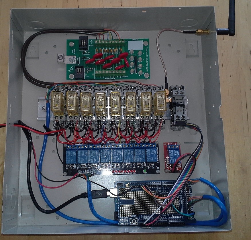
As you can see from the picture below, there are 3 sets of relays:
8x 5VDC Relays controlled by the Arduino
8x 24VAC Relays controlled by the 5VDC Relays and the outputs of the RainBird Controller (wiring to the RainBird not shown)
2x 5VDC Relay which is used to activate the rain sensor input on the RainBird controller and is used for the controlling the main valve (needs to be installed). Activating the rain sensor input effectively bypasses the RainBird controller.The 24VAC relays are DPDT and I'm using one pole of each relay as an input to the Arduino. That way I can detect if the RainBird is controlling a zone and also whether the command to activate a relay by the Arduino was successful. The second pole of each 24VAC relay is used to control the actual zone valve. The outputs of the 24VAC relays are connected through a surge protector that I had bought a few years ago to use with a different controller (the ground wire is not connected yet and the wires from the surge protector to the valves are not shown).
Here are the components used in the controller:
- Arduino Mega
- Arduino Mega Prototype Shield
- NRF24L01+ with PA/LNA mounted to a spare relay socket
- SMA Female Bulkhead
- SMA Extension Cable
- 2 Channel Relay Module
- 8 Channel Relay Module
- 16x2 LCD Module
- Idec SY2S-05C Relay Sockets
- Idec RY2S-U-AC24V Relays
- Aluminum Slotted DIN Rail
- TManufacturing Sprinkler Surge Protector
- DSC Alarm Panel Enclosure (door not shown)
- Terminal Strips
- 24VAC to 5VDC Power Supply
- Cables: CAT5e to interconnect relays to the Mega, 7 wire sprinkler cable, Dupont cables, etc.
Still to do:
- Connect and update the sketch for my DLJ Water Meter that will be installed on the water line for the sprinkler system. This way I can detect if a sprinkler valve is stuck open (i.e. if all of the valves should be closed, but there is still flow, then there's a problem).
- Update the sketch with a watchdog timer. The Arduino will try and connect to my HS3 system on a regular basis and if it fails for a period of time, the relay for the RainBird bypass will open, allowing the RainBird controller to take over.
- Add a 24VAC to 5VDC power supply so that I don't need to use two separate power supplies. The 24VAC supply is shared between this controller and the RainBird.
Cheers
Al -
very nice!
Extending the radio antenna is a nice touch too.
:+1:
-
very nice!
Extending the radio antenna is a nice touch too.
:+1:
@BulldogLowell Thanks and thanks for the inspiration :-)
-
Hi all,
Inspired by @BulldogLowell's Irrigation Controller, I set out to build a controller to work in conjunction with my RainBird Controller. The primary reason for doing it this way is that the RainBird controller is very reliable, albeit not very smart. I wanted additional smarts, but did not want to forego the reliability of the RainBird, so I set out to build a controller that has the best of both worlds. The controller is still a work in progress, but the base functionality is now in place and I will hook it up this weekend. All of the smarts are in my HomeSeer 3 HA system (HS3), so right now the Mega just listens and processes commands from the HS3 MySensors Plugin. The HS3 MySensors plugin does not support the retrieval of variables used in BulldogLowell's controller, so I had to do things slightly different. I'll post my sketch in a few days.
As you can see from the picture below, there are 3 sets of relays:
8x 5VDC Relays controlled by the Arduino
8x 24VAC Relays controlled by the 5VDC Relays and the outputs of the RainBird Controller (wiring to the RainBird not shown)
2x 5VDC Relay which is used to activate the rain sensor input on the RainBird controller and is used for the controlling the main valve (needs to be installed). Activating the rain sensor input effectively bypasses the RainBird controller.The 24VAC relays are DPDT and I'm using one pole of each relay as an input to the Arduino. That way I can detect if the RainBird is controlling a zone and also whether the command to activate a relay by the Arduino was successful. The second pole of each 24VAC relay is used to control the actual zone valve. The outputs of the 24VAC relays are connected through a surge protector that I had bought a few years ago to use with a different controller (the ground wire is not connected yet and the wires from the surge protector to the valves are not shown).
Here are the components used in the controller:
- Arduino Mega
- Arduino Mega Prototype Shield
- NRF24L01+ with PA/LNA mounted to a spare relay socket
- SMA Female Bulkhead
- SMA Extension Cable
- 2 Channel Relay Module
- 8 Channel Relay Module
- 16x2 LCD Module
- Idec SY2S-05C Relay Sockets
- Idec RY2S-U-AC24V Relays
- Aluminum Slotted DIN Rail
- TManufacturing Sprinkler Surge Protector
- DSC Alarm Panel Enclosure (door not shown)
- Terminal Strips
- 24VAC to 5VDC Power Supply
- Cables: CAT5e to interconnect relays to the Mega, 7 wire sprinkler cable, Dupont cables, etc.
Still to do:
- Connect and update the sketch for my DLJ Water Meter that will be installed on the water line for the sprinkler system. This way I can detect if a sprinkler valve is stuck open (i.e. if all of the valves should be closed, but there is still flow, then there's a problem).
- Update the sketch with a watchdog timer. The Arduino will try and connect to my HS3 system on a regular basis and if it fails for a period of time, the relay for the RainBird bypass will open, allowing the RainBird controller to take over.
- Add a 24VAC to 5VDC power supply so that I don't need to use two separate power supplies. The 24VAC supply is shared between this controller and the RainBird.
Cheers
Al
Hello! It looks like you're interested in this conversation, but you don't have an account yet.
Getting fed up of having to scroll through the same posts each visit? When you register for an account, you'll always come back to exactly where you were before, and choose to be notified of new replies (either via email, or push notification). You'll also be able to save bookmarks and upvote posts to show your appreciation to other community members.
With your input, this post could be even better 💗
Register Login