Video How To - Monitor your Smoke/Carbon Monoxide Alarm
-
Hey Everyone,
I finally had a chance to make @ServiceXp's awesome Smoke Alarm monitoring project and I thought I'd make a how to video. I am making a separate forum post because my code is a little different to account for detecting Carbon Monoxide. But you should check out his original post (http://forum.mysensors.org/topic/934/mysensoring-a-kidde-smoke-detector-completed) for more details. His method is more universal so if this method doesn't work with your alarm his probably will. Thanks for making this possible @ServiceXp!
Also, credit goes to http://www.edcheung.com/automa/smoke_det.htm for info on how to use the interconnect feature.
Ok, here is the additional info:
https://youtu.be/mNsar_e8IsI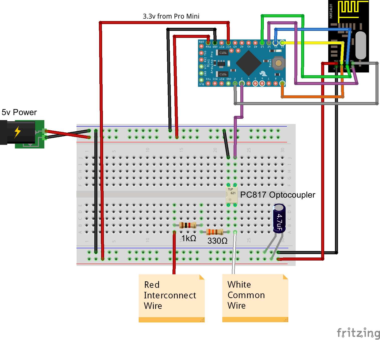
/* * Based on Author: Patrick 'Anticimex' Fallberg Interrupt driven binary switch example with dual interrupts * Code by 'ServiceXP' * Modified by 'PeteWill to add CO detection * For more info on how to use this code check out this video: https://youtu.be/mNsar_e8IsI * */ #include <MySensor.h> #include <SPI.h> #define SKETCH_NAME "Smoke Alarm Sensor" #define SKETCH_MAJOR_VER "1" #define SKETCH_MINOR_VER "1" #define NODE_ID 11 //or AUTO to let controller assign #define SMOKE_CHILD_ID 0 #define CO_CHILD_ID 1 #define SIREN_SENSE_PIN 3 // Arduino Digital I/O pin for optocoupler for siren #define DWELL_TIME 125 // this allows for radio to come back to power after a transmission, ideally 0 unsigned int SLEEP_TIME = 32400; // Sleep time between reads (in seconds) 32400 = 9hrs byte CYCLE_COUNTER = 2; // This is the number of times we want the Counter to reach before triggering a CO signal to controller (Kidde should be 2). byte CYCLE_INTERVAL = 2; // How long do we want to watch for smoke or CO (in seconds). Kidde should be 2 byte oldValue; byte coValue; byte smokeValue; MySensor sensor_node; MyMessage msgSmoke(SMOKE_CHILD_ID, V_TRIPPED); MyMessage msgCO(CO_CHILD_ID, V_TRIPPED); void setup() { sensor_node.begin(NULL, NODE_ID); // Setup the Siren Pin HIGH pinMode(SIREN_SENSE_PIN, INPUT_PULLUP); // Send the sketch version information to the gateway and Controller sensor_node.sendSketchInfo(SKETCH_NAME, SKETCH_MAJOR_VER"."SKETCH_MINOR_VER); sensor_node.present(SMOKE_CHILD_ID, S_SMOKE); sensor_node.present(CO_CHILD_ID, S_SMOKE); } // Loop will iterate on changes on the BUTTON_PINs void loop() { // Check to see if we have a alarm. I always want to check even if we are coming out of sleep for heartbeat. AlarmStatus(); // Sleep until we get a audio power hit on the optocoupler or 9hrs sensor_node.sleep(SIREN_SENSE_PIN - 2, CHANGE, SLEEP_TIME * 1000UL); } void AlarmStatus() { // We will check the status now, this could be called by an interrupt or heartbeat byte value; byte wireValue; byte previousWireValue; byte siren_low_count = 0; byte siren_high_count = 0; unsigned long startedAt = millis(); Serial.println("Status Check"); //Read the Pin value = digitalRead(SIREN_SENSE_PIN); // If Pin returns a 0 (LOW), then we have a Alarm Condition if (value == 0) { //We are going to check signal wire for CYCLE_INTERVAL time //This will be used to determine if there is smoke or carbon monoxide while (millis() - startedAt < CYCLE_INTERVAL * 1000) { wireValue = digitalRead(SIREN_SENSE_PIN); if (wireValue != previousWireValue) { if (wireValue == 0) { siren_low_count++; Serial.print("siren_low_count: "); Serial.println(siren_low_count); } else { siren_high_count++; Serial.print("siren_high_count: "); Serial.println(siren_high_count); } previousWireValue = wireValue; } } // Eval siren hit count against our limit. If we are => then CYCLE_COUNTER then there is Carbon Monoxide if (siren_high_count >= CYCLE_COUNTER) { Serial.println("CO Detected"); //Check to make sure we haven't already sent an update to controller if (coValue == 0 ) { //update gateway CO is detected. sensor_node.send(msgCO.set("1")); Serial.println("CO Detected sent to gateway"); coValue = 1; } } else { Serial.println("Smoke Detected"); //Check to make sure we haven't already sent an update to controller if (smokeValue == 0 ) { //update gateway smoke is detected. sensor_node.send(msgSmoke.set("1")); Serial.println("Smoke Detected sent to gateway"); smokeValue = 1; } } oldValue = value; AlarmStatus(); //run AlarmStatus() until there is no longer an alarm } //Pin returned a 1 (High) so there is no alarm. else { //If value has changed send update to gateway. if (oldValue != value) { //Send all clear msg to controller sensor_node.send(msgSmoke.set("0")); sensor_node.wait(DWELL_TIME); //allow the radio to regain power before transmitting again sensor_node.send(msgCO.set("0")); oldValue = value; smokeValue = 0; coValue = 0; Serial.println("No Alarm"); } } } -
FWIW, a number of smoke alarm vendors offer a relay that can offer up a contact closure/opening when the alarm circuit goes off. e.g. http://www.brkelectronics.com/product/RM4
-
FWIW, a number of smoke alarm vendors offer a relay that can offer up a contact closure/opening when the alarm circuit goes off. e.g. http://www.brkelectronics.com/product/RM4
-
FWIW, a number of smoke alarm vendors offer a relay that can offer up a contact closure/opening when the alarm circuit goes off. e.g. http://www.brkelectronics.com/product/RM4
@NeverDie said:
FWIW, a number of smoke alarm vendors offer a relay that can offer up a contact closure/opening when the alarm circuit goes off. e.g. http://www.brkelectronics.com/product/RM4
Well there's no fun in that... :smiley: also I don't think they can distinguish between fire and CO...
-
Hey Everyone,
I finally had a chance to make @ServiceXp's awesome Smoke Alarm monitoring project and I thought I'd make a how to video. I am making a separate forum post because my code is a little different to account for detecting Carbon Monoxide. But you should check out his original post (http://forum.mysensors.org/topic/934/mysensoring-a-kidde-smoke-detector-completed) for more details. His method is more universal so if this method doesn't work with your alarm his probably will. Thanks for making this possible @ServiceXp!
Also, credit goes to http://www.edcheung.com/automa/smoke_det.htm for info on how to use the interconnect feature.
Ok, here is the additional info:
https://youtu.be/mNsar_e8IsI/* * Based on Author: Patrick 'Anticimex' Fallberg Interrupt driven binary switch example with dual interrupts * Code by 'ServiceXP' * Modified by 'PeteWill to add CO detection * For more info on how to use this code check out this video: https://youtu.be/mNsar_e8IsI * */ #include <MySensor.h> #include <SPI.h> #define SKETCH_NAME "Smoke Alarm Sensor" #define SKETCH_MAJOR_VER "1" #define SKETCH_MINOR_VER "1" #define NODE_ID 11 //or AUTO to let controller assign #define SMOKE_CHILD_ID 0 #define CO_CHILD_ID 1 #define SIREN_SENSE_PIN 3 // Arduino Digital I/O pin for optocoupler for siren #define DWELL_TIME 125 // this allows for radio to come back to power after a transmission, ideally 0 unsigned int SLEEP_TIME = 32400; // Sleep time between reads (in seconds) 32400 = 9hrs byte CYCLE_COUNTER = 2; // This is the number of times we want the Counter to reach before triggering a CO signal to controller (Kidde should be 2). byte CYCLE_INTERVAL = 2; // How long do we want to watch for smoke or CO (in seconds). Kidde should be 2 byte oldValue; byte coValue; byte smokeValue; MySensor sensor_node; MyMessage msgSmoke(SMOKE_CHILD_ID, V_TRIPPED); MyMessage msgCO(CO_CHILD_ID, V_TRIPPED); void setup() { sensor_node.begin(NULL, NODE_ID); // Setup the Siren Pin HIGH pinMode(SIREN_SENSE_PIN, INPUT_PULLUP); // Send the sketch version information to the gateway and Controller sensor_node.sendSketchInfo(SKETCH_NAME, SKETCH_MAJOR_VER"."SKETCH_MINOR_VER); sensor_node.present(SMOKE_CHILD_ID, S_SMOKE); sensor_node.present(CO_CHILD_ID, S_SMOKE); } // Loop will iterate on changes on the BUTTON_PINs void loop() { // Check to see if we have a alarm. I always want to check even if we are coming out of sleep for heartbeat. AlarmStatus(); // Sleep until we get a audio power hit on the optocoupler or 9hrs sensor_node.sleep(SIREN_SENSE_PIN - 2, CHANGE, SLEEP_TIME * 1000UL); } void AlarmStatus() { // We will check the status now, this could be called by an interrupt or heartbeat byte value; byte wireValue; byte previousWireValue; byte siren_low_count = 0; byte siren_high_count = 0; unsigned long startedAt = millis(); Serial.println("Status Check"); //Read the Pin value = digitalRead(SIREN_SENSE_PIN); // If Pin returns a 0 (LOW), then we have a Alarm Condition if (value == 0) { //We are going to check signal wire for CYCLE_INTERVAL time //This will be used to determine if there is smoke or carbon monoxide while (millis() - startedAt < CYCLE_INTERVAL * 1000) { wireValue = digitalRead(SIREN_SENSE_PIN); if (wireValue != previousWireValue) { if (wireValue == 0) { siren_low_count++; Serial.print("siren_low_count: "); Serial.println(siren_low_count); } else { siren_high_count++; Serial.print("siren_high_count: "); Serial.println(siren_high_count); } previousWireValue = wireValue; } } // Eval siren hit count against our limit. If we are => then CYCLE_COUNTER then there is Carbon Monoxide if (siren_high_count >= CYCLE_COUNTER) { Serial.println("CO Detected"); //Check to make sure we haven't already sent an update to controller if (coValue == 0 ) { //update gateway CO is detected. sensor_node.send(msgCO.set("1")); Serial.println("CO Detected sent to gateway"); coValue = 1; } } else { Serial.println("Smoke Detected"); //Check to make sure we haven't already sent an update to controller if (smokeValue == 0 ) { //update gateway smoke is detected. sensor_node.send(msgSmoke.set("1")); Serial.println("Smoke Detected sent to gateway"); smokeValue = 1; } } oldValue = value; AlarmStatus(); //run AlarmStatus() until there is no longer an alarm } //Pin returned a 1 (High) so there is no alarm. else { //If value has changed send update to gateway. if (oldValue != value) { //Send all clear msg to controller sensor_node.send(msgSmoke.set("0")); sensor_node.wait(DWELL_TIME); //allow the radio to regain power before transmitting again sensor_node.send(msgCO.set("0")); oldValue = value; smokeValue = 0; coValue = 0; Serial.println("No Alarm"); } } } -
@NeverDie said:
FWIW, a number of smoke alarm vendors offer a relay that can offer up a contact closure/opening when the alarm circuit goes off. e.g. http://www.brkelectronics.com/product/RM4
Well there's no fun in that... :smiley: also I don't think they can distinguish between fire and CO...
@ServiceXp said:
@NeverDie said:
FWIW, a number of smoke alarm vendors offer a relay that can offer up a contact closure/opening when the alarm circuit goes off. e.g. http://www.brkelectronics.com/product/RM4
Well there's no fun in that... :smiley: also I don't think they can distinguish between fire and CO...
I missed that. So, just to be clear: does this differentiate between a smoke alarm and a CO alarm, even if combo smoke-CO alarms are part of the circuit?
It's not my job to be stick-in-the-mud, so please don't take this that way, but technically speaking, is it true or false that to meet fire code anything connected to the smoke circuit has to be UL-Listed, or at least manufacturer approved? I don't know the answer, but I'm curious to know. At the very least, you'd want to be 100% certain about the following question: what's the worst case scenario that could happen if your circuit, or any parts of it, fails?
-
@ServiceXp said:
@NeverDie said:
FWIW, a number of smoke alarm vendors offer a relay that can offer up a contact closure/opening when the alarm circuit goes off. e.g. http://www.brkelectronics.com/product/RM4
Well there's no fun in that... :smiley: also I don't think they can distinguish between fire and CO...
I missed that. So, just to be clear: does this differentiate between a smoke alarm and a CO alarm, even if combo smoke-CO alarms are part of the circuit?
It's not my job to be stick-in-the-mud, so please don't take this that way, but technically speaking, is it true or false that to meet fire code anything connected to the smoke circuit has to be UL-Listed, or at least manufacturer approved? I don't know the answer, but I'm curious to know. At the very least, you'd want to be 100% certain about the following question: what's the worst case scenario that could happen if your circuit, or any parts of it, fails?
I missed that. So, just to be clear: does this differentiate between a smoke alarm and a CO alarm, even if combo smoke-CO alarms are part of the circuit?
@NeverDie I have both regular smoke alarms and combo smoke/CO alarms and it can differentiate between what alarm is triggered. It has to do with the signal on the interconnect wire.
It's not my job to be stick-in-the-mud, so please don't take this that way, but technically speaking, is it true or false that to meet fire code anything connected to the smoke circuit has to be UL-Listed, or at least manufacturer approved? I don't know the answer, but I'm curious to know. At the very least, you'd want to be 100% certain about the following question: what's the worst case scenario that could happen if your circuit, or any parts of it, fails?
Not sure about the codes. But, this device is connected to the interconnect wire so the alarm would still function. I think absolute worst case scenario is the additional alarms that are interconnected would not sound. Both resistors would have to fail for that to happen. According to the blog post where I found this information he has been running the circuit for over 10 years without issues.
My "How To" home automation video channel: https://www.youtube.com/channel/UCq_Evyh5PQALx4m4CQuxqkA
-
I missed that. So, just to be clear: does this differentiate between a smoke alarm and a CO alarm, even if combo smoke-CO alarms are part of the circuit?
@NeverDie I have both regular smoke alarms and combo smoke/CO alarms and it can differentiate between what alarm is triggered. It has to do with the signal on the interconnect wire.
It's not my job to be stick-in-the-mud, so please don't take this that way, but technically speaking, is it true or false that to meet fire code anything connected to the smoke circuit has to be UL-Listed, or at least manufacturer approved? I don't know the answer, but I'm curious to know. At the very least, you'd want to be 100% certain about the following question: what's the worst case scenario that could happen if your circuit, or any parts of it, fails?
Not sure about the codes. But, this device is connected to the interconnect wire so the alarm would still function. I think absolute worst case scenario is the additional alarms that are interconnected would not sound. Both resistors would have to fail for that to happen. According to the blog post where I found this information he has been running the circuit for over 10 years without issues.
@petewill Thanks for another Video and also the variation to the smoke detector setup I have 3 smoke detectors laying around (from the store) and I was trying to figure out how to tap them for there signal. (working on hardwired ones, I already have the wireless unit done Thanks to @ServiceXp). The use of the Interconnect was on my mind but too many projects and tooooo busy at work so thanks! I also love the use of the pulse signal to get the Co2 separate brilliant.
-
@petewill Thanks for another Video and also the variation to the smoke detector setup I have 3 smoke detectors laying around (from the store) and I was trying to figure out how to tap them for there signal. (working on hardwired ones, I already have the wireless unit done Thanks to @ServiceXp). The use of the Interconnect was on my mind but too many projects and tooooo busy at work so thanks! I also love the use of the pulse signal to get the Co2 separate brilliant.
@DrJeff Thanks, glad it could be of use. I know the feeling of being too busy. I wish I had more time for this stuff. It's so fun! There are so many things on my list to do, just not enough time to do them. Hopefully I'll get a little more in the winter.
-
Yes I have a Vera light and I seen on the video that you were able to monitor your smoke detectors where can I buy all of the argentinos and radios to be able to build the kit that you're showing
-
Yes I have a Vera light and I seen on the video that you were able to monitor your smoke detectors where can I buy all of the argentinos and radios to be able to build the kit that you're showing
@musthorse1998 Most of these components are available from the MySensors store links (http://www.mysensors.org/store/). You will need:
- An Arduino. A Nano will probably be best if you're just starting out. -
http://www.mysensors.org/store/#arduinos - A NRF24L01 Radio - http://www.mysensors.org/store/#radios
- Resistors (1K and 330 Ohm) and Capacitor (4.7uf) - http://www.mysensors.org/store/#components
- PC817 Optocoupler (search ebay or aliexpress)
You will also need to build an Ethernet or Serial Gateway to interface with Vera - http://www.mysensors.org/build/select_gateway
Hope that helps. Definitely check out the build pages to get familiar with what is required.
My "How To" home automation video channel: https://www.youtube.com/channel/UCq_Evyh5PQALx4m4CQuxqkA
- An Arduino. A Nano will probably be best if you're just starting out. -
-
@musthorse1998 Most of these components are available from the MySensors store links (http://www.mysensors.org/store/). You will need:
- An Arduino. A Nano will probably be best if you're just starting out. -
http://www.mysensors.org/store/#arduinos - A NRF24L01 Radio - http://www.mysensors.org/store/#radios
- Resistors (1K and 330 Ohm) and Capacitor (4.7uf) - http://www.mysensors.org/store/#components
- PC817 Optocoupler (search ebay or aliexpress)
You will also need to build an Ethernet or Serial Gateway to interface with Vera - http://www.mysensors.org/build/select_gateway
Hope that helps. Definitely check out the build pages to get familiar with what is required.
@petewill Sorry, total newb question... and, it's 4:00 AM here... so, I might be communicating in circles...
I don't understand what the optocoupler is used for in this project, so please help me...
...the interconnect puts out a (12v?) reference signal, and for that signal to be useable by arduino, the voltage needs to be lowered to 3.3 volts? The voltage is lowered by the resistors that are in series? How much voltage is coming out of the resistors? (or what voltage is going into the optocoupler?)
I understand the basic concept of an optocoupler... I guess I'm confused about what kind of signal is coming from the interconnect. (analog or digital?) Is there
actual data coming from the interconnect?I also understand that an optocoupler is kind of slow? (Based on a quick reference, wiki, of course). I guess I thought that an analog to digital signal convertor would be required to gather the information coming from the interconnect. So, I can't figure out what the optocoupler is doing for this project.
Thanks for putting out great projects and videos! I've learned a ton!
Again, apologies for the stupor of my late night questions, and for me dragging this topic out of the grave.
Treborjm87
Rob - An Arduino. A Nano will probably be best if you're just starting out. -
-
@petewill Sorry, total newb question... and, it's 4:00 AM here... so, I might be communicating in circles...
I don't understand what the optocoupler is used for in this project, so please help me...
...the interconnect puts out a (12v?) reference signal, and for that signal to be useable by arduino, the voltage needs to be lowered to 3.3 volts? The voltage is lowered by the resistors that are in series? How much voltage is coming out of the resistors? (or what voltage is going into the optocoupler?)
I understand the basic concept of an optocoupler... I guess I'm confused about what kind of signal is coming from the interconnect. (analog or digital?) Is there
actual data coming from the interconnect?I also understand that an optocoupler is kind of slow? (Based on a quick reference, wiki, of course). I guess I thought that an analog to digital signal convertor would be required to gather the information coming from the interconnect. So, I can't figure out what the optocoupler is doing for this project.
Thanks for putting out great projects and videos! I've learned a ton!
Again, apologies for the stupor of my late night questions, and for me dragging this topic out of the grave.
Treborjm87
Rob@treborjm87 You can read all about the interconnect and optocoupler here. I found that page and just adapted it to work with MySensors. But, basically, the optocoupler is to provide a signal that the arduino can read (5v or 3.3v depending on which arduino you use) without worrying about what the interconnect line is sending/supplying. I hope that makes some sense.
My "How To" home automation video channel: https://www.youtube.com/channel/UCq_Evyh5PQALx4m4CQuxqkA
-
@treborjm87 You can read all about the interconnect and optocoupler here. I found that page and just adapted it to work with MySensors. But, basically, the optocoupler is to provide a signal that the arduino can read (5v or 3.3v depending on which arduino you use) without worrying about what the interconnect line is sending/supplying. I hope that makes some sense.
@petewill UGH!!!
DOH!!!
I'm a little embarrassed that I did not see all of the previous posts that actually brought up the 9v interconnect voltage, or the actual link to the original site that you mentioned.
I have to say that you have a lot of patience for guys like me that are too impatient to read all of the previous posts and want the answers without working for them. For that, I apologize. Yeah, I was up late... Blah, Blah, Blah! If only I had read from the beginning!
I have learned so much from your content.
Now it's time to study your code and understand how you are able to differentiate the pulses from CO to smoke detection.
BTW... I'm looking to supplement the existing battery powered smoke detectors that are in the halls of my home. I'll be looking closer at the Kiddie brand soon. Any chance you have a model number for your CO, smoke and/or combo detectors?
Again...
Thanks for all that you for the DIY'rs out here!
Treborjm87
Rob -
@petewill UGH!!!
DOH!!!
I'm a little embarrassed that I did not see all of the previous posts that actually brought up the 9v interconnect voltage, or the actual link to the original site that you mentioned.
I have to say that you have a lot of patience for guys like me that are too impatient to read all of the previous posts and want the answers without working for them. For that, I apologize. Yeah, I was up late... Blah, Blah, Blah! If only I had read from the beginning!
I have learned so much from your content.
Now it's time to study your code and understand how you are able to differentiate the pulses from CO to smoke detection.
BTW... I'm looking to supplement the existing battery powered smoke detectors that are in the halls of my home. I'll be looking closer at the Kiddie brand soon. Any chance you have a model number for your CO, smoke and/or combo detectors?
Again...
Thanks for all that you for the DIY'rs out here!
Treborjm87
Rob@treborjm87 No problem, I'm sure we have all been guilty of not reading at some point :) I know I have!
I am using a Kidde KN-COSM-IBA
-
Hi. For anyone interested, I captured the CO signal (10100101) on an oscilloscope. You can view the images here on my blog:
http://blog.brainimplants.com/20170203/kidde-co-alarm-interconnect-signal/
-
Hello,
First of all I am a basic diy person so not much experience with electronics other than basic relays, some soldering and basic use of multi-meter.
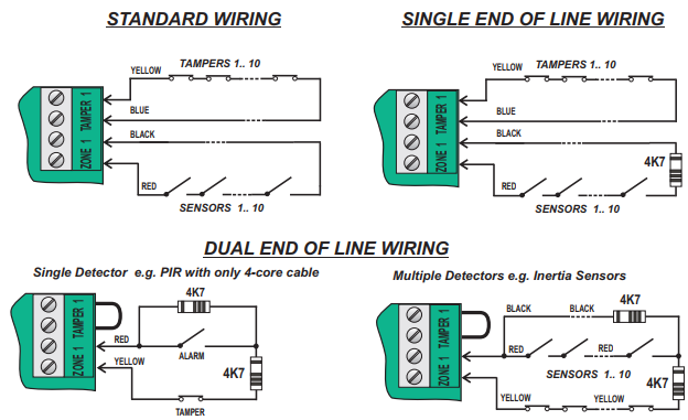
I have a brk smoke detectors throughout house and would like to trigger house alarm as it is connected to service that notifies me over the phone. I have looked online for information and stumbled on your video that looked similar to my needs but more so with Edward Cheung. Please advise where best to post this message as I think it may not be appropriate on mysensors.org.
Initially I was thinking of using brk relay but it is rated for 120V AC, I am based in europe with 240V AC, I do not need to power anything with AC and I want it to work when the power is down as both smoke detectors and house alarm operate on batteries.
I purchased the breadboard, 1k and 330 ohm resistors and 2 x PC817 4pin optocouplers without checking if my alarm is supporting normally open zones, it has normally closed options 4k7 resistor end of line and 2k2 resistor end of line and basic normally closed (breaking the circuit triggers alarm).
Alarm zone is a 5 v DC circuit.
Question:
Any advice on how to get output pins to stay constantly closed and change state when alarm is triggered, should I buy some other optocoupler with 6 pins that has ability to change output contacts when energized or any other approach?Thank you,
Oleg
Hello! It looks like you're interested in this conversation, but you don't have an account yet.
Getting fed up of having to scroll through the same posts each visit? When you register for an account, you'll always come back to exactly where you were before, and choose to be notified of new replies (either via email, or push notification). You'll also be able to save bookmarks and upvote posts to show your appreciation to other community members.
With your input, this post could be even better 💗
Register Login