Mother/Daughter board system
-
Well... the good news is my 3D board looks fantastic. The bad news is that I should have tested my schematic first. My wiring for using the input and output shift registers together is totally wrong. I'm going to have to move some things around and rewire it. There is a lesson here somewhere - I spent the last few days iterating on the board layout getting everything just the way I wanted because checking the schematic isn't as fun but it turns out I wasted a lot of time because it was wrong in the first place.
I need to decide if I'm going to switch my shift registers to using the SPI bus or stick with the a system that shares a clock and data pin and uses separate latch pins for each. It probably makes sense to move them to using the SPI bus - I wasn't sure this was a good idea because I didn't really understand it or how the radio and memory are using it. Now that I've read more about it, it seems like changing the registers to have their own select pins and using the SPI bus is probably the best way to go. Any thoughts on that?
-
So it turns out the "standard" input shift register that everyone uses in Arduino examples (SN74HC165) doesn't work on the SPI bus because it never puts MISO into high impedance. It can be fixed with another chip (single gate, 3 state chip). Instead, I found an input shift register that is designed to work on SPI (74HC589). I've got those on order now and will try it out on the breadboard before ordering any real boards.
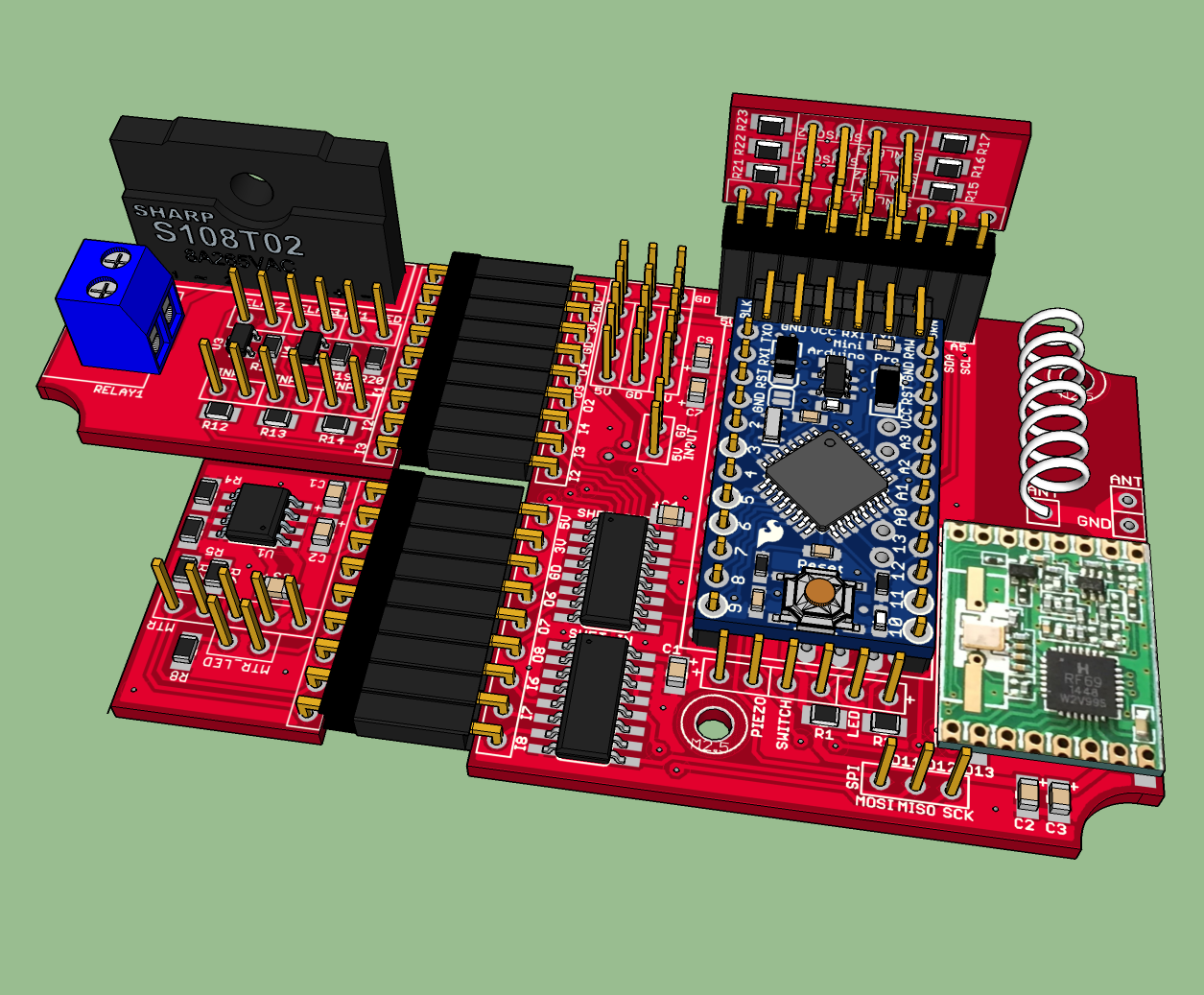
I've been having fun w/ EagleUp and SketchUp - here is a view of my main board with three daughter cards installed in it. The bare pins are the inputs and output jacks which will go to the external connectors (power, sensor jacks, valve controls, etc), LED's, and switches mounted in the case. I have to admin, seeing the resulting board in 3D is just extremely cool :) :)
-
Have you considerd the MYSX connector? It provides a common interface for MySensors boards (and others too for that matter). @tbowmo's new GW will have it, as does my board. @scalz have also made use of the design for his boards.
It is by no way ment as critizism of your solution, but I just wanted to mention it in case you missed it. -
Have you considerd the MYSX connector? It provides a common interface for MySensors boards (and others too for that matter). @tbowmo's new GW will have it, as does my board. @scalz have also made use of the design for his boards.
It is by no way ment as critizism of your solution, but I just wanted to mention it in case you missed it.@Anticimex said:
Have you considerd the MYSX connector?
Thanks - I did look at it and I think it's a great idea. But I decided it didn't match my needs for small modular boards that use the same pin outs for each board. I'm also trying to keep the design as flat as possible because of constraints on mounting it in the case along with lots of connectors.
-
@Anticimex said:
Have you considerd the MYSX connector?
Thanks - I did look at it and I think it's a great idea. But I decided it didn't match my needs for small modular boards that use the same pin outs for each board. I'm also trying to keep the design as flat as possible because of constraints on mounting it in the case along with lots of connectors.
@TD22057 ok, well, the MYSX connector comes in various versions for different needs, and the specification does not state that it is forbidden to use angular connectors (although not recommended for portable designs). But yes, even so, a DIL connector would stack up slightly more than a SIL connector would. On the other hand, it would provide a much more rigid connection. But that said, I do see your point, and MYSX is not for everyone :)
-
It wasn't so much the design, it's the fixed pin requirements (which I totally understand). I'm exposing 3 input and 3 output pins from shift registers on 2 of the expansion slots and a different set of Arduino pins on the 3rd expansion slots and none of those match up w/ the MYSX pin specifications.
-
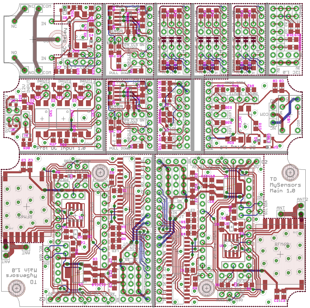
Update: I settled on an SPI based shift register system and received and tested those parts (they will require an update to the RFM69 library to use SPI transactions but we should do that anyway). I finished testing all of my schematics on a breadboard, fixed several errors, and submitted my PCB order this morning with Elecrow for 10 board of 10 cm x 10 cm. I was able to fit 2 main boards and 10 child boards on a single panel so that's 120 different boards for $25. I ended up creating the following 7 different child boards to use in the system:
- valve board (see first post)
- protected input board (see first post)
- sensor board (see first post)
- parking board (see first post)
- AC relay board (higher amperage/power relay for large loads)
- DC relay board (5V DC relay for small loads)
- I2C sensor board
Once I get the boards in and test them, I'll post the raw boards and schematics (or ping me if you want to see them now) in case anyone is interested. Just because it's cool, attached is an image of the final board submission.
-
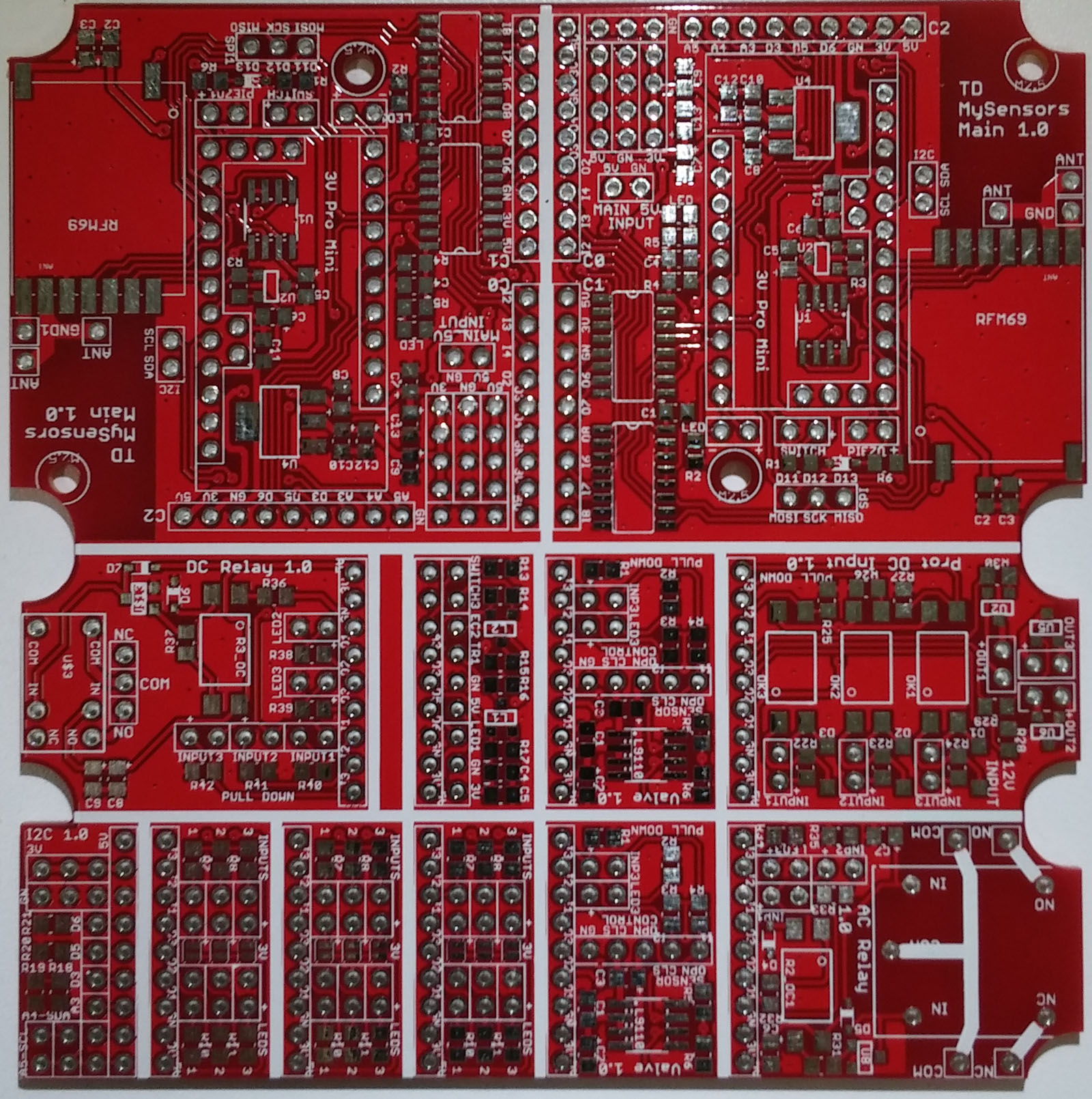
Yeah! Boards have arrived. I used elecrow.com and ordered 10 boards for $25. They shipped 14 and they arrived (California) in 16 days. Everything looks good so far. I probably should switch to a larger silk screen font for some of the labels but so far all the footprints seem to be correct. Next up is to start cutting the boards apart and start soldering...
-
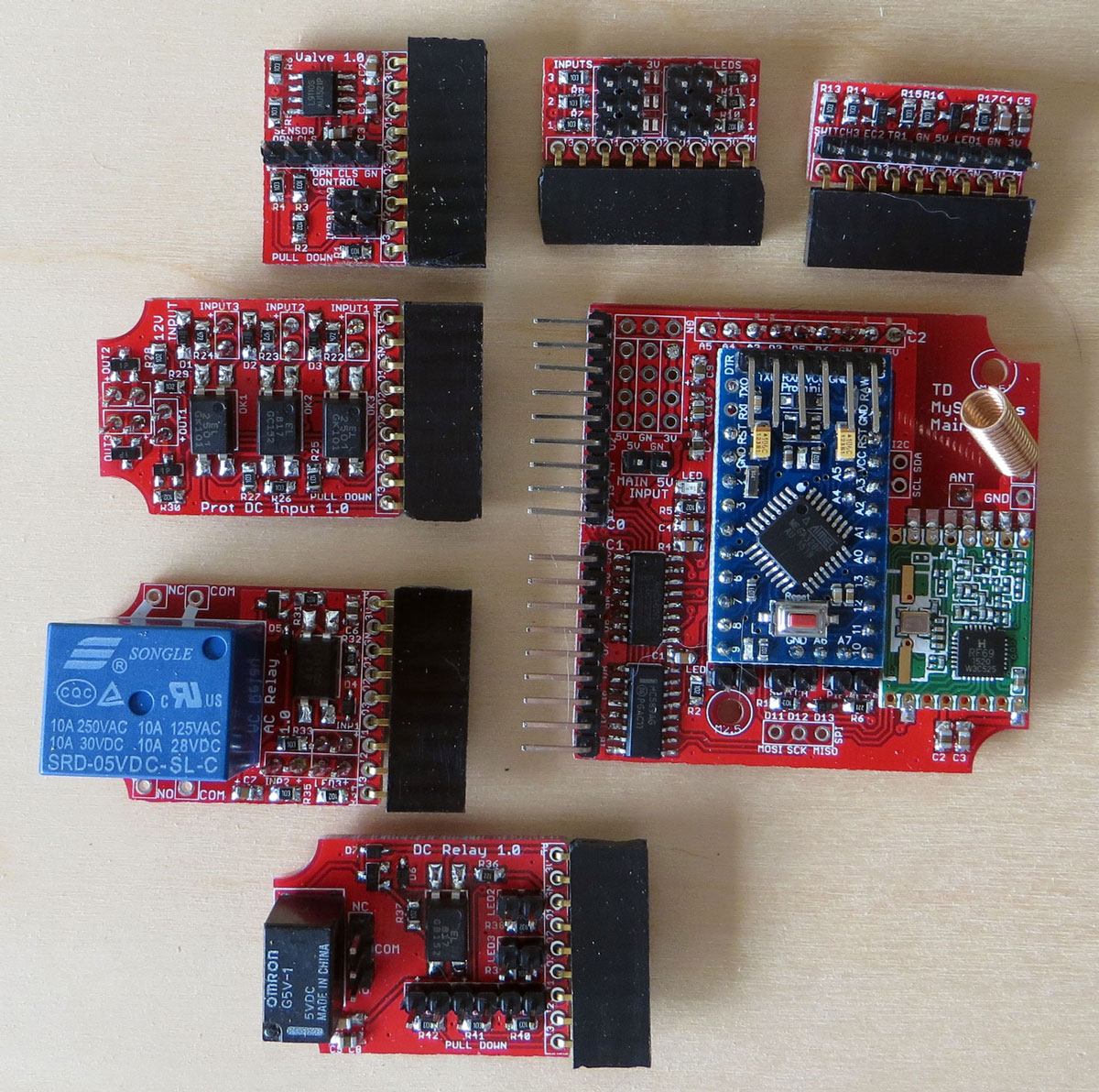
I've finished soldering the first batch of boards and things look pretty good so far. I had one diode footprint that was wrong but it was easy to fix and a couple of soldering errors that were also fixable. In hind sight, I think putting the power supply and other IC's under the arduino is a mistake - I should have moved them to the back of the board. If there is anything is wrong with a joint, it's impossible to get to for diagnosis and reworking. Here's a glamour shot of the mother and daughter boards:
-
I've finished soldering the first batch of boards and things look pretty good so far. I had one diode footprint that was wrong but it was easy to fix and a couple of soldering errors that were also fixable. In hind sight, I think putting the power supply and other IC's under the arduino is a mistake - I should have moved them to the back of the board. If there is anything is wrong with a joint, it's impossible to get to for diagnosis and reworking. Here's a glamour shot of the mother and daughter boards:
Surprisingly, all of my circuits are working perfectly. I found one relay label that was swapped (NO/NC) and one jumper pad that wasn't very useful but other than that, all of the functionality is working. I have to admit I'm quite surprised there wasn't some serious problem somewhere given that this is my first non-trivial board design.
When I started this design, I purchased a stereo microscope and it was fantastic. I'm no soldering expert by any measure but having the microscope (using the 5x lenses) made soldering all of the components very easy. After building 8 main boards and a bunch of daughter boards, I can now see why people invest in making a reflow oven for soldering.
I'll be uploading the design files and schematics as soon as I clean up the BOM. Next up is cleaning up the software to drive everything and start on the case construction.

-
FYI: Boards, schematics, BOM's, and software are now available here: https://github.com/TD22057/MySensors-Mother
-
Nice! Just a friendly reminder to read the CERN license how-to carefully and make sure you include all required files/documents for it or it won't be valid.
-
Nice! Just a friendly reminder to read the CERN license how-to carefully and make sure you include all required files/documents for it or it won't be valid.
@Anticimex Well that's kind of annoying. I supposed I'll go back and fix that. Do you happen to know if the github extraction for https://www.openhardware.io/ is working? I tried to use it but seems to just create a blank project.
-
You'll hate to press the blue "recycle" button next the github inputs. This import all the files in a unpublished state.
Further down on the page you can choose to publish all of them (">>") or drag the once you want to publish one-by-one.
Next time you fetch from github the published files will remain published.
Also, don't forget to press "Save" after changing published/unpublished state of images or design files.
-
It would be nice to have a .PDF of schematic, make it allot easier to view than to load a CAD program...
Thanks...
Hello! It looks like you're interested in this conversation, but you don't have an account yet.
Getting fed up of having to scroll through the same posts each visit? When you register for an account, you'll always come back to exactly where you were before, and choose to be notified of new replies (either via email, or push notification). You'll also be able to save bookmarks and upvote posts to show your appreciation to other community members.
With your input, this post could be even better 💗
Register Login