433mhz outlet
-
I am trying to convert this code for outlet ; http://forum.mysensors.org/topic/7/controlling-blinds-com-rf-dooya-motors-with-arduino-and-vera/10 (note its using old lib)
+vera doesn't give auto id (all other sensor like motion etc) so i made it int hey = 14; in this way i can get sketch name etc...
my 433 on code : 1101010101011100000000110
my 433 off code : 1101010101011100000011000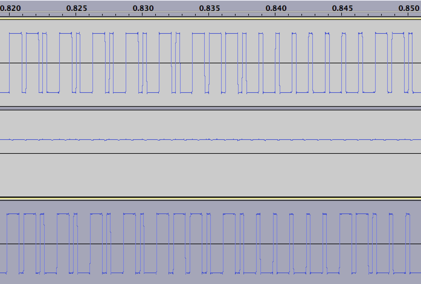
code txt : outlet433 -
I'm also interested in a working example to control some 240V Sockets http://www.wattsclever.com/products/easy-off-sockets
I've found the codes to send, just need to know how to send them :)
Below is a simple sketch I use for controlling 433Mhz outlets (sockets) with MySensors. I am not very good at coding but this sketch worked for my setup, I assume it could be improved.
https://codebender.cc/sketch:67827
I created a sensor node with a nano connected to a 433Mhz transmitter which is on mains power so the sensor is always "listening". I used the 5V from the nano to power the 433 transmitter but I believe it could run off 3.3V. The node controls four cheap 433Mhz outlets. I only have four but this sketch could be expanded to control many more. These outlets do not give feedback so the sketch is somewhat simple in that regard. These outlets use the PT2262 encoder which is common but may not work with your sockets. If you have a remote with your sockets, your can take it apart to see what encoder is used.
-Dwalt
Veralite UI5 :: IBoard Ethernet GW :: MyS 1.5
-
Below is a simple sketch I use for controlling 433Mhz outlets (sockets) with MySensors. I am not very good at coding but this sketch worked for my setup, I assume it could be improved.
https://codebender.cc/sketch:67827
I created a sensor node with a nano connected to a 433Mhz transmitter which is on mains power so the sensor is always "listening". I used the 5V from the nano to power the 433 transmitter but I believe it could run off 3.3V. The node controls four cheap 433Mhz outlets. I only have four but this sketch could be expanded to control many more. These outlets do not give feedback so the sketch is somewhat simple in that regard. These outlets use the PT2262 encoder which is common but may not work with your sockets. If you have a remote with your sockets, your can take it apart to see what encoder is used.
-Dwalt
Thank Dwalt, i have uploaded your sketch to one of my Nano's with a 433Mhz Transmitter and i can see it working. Ie using another Nano with a 433mhz receiver and the sample 433 receiver sketch i can see the various codes been received ie "419915".
My problem is i don't quite understand how to update your sketch with the codes for my sockets. Using my 433 receiver nano i can see my remote sends the code 501601 to turn on socket 1. I thought i would just need to convert this to Binary, but that doesn't seem to work.
Are you able to explain the code format for turning on/off sockets in your sketch ?
Joseph
-
Thank Dwalt, i have uploaded your sketch to one of my Nano's with a 433Mhz Transmitter and i can see it working. Ie using another Nano with a 433mhz receiver and the sample 433 receiver sketch i can see the various codes been received ie "419915".
My problem is i don't quite understand how to update your sketch with the codes for my sockets. Using my 433 receiver nano i can see my remote sends the code 501601 to turn on socket 1. I thought i would just need to convert this to Binary, but that doesn't seem to work.
Are you able to explain the code format for turning on/off sockets in your sketch ?
Joseph
@jribera How did you obtain your code (e.g."419915")? Did you use a library like RCSwitch or RemoteSwitch? If so, those libraries usually include sketches to retransmit the codes.
My sketch above is essentially a relay sketch which creates 4 child sensors in Vera. The children show up as 4 separate on-off light switches within "Devices". For my situation, I sniffed the code with the 433 receiver hooked up to a computer running Audacity and deciphered the signal into a binary sequence. For example -> remote button #1 -"ON" = 0101000101010101001111000, repeated 6 times. This is not necessarily the code the remote is using, it is a binary representation of what the pt2262 encoder sends through the air to the receiver, which decodes it through a pt2272.
The sketch mimics the timing and pattern of the signal by sending "highs" and "lows" of certain lengths at 433Mhz which arrive at the receiver looking similar to a signal sent from the programed remote. The sketch simply says put pin3 (the 433transmitter) to "high" then "delay" and then "low" to create the signal (static void ookPulse). The "pt2262Send" command determines whether the delay is long (500us) or short (160us) depending on whether the binary is a "1" or a "0" for each digit of the 'sniffed' binary code. The last digit is always a zero, so the pt2262send command repeats through a 16 digit code followed by an 8 digit code, adds the zero and then repeats the entire process 6 times. I should have used "uint32_t" instead of "uint16_t" and "uint8_t" for the 25digit codes. I was copying and pasting from different sources until it suddenly worked and then I didn't want to "fix" something that was working. I borrowed 'ookpulse' and 'pt2262send' from other sketches found online. I don't think it matters what they are named.
Within "Setup" in the sketch, the node is established as a repeater node and the number of child sensors (outlets) is declared. Within "Loop", the sensor node listens for incoming commands for that node and triggers different binary codes (to be processed by the pt2262send action) for each child and whether the command is off or on (incomingLightState -> 0 or 1).
Not the most elegant solution but it worked. I tried using some of the Libraries available from different sources and I could not get them to work with MySensors properly.
-Dwalt
-
Thanks Dwalt, understood now. I had assumed the code i received from the rc-switch sniffer sketch, could be translated to binary and used in your sketch.
Looks like i will need to build a different sniffer.
-
there is also a complete library RCSwitch to work with both transmitters and receivers
https://code.google.com/p/rc-switch/in my case I'm using a cheap wireless 433MHz motion sensor from my security system to drive the light too
-
@axillent Please can you share link of 433 motion sensor?
-
Finally managed to get this working by modifying Dwalts sketch to use the rcswitch library.
I found this much simpler to use as it allows you to learn your existing codes using a simple RF-Sniffer sketch (Sniffer.ino) ie no need to mess around with recording signals, binary codes etc. This sketch simply displays a decimal number which you can just send back to control your devices.
ie
define CODE_1On 0x5FF0DC //Sniffed code converted to Hex.
Serial.println("Turn on Socket 1");
mySwitch.send(CODE_1On, 24); // These codes are unique to each outlet
delay(50);With this working i can now safely control a number of 240V devices around the home !
-
Below is a simple sketch I use for controlling 433Mhz outlets (sockets) with MySensors. I am not very good at coding but this sketch worked for my setup, I assume it could be improved.
https://codebender.cc/sketch:67827
I created a sensor node with a nano connected to a 433Mhz transmitter which is on mains power so the sensor is always "listening". I used the 5V from the nano to power the 433 transmitter but I believe it could run off 3.3V. The node controls four cheap 433Mhz outlets. I only have four but this sketch could be expanded to control many more. These outlets do not give feedback so the sketch is somewhat simple in that regard. These outlets use the PT2262 encoder which is common but may not work with your sockets. If you have a remote with your sockets, your can take it apart to see what encoder is used.
-Dwalt
Nice job, I want one now!
Much easier to copy the transmission data with that sketch than the other examples here...
To help simplify your code, you can try to add in arrays...
int rfMessageON[4][2]=
{
  {0b0101000101010101, 0b00110011},
  {0b0101000101010101, 0b11000011},
  {0b0101000101010111, 0b00000011},
  {0b0101000101011101, 0b00000011}
};

int rfMessageOFF[4][2]=
{
  {0b0101000101010101, 0b00111100},
  {0b0101000101010101, 0b11001100},
  {0b0101000101010111, 0b00001100},
  {0b0101000101011101, 0b00001100}
};
to make a much simpler function...
void loop()
{
  gw.process();
}
//
void incomingMessage(const MyMessage &message)
{
  if (message.type==V_LIGHT)
  {
    Serial.print("Outlet #: ");
    Serial.println(message.sensor);
    Serial.print("Command: ");
    Serial.println(message.getBool());
    pt2262Send(message.getBool()? rfMessageON[message.sensor - 1][0],rfMessageON[message.sensor - 1][1]: rfMessageOFF[message.sensor - 1][0],rfMessageOFF[message.sensor - 1][1]);
  }
  delay(50);
}
(not tested)
-
@C.r.a.z.y. said:
@axillent Please can you share link of 433 motion sensor?
with pleasure
what exactly do you need?@axillent Motion sensor ; brand, model, which chip in it?
I have an remote like this (attached) and it didnt work with RC-Switch. (RC-Switch works with SC5262 / SC5272, HX2262 / HX2272, PT2262 / PT2272, EV1527, RT1527, FP1527 or HS1527 chipsets)
If my remote is working with other chipset, how can i read and transmit it?
How can i find this remote's chipset?
----PIC16F630 ---update http://ww1.microchip.com/downloads/en/devicedoc/40039f.pdf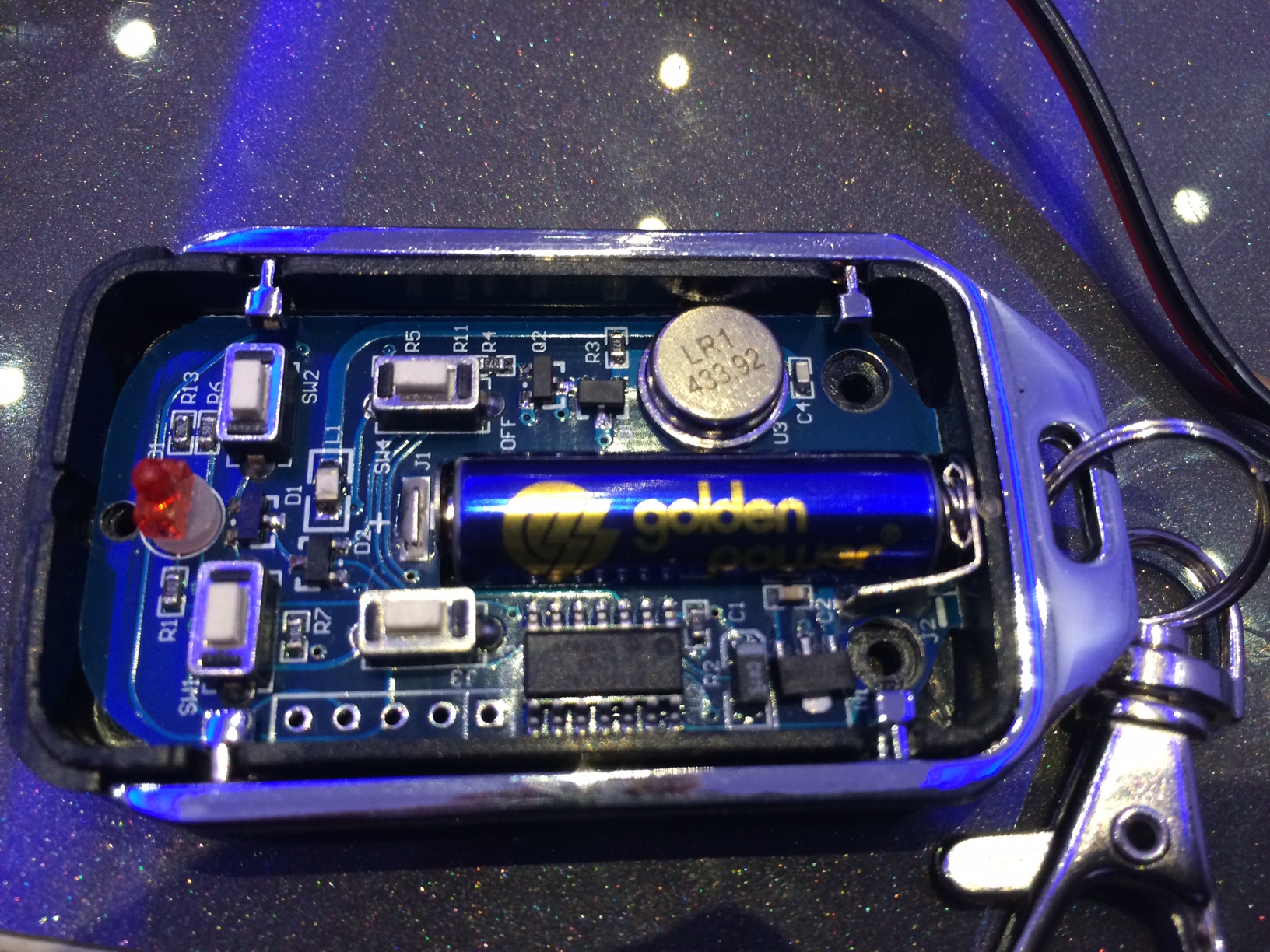
-
Finally managed to get this working by modifying Dwalts sketch to use the rcswitch library.
I found this much simpler to use as it allows you to learn your existing codes using a simple RF-Sniffer sketch (Sniffer.ino) ie no need to mess around with recording signals, binary codes etc. This sketch simply displays a decimal number which you can just send back to control your devices.
ie
define CODE_1On 0x5FF0DC //Sniffed code converted to Hex.
Serial.println("Turn on Socket 1");
mySwitch.send(CODE_1On, 24); // These codes are unique to each outlet
delay(50);With this working i can now safely control a number of 240V devices around the home !
-
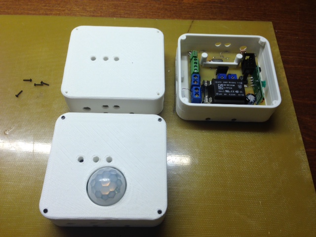
@C.r.a.z.y. my sensors are none brand)) all using PT2262
was purchased from here http://ru.aliexpress.com/item/-/1953282784.html?recommendVersion=1
I have PIR sensors, door sensors, water leakage and gas leakage sensors.
I also have a remote similar to your.Remote is easily recognized using radio 433MHz receiver connected to arduino and RCSwitch library
It is also a plan to create a gateway from 433MHZ to NRF24 network - this can help me to build vera3 automation using a security sensors without purchasing z-wave or building mysensors sensors
-
@C.r.a.z.y. my sensors are none brand)) all using PT2262
was purchased from here http://ru.aliexpress.com/item/-/1953282784.html?recommendVersion=1
I have PIR sensors, door sensors, water leakage and gas leakage sensors.
I also have a remote similar to your.Remote is easily recognized using radio 433MHz receiver connected to arduino and RCSwitch library
It is also a plan to create a gateway from 433MHZ to NRF24 network - this can help me to build vera3 automation using a security sensors without purchasing z-wave or building mysensors sensors
@axillent Thank you. Do you have dip switches in your sensors?
I found a comparasion table maybe this could help people like me;
If my remote is not a fixed code, how can i read and transmit it?
-
@C.r.a.z.y. some sensors do have dip switches, some have preprogrammed radio code
if you have RF receiver you can try to get a code from your remote using example receiver sketch from RCSwitch library. I build a custom arduino with RF receiver and a button which I use to program the first received code into arduino EEPROM. Later this code is used to identify which sensor should light up my leds.
-
@axillent OK i understand fixed codes are fine with RCSwitch.
How can i transmit this data ?
1100 0011 0010 0010 0011 0000 1100 1000 1000
1100 0011 0001 0010 0011 0000 1100 0100 1000@C.r.a.z.y. Open any transmitting example from RCSwitch
I never did it but I think send() function is designed for this
https://code.google.com/p/rc-switch/wiki/HowTo_Send?tm=6