Killing Nanos, one after the other
-
Happy New Year everybody!
First post, so please bear with me.
I have got five Arduino Nanos with FTDI chip (far east replicas). When connected one to my PC (Ubuntu 20.04) they are immediately detected as valid and working USB devices:
lsusb
ID 0403:6001 Future Technology Devices International, Ltd FT232 Serial (UART) IC

dmesg | grep ttyUSB
FTDI USB Serial Device converter now attached to ttyUSB0
Using the Arduino IDE 2:1.0.5+dfsg2-4.1 I even could flash sketches successfully. No problem, whatsoever.
BUT: as soon as I put the Nano onto a breadboard, set up my circuit (two DS18B20 one 4.7k Resistor and 8 wires) and connect it to the PC to flash it, it's dead. After taking it off from the breadboard it's no longer detected as USB device. Plugging it out and back in does not help. It is no more, it has ceased to be, it is an ex-Nano - so it seems at least.
I have read about missing bootloaders and flashing through another Nano's ICSP interface. But even if this was possible, hadn't the nano then at least to be seen by the PC? Is the bootloader a prerequisite for the FTDI to work and make itself detected?
Already killed two, three to go.
Is there a way to bring these dead Nanos back to life?
Any help is very much appreciated.
Thank you.
3nibble
-
Bootloader is not the problem, you should see the Ftdi Serial device even without a MCU connected.
Did you connect any power supply to the breadboard? Maybe you reversed the polarity?
It would help if you could post a schematic of the circuit and a photo with the actual circuit. -
-
Thanks for your replies.
Just killed another one.
Compiled the sketch, flashed a naked Nano that connected to my PC without any problem.
The Arduino IDE said "Sketch flashed successfully". The Nano showed a green LED blinking.
I pulled the Nano off of the PC and put it on the breadboard as shown in the pictures below. Reconnecting it to the PC just proved I had killed the third one. No signs of life - nothing.@r-nox
I am on Linux@alexelite
This is my breadboard setup:
![[01].JPG](/assets/uploads/files/1609675621815-01.jpg)
![[02].JPG](/assets/uploads/files/1609675621820-02.jpg)
![[03].JPG](/assets/uploads/files/1609675621814-03.jpg)
![[04].JPG](/assets/uploads/files/1609675621817-04.jpg)
This is my code:
I took it from here
https://www.arduino-projekte.de/index.php?n=64
and only changed the data bus pin from 10 to 3.#include <OneWire.h> // OneWire DS18S20, DS18B20, DS1822 Temperature Example // // http://www.pjrc.com/teensy/td_libs_OneWire.html // // The DallasTemperature library can do all this work for you! // http://milesburton.com/Dallas_Temperature_Control_Library OneWire ds(3); // on pin 3 void setup(void) { Serial.begin(9600); } void loop(void) { byte i; byte present = 0; byte type_s; byte data[12]; byte addr[8]; float celsius, fahrenheit; if ( !ds.search(addr)) { Serial.println("No more addresses."); Serial.println(); ds.reset_search(); delay(250); return; } Serial.print("ROM ="); for( i = 0; i < 8; i++) { Serial.write(' '); Serial.print(addr[i], HEX); } if (OneWire::crc8(addr, 7) != addr[7]) { Serial.println("CRC is not valid!"); return; } Serial.println(); // the first ROM byte indicates which chip switch (addr[0]) { case 0x10: Serial.println(" Chip = DS18S20"); // or old DS1820 type_s = 1; break; case 0x28: Serial.println(" Chip = DS18B20"); type_s = 0; break; case 0x22: Serial.println(" Chip = DS1822"); type_s = 0; break; default: Serial.println("Device is not a DS18x20 family device."); return; } ds.reset(); ds.select(addr); ds.write(0x44,1); // start conversion, with parasite power on at the end delay(1000); // maybe 750ms is enough, maybe not // we might do a ds.depower() here, but the reset will take care of it. present = ds.reset(); ds.select(addr); ds.write(0xBE); // Read Scratchpad Serial.print(" Data = "); Serial.print(present,HEX); Serial.print(" "); for ( i = 0; i < 9; i++) { // we need 9 bytes data[i] = ds.read(); Serial.print(data[i], HEX); Serial.print(" "); } Serial.print(" CRC="); Serial.print(OneWire::crc8(data, 8), HEX); Serial.println(); // convert the data to actual temperature unsigned int raw = (data[1] << 8) | data[0]; if (type_s) { raw = raw << 3; // 9 bit resolution default if (data[7] == 0x10) { // count remain gives full 12 bit resolution raw = (raw & 0xFFF0) + 12 - data[6]; } } else { byte cfg = (data[4] & 0x60); if (cfg == 0x00) raw = raw << 3; // 9 bit resolution, 93.75 ms else if (cfg == 0x20) raw = raw << 2; // 10 bit res, 187.5 ms else if (cfg == 0x40) raw = raw << 1; // 11 bit res, 375 ms // default is 12 bit resolution, 750 ms conversion time } celsius = (float)raw / 16.0; fahrenheit = celsius * 1.8 + 32.0; Serial.print(" Temperature = "); Serial.print(celsius); Serial.print(" Celsius, "); Serial.print(fahrenheit); Serial.println(" Fahrenheit"); }Any ideas?
Thank you.
-
EDIT:
Found my mistake. I just had a false understanding of the breadboard's rails by thinking of them as individually isolated groups of 5 pads. Now all is well.
![[01]_v1.JPG](/assets/uploads/files/1609683254387-01-_v1.jpg)
Interestingly, the current Nano survived the abuse.
So back to question No 1: is there a way to rescue the apparently dead Nanos?Thanks.
-
EDIT:
Found my mistake. I just had a false understanding of the breadboard's rails by thinking of them as individually isolated groups of 5 pads. Now all is well.
Interestingly, the current Nano survived the abuse.
So back to question No 1: is there a way to rescue the apparently dead Nanos?Thanks.
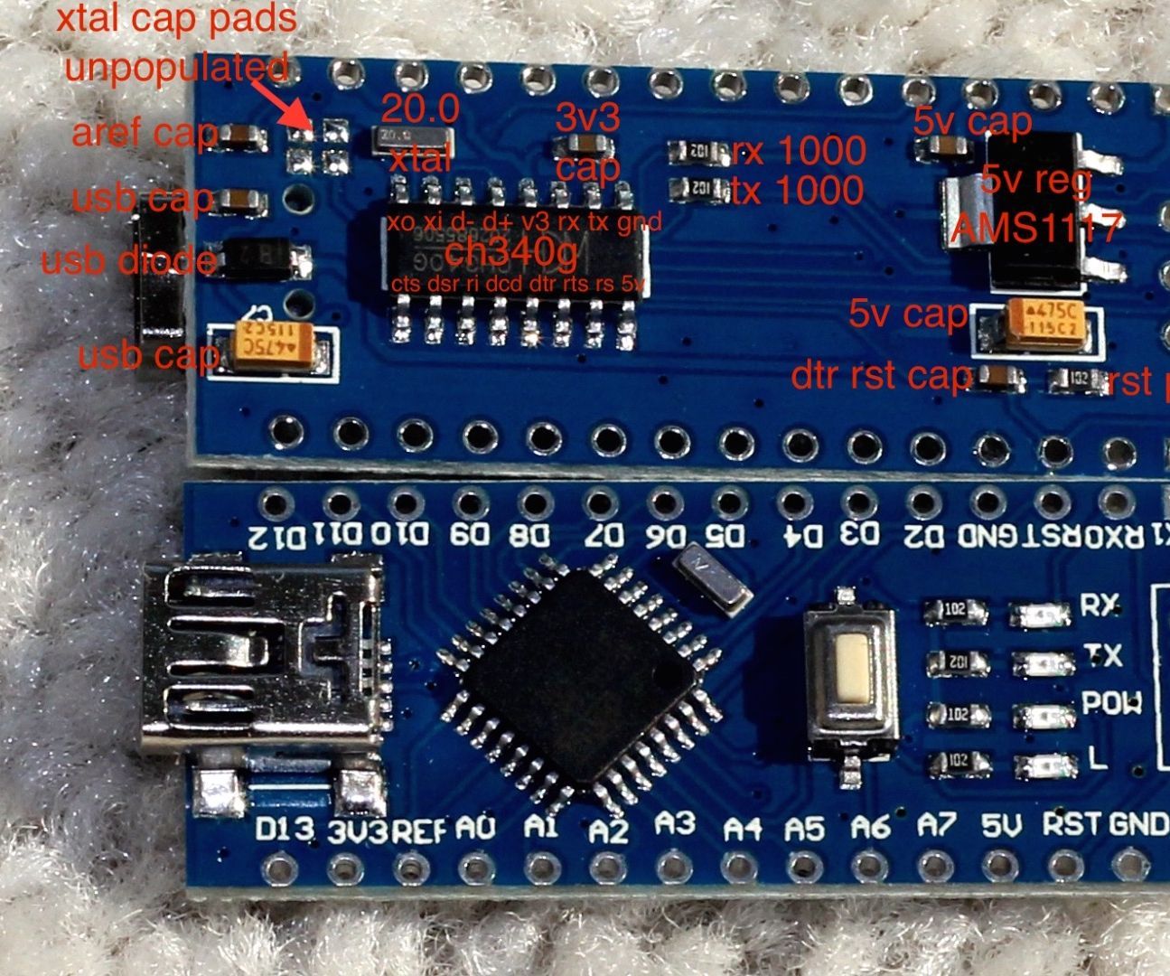
@3nibble You shorted the power supply. This will not kill your MCU or usb-serial chip. The 5V rail is the USB power rail and usually if you short it, the USB controller disconnects power or limits current to that USB port until the short is removed or it need a reset.
If one board works and another one doesn't you might have a blown fuse on the backside of the board. Pease post a photo with the backside.
The schematic I found shows a Schottky Diode between VUSB and +5V. It might be open circuit because of your short. If you have a DC 6V-12V power supply you can try powering the board through VIN pin.
Or you can short the usb diode with some conductive tweezers.
-
@alexelite said in Killing Nanos, one after the other:
You shorted the power supply. This will not kill your MCU or usb-serial chip.
Well, I hope, you are right.
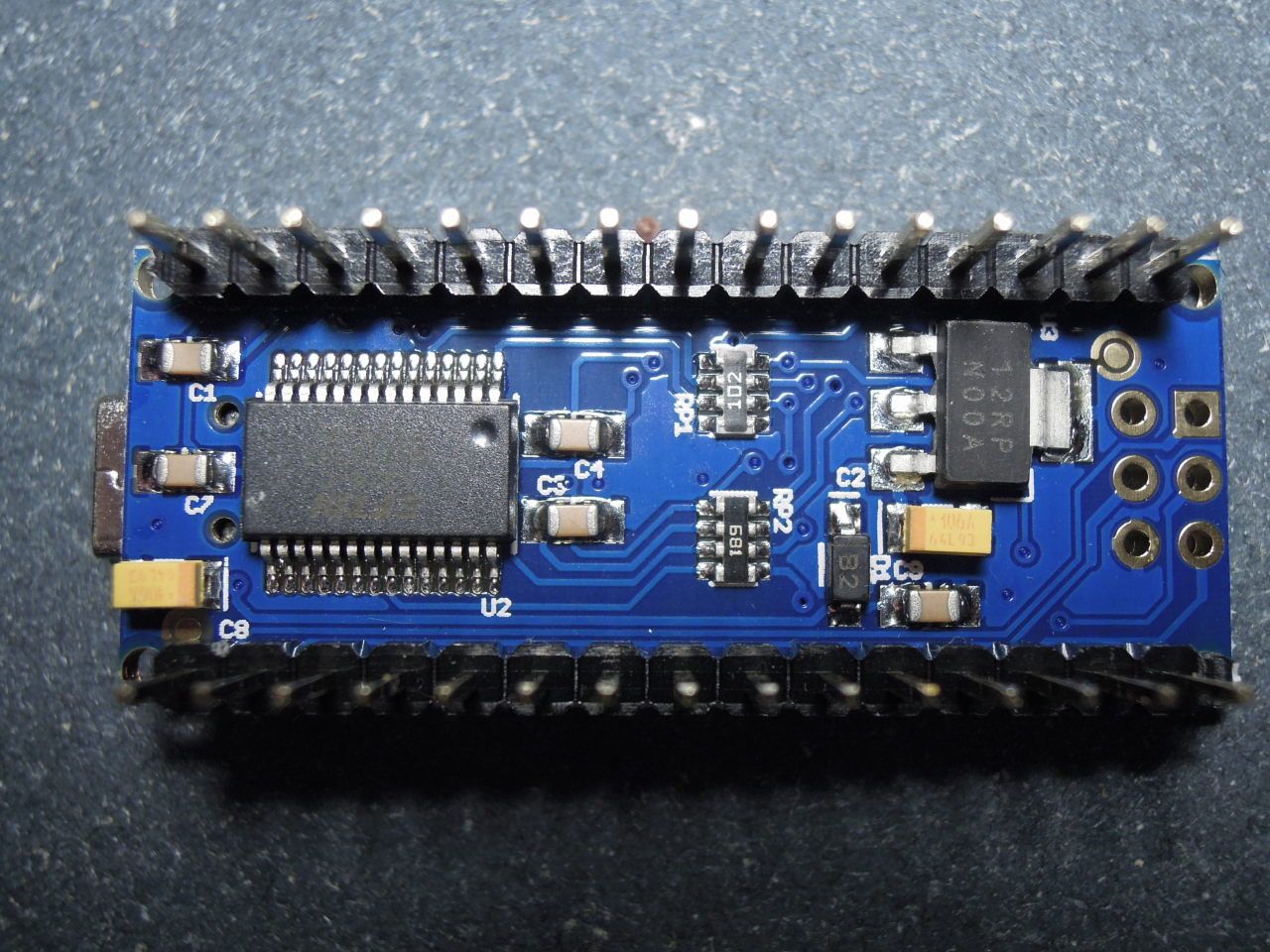
Here are the pictures.
DeadNanoNo1
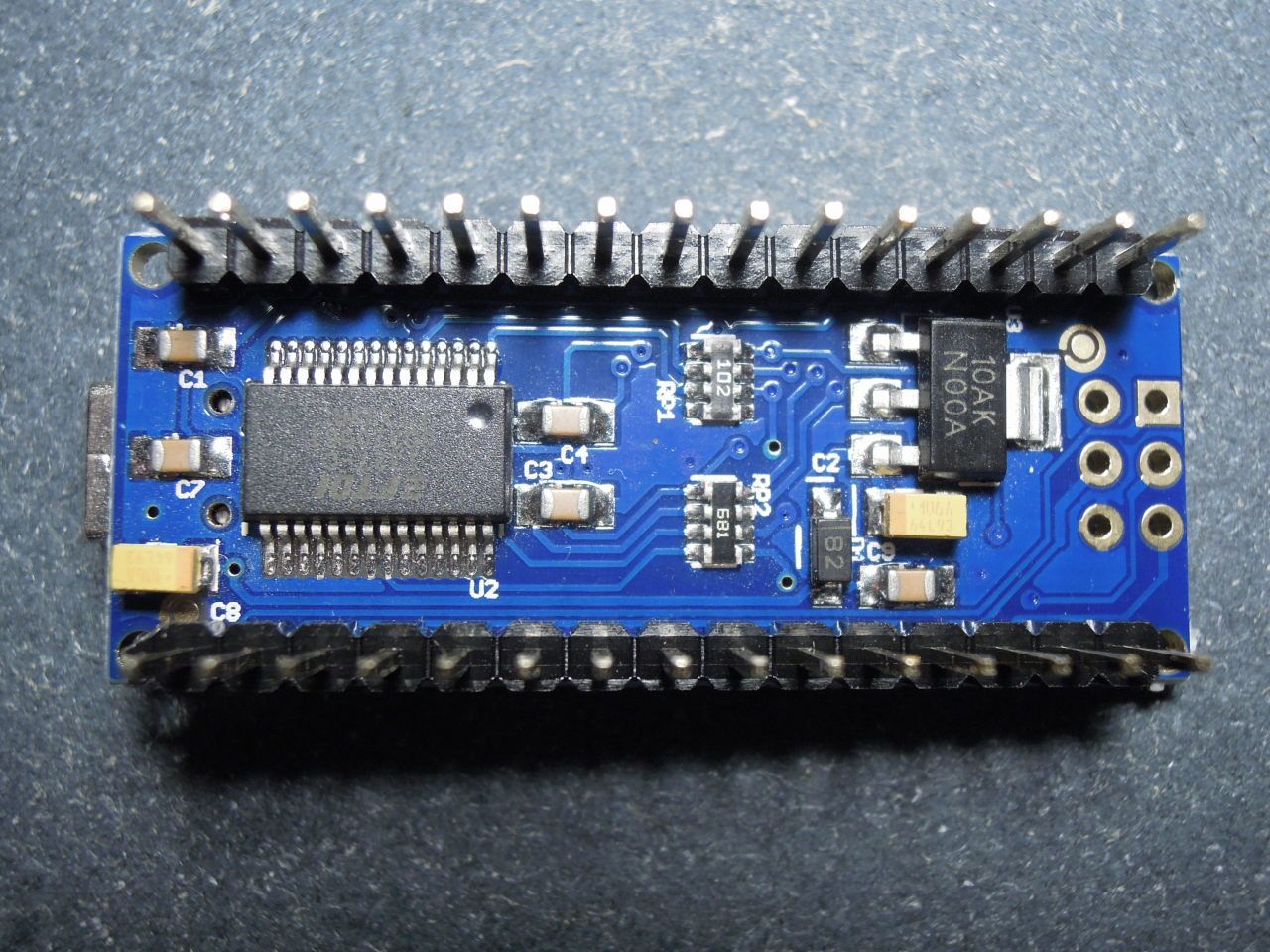
DeadNanoNo2
Thanks,
-
@alexelite said in Killing Nanos, one after the other:
You shorted the power supply. This will not kill your MCU or usb-serial chip.
Well, I hope, you are right.
Here are the pictures.
DeadNanoNo1
DeadNanoNo2
Thanks,
-
@alexelite said in Killing Nanos, one after the other:
Do you have a digital multimeter (DMM)? You can measure the voltage between gnd and both lead of the diode.
Yes, I have one. For both MPs I got
GND vs the "B-side" of "B2" 0.0V
GND vs the "2-side" of "B2" 4.97VThe Diode-Test-Function shows .0L in one direction and 1.9 running down fast to .0L in the opposite direction.
Does this tell us the diodes do their job?
Regards shortening the diode, I am not sure whether I have means or the ability to solder on a bridge across this tiny part.
Kind regards,
Hello! It looks like you're interested in this conversation, but you don't have an account yet.
Getting fed up of having to scroll through the same posts each visit? When you register for an account, you'll always come back to exactly where you were before, and choose to be notified of new replies (either via email, or push notification). You'll also be able to save bookmarks and upvote posts to show your appreciation to other community members.
With your input, this post could be even better 💗
Register Login