Safe AC dimmer with code
-
All
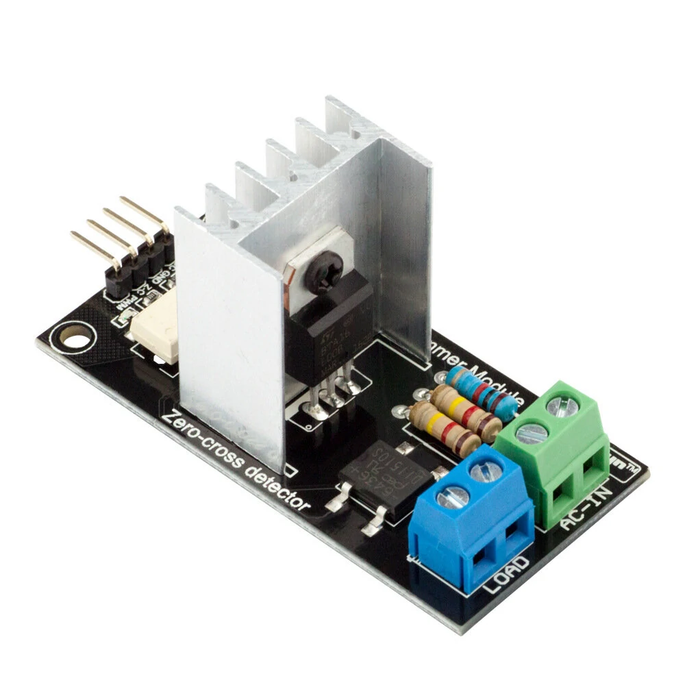
Has anyone found a safe and reliable dimmer code to with with an AC dimmer? I have been racking my brains and cant find a good working code. I'm using commercially made pwm/zero cross dimmers from RobotDYN(see picture). I can get a 12 volt version working but have been unsuccessful in getting this to work. Disclaimer - Im a hardware guy not a code guy.
My end goal would be to get it working with the rotary encoder. This is the RAW pwm/zero crossing code.
#include "hw_timer.h"
#include <Time.h>
#include <TimeLib.h>
#include <TimeAlarms.h>

//Pin Setups
const int zcPin = 12; //zero-cross detection pin D6
const int pwmPin = 13;  //pwm pin - fires the triac D7

//Dimmer Settings including fades.
byte fade = 1;
byte state = 1;
byte tarBrightness = 255; //"target" brightness - going to have go convert this to a precentage for OH
byte curBrightness = 0; //current brightness level
byte zcState = 0; // 0 = ready; 1 = processing;

char lvl[50];

void setup() {
  Serial.begin(115200); //Sets the data rate in bits per second (baud) for serial data transmission.

  //Dimmer pins -set up the pwm and zero cross pins
  pinMode(zcPin, INPUT_PULLUP);
  pinMode(pwmPin, OUTPUT);
  attachInterrupt(zcPin, zcDetectISR, RISING);    // Attach an Interupt to Pin 2 (interupt 0) for Zero Cross Detection
  hw_timer_init(NMI_SOURCE, 0);
  hw_timer_set_func(dimTimerISR);

 } // END SETUP

void dimTimerISR() {
  if (fade == 1) {
    if (curBrightness > tarBrightness || (state == 0 && curBrightness > 0)) {
      --curBrightness;
    }
    else if (curBrightness < tarBrightness && state == 1 && curBrightness < 255) {
      ++curBrightness;
    }
  }
  else {
    if (state == 1) {
      curBrightness = tarBrightness;
    }
    else {
      curBrightness = 0;
    }
  }

  if (curBrightness == 0) {
    state = 0;
    digitalWrite(pwmPin, 0);
  }
  else if (curBrightness == 255) {
    state = 1;
    digitalWrite(pwmPin, 1);
  }
  else {
    digitalWrite(pwmPin, 1);
  }

  zcState = 0;
}

void zcDetectISR() {
  if (zcState == 0) {
    zcState = 1;

    if (curBrightness < 255 && curBrightness > 0) {
      digitalWrite(pwmPin, 0);

      int dimDelay = 30 * (255 - curBrightness) + 400;//400
      hw_timer_arm(dimDelay);
    }
  }
}
Can anyone help?
-
@Dbagioni said in Safe AC dimmer with code:
zcPin
Which pin do you use? The comments say something else (twice) than the code.
Which CPU do you use?
For many Arduinos, you can only use pin 2 and 3. -
The code I posted is the raw code for the zero-cross dimmer. When I had tried to merge the "dimmer with rotary encoder" sketch and the zero-cross code I had wired it up with the ZC pin as 2 and the PWM pin on 3. Encoder was wired: SW pin on 4, CLK pin on 5 and CE pin on 6. 7/8/A2 were used for status LED's.
I was running it with an older NANO with the 328.
Hello! It looks like you're interested in this conversation, but you don't have an account yet.
Getting fed up of having to scroll through the same posts each visit? When you register for an account, you'll always come back to exactly where you were before, and choose to be notified of new replies (either via email, or push notification). You'll also be able to save bookmarks and upvote posts to show your appreciation to other community members.
With your input, this post could be even better 💗
Register Login