'MySensoring' a FlashForge Creator Pro 3D Printer.
-
Most here have seen me whine about wanting a 3D printer, well those days are gone. I got a FlashForge Creator Pro, which after making some repairs due to shipping damage, works quite well, at least with my test prints...
That said, one very annoying issue with the printer is that the on/off switch is located in the back, which makes it a bit of a pain to get to. So I thought, I should "MySensor" this puppy.... :-)
So before I really get into printing off really "useful stuff", I wanted to place a small HD camera inside the printer, and allow for remote and local power on/off and viewing.
I did all this kinda fast so the workmanship isn't up to my desire level, but......
Parts:
- Wire
- Push Button
- Mini Rboard and Radio
- HD Camera and 2.5mm Lens
Highlights:
- Main power switch is still the Master On/Off. (I can leave it on now)
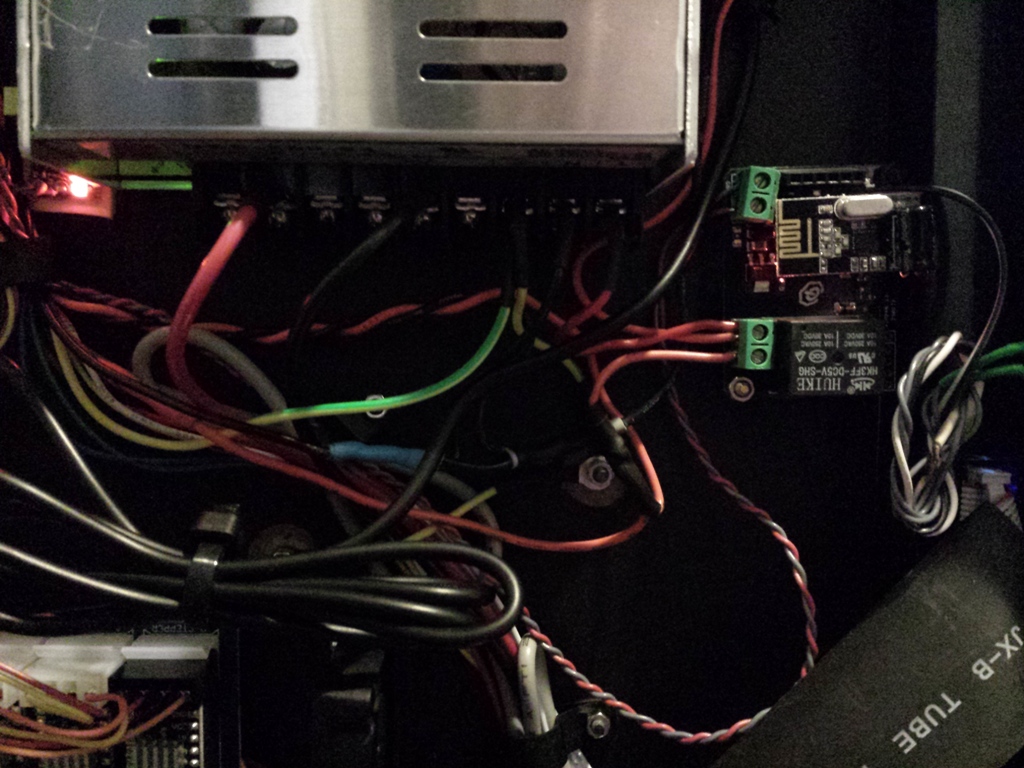
- The Printers power supply is fairly robust, so I didn't want to switch the 24vdc output to all the electronics (not too mention that leaves the PSU powered up all the time, and I didn't want that either). So I decided it would be best to switch the mains power to the PSU.
- I Branched off the mains with a small 120vac to 5vdc transformer to power the Mini Rboard.
- I mounted the camera's 12v 2a transformer inside the printers electronic compartment also. (the camera will only run if the unit is powered up)
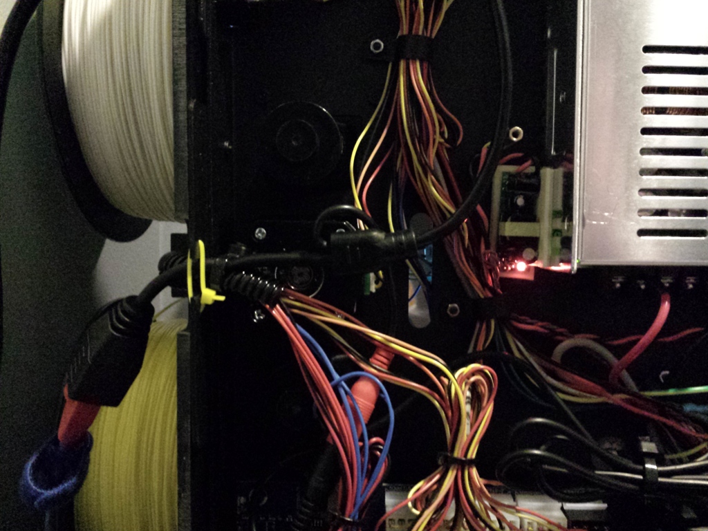
I mounted the camera in on the back wall ( I will probably change this as I'm not satisfied with the viewing angle) and ran the line down through the left rear wire chase. Once inside the electrical compartment, I fed the Ethernet line out the back with the extruder cables and left the power line for the camera inside the electrical compartment.
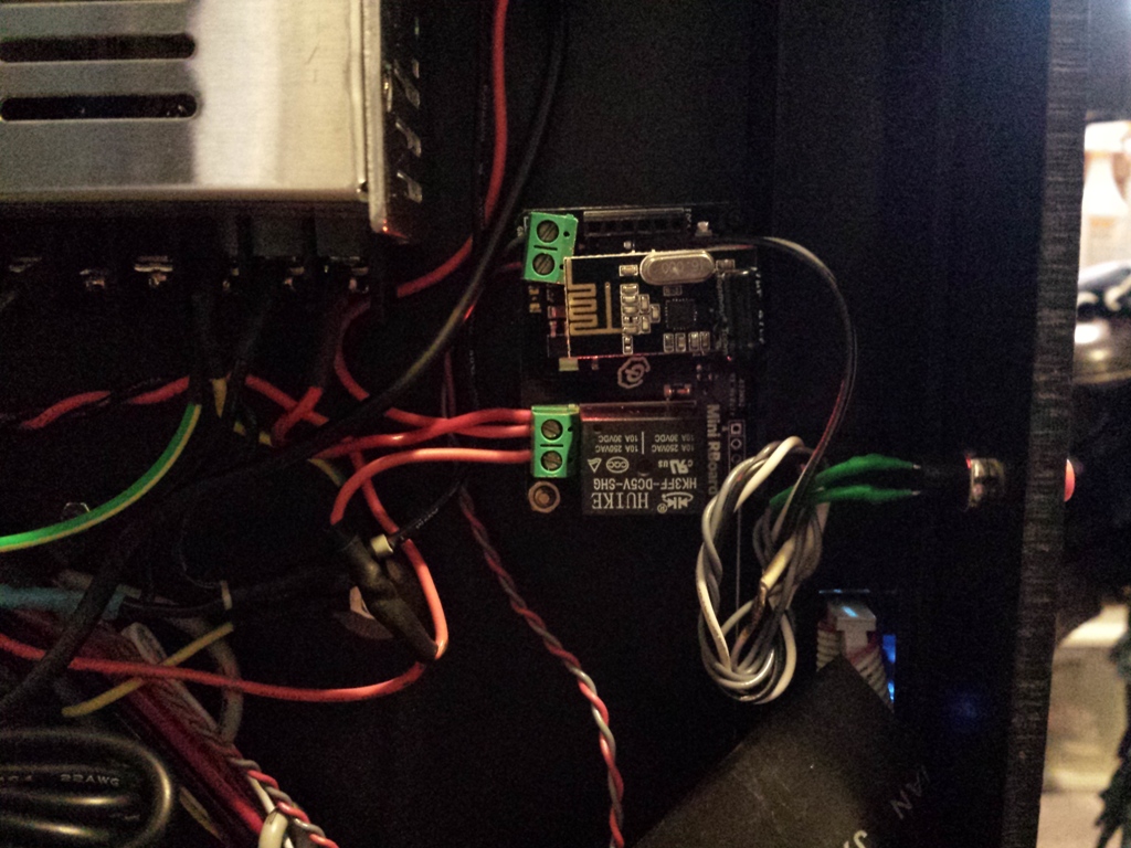
I drilled a small hole underneath the control display in the middle, mounted the Rboard off a platform screw that was already present.
I mounted the power transformer for the Rboard with supper sticky double sided tape and also zip tied the wiring to a post. (I really should print an encloser for it but.....)
I also mounted the cameras power supply in the same manor.
From there it's just a matter of breaking down the wiring to the printers PSU and switching that and power to the camera....
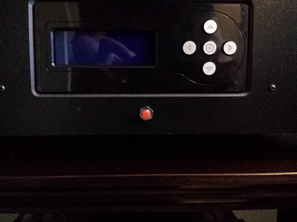
The push button is connected to the A0 jumper set on the Rboard, and the only change in the standard relay with push button sketch was to change pin 3 to 14 (is the digital mapping to A0)
Sorry about the quality of the pictures...
-
Ha, you are doing exactly what I have in my for my FABtotum(s).
Including a camera :) -
Ha, you are doing exactly what I have in my for my FABtotum(s).
Including a camera :)@marceltrapman FABtotum**(s)** as in more then 1? Nice...
-
@marceltrapman FABtotum**(s)** as in more then 1? Nice...
@ServiceXp said:
@marceltrapman FABtotum**(s)** as in more then 1? Nice...
That is exactly it :)
Right now it is 1.
#2 is waiting for 50 units before me.
Hello! It looks like you're interested in this conversation, but you don't have an account yet.
Getting fed up of having to scroll through the same posts each visit? When you register for an account, you'll always come back to exactly where you were before, and choose to be notified of new replies (either via email, or push notification). You'll also be able to save bookmarks and upvote posts to show your appreciation to other community members.
With your input, this post could be even better 💗
Register Login