Low Power: How much current? [Solved]
-
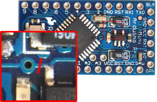
@brolly759 Is your design finished or still evolving? Are you planning to say how you did it in exacting detail, or just in general terms? At the moment I see your results (above), but at the moment I'm not sure exactly what you did, other than it involved starting with a Pro Mini, removing the Power LED, removing the power regulator, and invoking a sleep cycle. Is the following the best summation to date? http://forum.arduino.cc/index.php?topic=341958.0 If so, please let me know, and I'll give it a more careful read. On the other hand, if something else is a better summation, please let me know what that is, and I'll add it instead to the round-up.
Yesterday I placed an order with Great Wall Electronics for 10 Arduino Pro Mini's. That may take anywhere from two to four weeks to arrive. Meanwhile, I should receive the three red Pro Mini's from Amazon (above) tomorrow. With those I plan to start with the same three steps as before and then see how the measurement numbers look. If promising, I guess I'll next proceed based on what I find in the links you and scalz provided:
http://forum.arduino.cc/index.php?topic=341958.0
http://www.gammon.com.au/power
hallard.me
jeenode
lowpowerlaband see where that gets me. At the moment, those are the only guides I have that are reasonably detailed. If in addition anything else should be on that list, please let me know.
-
@NeverDie I will rewrite everything up again. The numbers I posted about was me just unplugging wires and seeing what my current draw was.... haha the link is where my dual post is located where I am talking to Gammon about this problem :)
@everyone So Gammon said this about our problem:
"I am guessing you are parasitically powering the NRF. Before sleeping make sure you set the connections to it to high-impedance. For example, SPI.end() followed by making sure the SPI (and other two) pins are inputs (or maybe outputs and LOW). For example, a snippet from my code with that gadget:"
 bool ok = radio.write (&reading, sizeof reading);
  radio.startListening ();
  radio.powerDown ();
  SPI.end ();
  // set pins to OUTPUT and LOW
  for (byte i = 9; i <= 13; i++)
    {
    pinMode (i, OUTPUT);
    digitalWrite (i, LOW);
    }  // end of for loop
  ADCSRA = 0;  // disable ADC
  power_all_disable();
I am looking in the library to see if we do SPI.end() before sleep but cant find anything...
-
yes. Gammon is right. I needed to do pinmode output=0 when I tested. I didn't do the spi.end but I think is good thing to do.
@Neverdie: I hope and am sure you will get it!
in the mean time I am redesigning my board with some feedbacks you gave me. thx.
it will be 0805/atmel solderable version, no mini pro. and will be 5cmx2.3. same specs as I did on my other board. so far so good but now 4layer. only for rfm for the moment. can't do magie. but two boards on a 5cmx5cm. not expensive at elecrow... I hope I will get it finished for this week... -
great I'm happy for you.
-
Okay, so originally I was getting 2.7-2.9uA with Arduino/NRF. Stock MySensors library and Arduino 1.0.6 IDE. ( I am using the BinarySwitchSleep Sketch from MySensors lib)
To get even lower power.... If you open up mysensors.cpp the sleep function is there. For the BinarySwitchSleep sketch you are looking for this sleep function as there are a few:
You want to add this:
SPI.end();
	for (byte i = 9; i <= 13; i++)
    {
    pinMode (i, OUTPUT);
    digitalWrite (i, LOW);
    }  // end of for loop
to this:
bool MySensor::sleep(uint8_t interrupt, uint8_t mode, unsigned long ms) {
	// Let serial prints finish (debug, log etc)
	bool pinTriggeredWakeup = true;
	Serial.flush();
	RF24::powerDown();
	attachInterrupt(interrupt, wakeUp, mode);
	if (ms>0) {
		pinIntTrigger = 0;
		sleep(ms);
		if (0 == pinIntTrigger) {
			pinTriggeredWakeup = false;
		}
	} else {
		Serial.flush();
		LowPower.powerDown(SLEEP_FOREVER, ADC_OFF, BOD_OFF);
	}
	detachInterrupt(interrupt);
	return pinTriggeredWakeup;
}
and it will look like this:
bool MySensor::sleep(uint8_t interrupt, uint8_t mode, unsigned long ms) {
	// Let serial prints finish (debug, log etc)
	bool pinTriggeredWakeup = true;
	Serial.flush();
	RF24::powerDown();
	attachInterrupt(interrupt, wakeUp, mode);

	SPI.end();

	for (byte i = 9; i <= 13; i++)
    {
    pinMode (i, OUTPUT);
    digitalWrite (i, LOW);
    }  // end of for loop

	if (ms>0) {
		pinIntTrigger = 0;
		sleep(ms);
		if (0 == pinIntTrigger) {
			pinTriggeredWakeup = false;
		}
	} else {
		Serial.flush();
		LowPower.powerDown(SLEEP_FOREVER, ADC_OFF, BOD_OFF);
	}
	detachInterrupt(interrupt);
	return pinTriggeredWakeup;
}
Because you are shutting off and turning all pins low, you will need to add this to the beginning of your program loop to reinitialize the NRF:
void loop()
{
  sensor_node.begin();
If you add just the SPI.end(); your current will be 2uA.
If you add both SPI.end(); and LOW pin loop, your current will be 1.5uA -
Some more facts here:
If you ONLY do the for/loop to shut off PIN9-13 in the sleep function and do NOT shut off SPI... you do NOT need to reinitialize the radio on wake-up.
The current draw for For/Loop LOW w/o shutting off SPI is 2.1uA-2.2uA.
This is a good and bad. If you have a sensor that is going to be switched on and off a lot, the re initialization time is noticeable on a fluke meter. You can see it staying high much longer. So, if someone knows how long it takes to initialize, then we can determine if shutting off SPI is worth it. ~600nA savings vs high reconnect time.
-
Some more facts here:
If you ONLY do the for/loop to shut off PIN9-13 in the sleep function and do NOT shut off SPI... you do NOT need to reinitialize the radio on wake-up.
The current draw for For/Loop LOW w/o shutting off SPI is 2.1uA-2.2uA.
This is a good and bad. If you have a sensor that is going to be switched on and off a lot, the re initialization time is noticeable on a fluke meter. You can see it staying high much longer. So, if someone knows how long it takes to initialize, then we can determine if shutting off SPI is worth it. ~600nA savings vs high reconnect time.
@brolly759 said:
So, if someone knows how long it takes to initialize, then we can determine if shutting off SPI is worth it. ~600nA savings vs high reconnect time.
I have an o-scope, so once I get everything set up, I can try measuring that time duration for you if you like.
Really the comparison should be an energy comparison, which might be roughly::
((~600nA)(# microseconds powered-down)) vs ((arduino's current draw while powered up)(# microseconds extra setup time if NRF was turned off))
-
I have an O-scope just dont know how to use it completely lol. Leaving work now. Stayed extra 2 hours to play with power settings lol
@NeverDie did you still need me to write up what I did or you followed it pretty much?
@brolly759 said:
I have an O-scope just dont know how to use it completely lol. Leaving work now. Stayed extra 2 hours to play with power settings lol
@NeverDie did you still need me to write up what I did or you followed it pretty much?
I'd prefer to have a nice consolidated write-up for two reasons:
- So I can be sure I'm following it right. If I do it differently, then any measurements I might get won't do you much good, if any. And,
- So others, including noobs, can follow along to both understand it as well as replicate it for themselves, because then you leverage the true power of open source. It's well proven: the mores eyes on something, the better it gets, and the more everyone benefits from the experience. For that to work, the clearer the "something" is, the better. The more details the better too.
OK, finished editing. :smile:
-
@Neverdie @brolly759 : I will follow your progress with interest and help if I can. For the moment, I have a lot of work before playing with my uCurrent. And for respect for Charles work, I am waiting his release. But when I will receive my boards (at then end of the month), if lib is not released yet, I will clean my code. And don't forget, I am using boosters and mosfets, so it is different. but roads are crossing of course. with booster what I like is, I will have 3.3v vcc during the whole battery life too.
Too late for me! 2am, lol. time to powerdown. See you soon:smiley: -
Running Arduino+NRF24l01 w/ interrupt consuming 1.5uA in sleep
I am using this Arduino Nano Pro 8mhz 3.3v :link text
I am using this NRF chip: link textHere is my test environment:
- Arduino Nano with desoldered jumper for bypassing voltage regulation (If you dont have bypass jumper on the knock off Nano, look at this post: link text )
- NRF connected via pinout on MySensors guide
- 3V direct supply from 2 AA Batteries
- uCurrent Gold testing voltage current
- Fluke 179 reading in mV
- Using the BinarySwitchSensor sketch in the MySensors library
If I upload the sketch as is with the recommended setup guide, Pin 2 or 3 is an interrupt pin and that goes to GND and acts as a switch. Pin 2/3 is HIGH and uses the internal pull up resistor. We will refer to the 2 different states of the switch as follows:
"oState" (Open, when Pin 2/3 does NOT touch GND)
"cState" (Closed, when Pin 2/3 touches GND)When running everything I get these sleep numbers:
oState: 23-24uA
cState: 117uAI downgraded my Arduino IDE from 1.6.5 to 1.0.6 and here are my new numbers:
oState: 2.5-2.7uA
cState: 98-100uAEverything is looking good but my cState is still too high for any battery applications that I am trying to get.
Removed digitalWrite on pin 2/3. Connected 10M resistor from pin 2 to VCC. GND is switch to pin 2.
oState: 2.5-2.7uA
cState: 3.1-3.2uAReference measurements:
At this point I ran the "DallasTemperatureSensor" to test current using the WDT, I did NOT connect Temp sensor
Sleep current with WDT enabled @ 30 seconds: 7.6-7.8uAUsing "BinarySwitchSensor", remove NRF completely and only have Arduino:
Sleep current: 110-120nA OR .4-.5uA (had issues reading this but I believe it is the nA)Connecting VCC/GND only to NRF to read standalone current:
NRF only: 800-900nA Shutdown currentUseless numbers while running the BinarySwitchSleepSensor sketch:
Sleep current: 2.7-2.9uA with NRF/Arduino fully connected
Sleep current with nRF GND disconnected: 1.7uA
Sleep current with nRF VCC and GND disconnected: 294nA
Sleep current with nRF VCC/GND/Pin9 disconnected: 281nA
Sleep current with nRF VCC/GND/P9/P10 disconnected: 196nA
Sleep current with nRF VCC/GND/P9/P10/P11/P12/P13 disconnected: 110-112nA
Sleep mode with ONLY Arduino: 110-112nA
NRF plugged into VCC/GND only: 800-900nAAt this point we are getting 2.7-2.9uA with Arduino/NRF. Stock MySensors library and Arduino 1.0.6 IDE. ( I am using the BinarySwitchSleep Sketch from MySensors lib)
To get even lower power....
Open up mysensors.cpp with NotePad++ application
Look for this code:bool MySensor::sleep(uint8_t interrupt, uint8_t mode, unsigned long ms) { // Let serial prints finish (debug, log etc) bool pinTriggeredWakeup = true; Serial.flush(); RF24::powerDown(); attachInterrupt(interrupt, wakeUp, mode); if (ms>0) { pinIntTrigger = 0; sleep(ms); if (0 == pinIntTrigger) { pinTriggeredWakeup = false; } } else { Serial.flush(); LowPower.powerDown(SLEEP_FOREVER, ADC_OFF, BOD_OFF); } detachInterrupt(interrupt); return pinTriggeredWakeup; }We are going to add this code:
SPI.end();
    for (byte i = 9; i <= 13; i++)
    {
    pinMode (i, OUTPUT);
    digitalWrite (i, LOW);
    }  // end of for loop
The final code should look like this:
bool MySensor::sleep(uint8_t interrupt, uint8_t mode, unsigned long ms) {
    // Let serial prints finish (debug, log etc)
    bool pinTriggeredWakeup = true;
    Serial.flush();
    RF24::powerDown();
    attachInterrupt(interrupt, wakeUp, mode);

    SPI.end();

    for (byte i = 9; i <= 13; i++)
    {
    pinMode (i, OUTPUT);
    digitalWrite (i, LOW);
    }  // end of for loop

    if (ms>0) {
        pinIntTrigger = 0;
        sleep(ms);
        if (0 == pinIntTrigger) {
            pinTriggeredWakeup = false;
        }
    } else {
        Serial.flush();
        LowPower.powerDown(SLEEP_FOREVER, ADC_OFF, BOD_OFF);
    }
    detachInterrupt(interrupt);
    return pinTriggeredWakeup;
}
IMPORTANT: Because you are ending SPI, you will need to call the sensor at the beginning of your loop to reinitialize the NRF
void loop()
{
  sensor_node.begin();
Adding both SPI.end(); and for(); loop:
Sleep current: 1.5uAIf you add just the SPI.end();
Sleep current: 2uAIf you just add the for(); loop:
Sleep current: 1.9uA - 2.2uA- If you are using ONLY the "for(); loop", you do NOT need to reinitialize the radio when you come out of sleep. I have noticed a much longer up time when having to reinitialize.
OTHER MEASUREMENTS using the DallasTemperatureSensor with WDT at 30 seconds, no sensor connected:
Edited Sleep with for(); loop:
Sleep current: 6.4-6.5uAEdited Sleep with for(); loop AND SPI.end();:
Sleep current: (Could not get SPI.end(); to work on sleep(w/WDT))Quick comment: There are a few sleep options in the MySensors.cpp Depending on which one you are calling will depend on which one you need to edit. Here are some examples of the sleep functions in the .cpp file:
void MySensor::sleep(unsigned long ms)bool MySensor::sleep(uint8_t interrupt, uint8_t mode, unsigned long ms)int8_t MySensor::sleep(uint8_t interrupt1, uint8_t mode1, uint8_t interrupt2, uint8_t mode2, unsigned long ms) -
Running Arduino+NRF24l01 w/ interrupt consuming 1.5uA in sleep
I am using this Arduino Nano Pro 8mhz 3.3v :link text
I am using this NRF chip: link textHere is my test environment:
- Arduino Nano with desoldered jumper for bypassing voltage regulation (If you dont have bypass jumper on the knock off Nano, look at this post: link text )
- NRF connected via pinout on MySensors guide
- 3V direct supply from 2 AA Batteries
- uCurrent Gold testing voltage current
- Fluke 179 reading in mV
- Using the BinarySwitchSensor sketch in the MySensors library
If I upload the sketch as is with the recommended setup guide, Pin 2 or 3 is an interrupt pin and that goes to GND and acts as a switch. Pin 2/3 is HIGH and uses the internal pull up resistor. We will refer to the 2 different states of the switch as follows:
"oState" (Open, when Pin 2/3 does NOT touch GND)
"cState" (Closed, when Pin 2/3 touches GND)When running everything I get these sleep numbers:
oState: 23-24uA
cState: 117uAI downgraded my Arduino IDE from 1.6.5 to 1.0.6 and here are my new numbers:
oState: 2.5-2.7uA
cState: 98-100uAEverything is looking good but my cState is still too high for any battery applications that I am trying to get.
Removed digitalWrite on pin 2/3. Connected 10M resistor from pin 2 to VCC. GND is switch to pin 2.
oState: 2.5-2.7uA
cState: 3.1-3.2uAReference measurements:
At this point I ran the "DallasTemperatureSensor" to test current using the WDT, I did NOT connect Temp sensor
Sleep current with WDT enabled @ 30 seconds: 7.6-7.8uAUsing "BinarySwitchSensor", remove NRF completely and only have Arduino:
Sleep current: 110-120nA OR .4-.5uA (had issues reading this but I believe it is the nA)Connecting VCC/GND only to NRF to read standalone current:
NRF only: 800-900nA Shutdown currentUseless numbers while running the BinarySwitchSleepSensor sketch:
Sleep current: 2.7-2.9uA with NRF/Arduino fully connected
Sleep current with nRF GND disconnected: 1.7uA
Sleep current with nRF VCC and GND disconnected: 294nA
Sleep current with nRF VCC/GND/Pin9 disconnected: 281nA
Sleep current with nRF VCC/GND/P9/P10 disconnected: 196nA
Sleep current with nRF VCC/GND/P9/P10/P11/P12/P13 disconnected: 110-112nA
Sleep mode with ONLY Arduino: 110-112nA
NRF plugged into VCC/GND only: 800-900nAAt this point we are getting 2.7-2.9uA with Arduino/NRF. Stock MySensors library and Arduino 1.0.6 IDE. ( I am using the BinarySwitchSleep Sketch from MySensors lib)
To get even lower power....
Open up mysensors.cpp with NotePad++ application
Look for this code:bool MySensor::sleep(uint8_t interrupt, uint8_t mode, unsigned long ms) { // Let serial prints finish (debug, log etc) bool pinTriggeredWakeup = true; Serial.flush(); RF24::powerDown(); attachInterrupt(interrupt, wakeUp, mode); if (ms>0) { pinIntTrigger = 0; sleep(ms); if (0 == pinIntTrigger) { pinTriggeredWakeup = false; } } else { Serial.flush(); LowPower.powerDown(SLEEP_FOREVER, ADC_OFF, BOD_OFF); } detachInterrupt(interrupt); return pinTriggeredWakeup; }We are going to add this code:
SPI.end();
    for (byte i = 9; i <= 13; i++)
    {
    pinMode (i, OUTPUT);
    digitalWrite (i, LOW);
    }  // end of for loop
The final code should look like this:
bool MySensor::sleep(uint8_t interrupt, uint8_t mode, unsigned long ms) {
    // Let serial prints finish (debug, log etc)
    bool pinTriggeredWakeup = true;
    Serial.flush();
    RF24::powerDown();
    attachInterrupt(interrupt, wakeUp, mode);

    SPI.end();

    for (byte i = 9; i <= 13; i++)
    {
    pinMode (i, OUTPUT);
    digitalWrite (i, LOW);
    }  // end of for loop

    if (ms>0) {
        pinIntTrigger = 0;
        sleep(ms);
        if (0 == pinIntTrigger) {
            pinTriggeredWakeup = false;
        }
    } else {
        Serial.flush();
        LowPower.powerDown(SLEEP_FOREVER, ADC_OFF, BOD_OFF);
    }
    detachInterrupt(interrupt);
    return pinTriggeredWakeup;
}
IMPORTANT: Because you are ending SPI, you will need to call the sensor at the beginning of your loop to reinitialize the NRF
void loop()
{
  sensor_node.begin();
Adding both SPI.end(); and for(); loop:
Sleep current: 1.5uAIf you add just the SPI.end();
Sleep current: 2uAIf you just add the for(); loop:
Sleep current: 1.9uA - 2.2uA- If you are using ONLY the "for(); loop", you do NOT need to reinitialize the radio when you come out of sleep. I have noticed a much longer up time when having to reinitialize.
OTHER MEASUREMENTS using the DallasTemperatureSensor with WDT at 30 seconds, no sensor connected:
Edited Sleep with for(); loop:
Sleep current: 6.4-6.5uAEdited Sleep with for(); loop AND SPI.end();:
Sleep current: (Could not get SPI.end(); to work on sleep(w/WDT))Quick comment: There are a few sleep options in the MySensors.cpp Depending on which one you are calling will depend on which one you need to edit. Here are some examples of the sleep functions in the .cpp file:
void MySensor::sleep(unsigned long ms)bool MySensor::sleep(uint8_t interrupt, uint8_t mode, unsigned long ms)int8_t MySensor::sleep(uint8_t interrupt1, uint8_t mode1, uint8_t interrupt2, uint8_t mode2, unsigned long ms)@brolly759 said:
When running everything I get these sleep numbers:
oState: 23-24uA
cState: 117uAI downgraded my Arduino IDE from 1.6.5 to 1.0.6 and here are my new numbers:
oState: 2.5-2.7uA
cState: 98-100uANice write-up!
Is it known why there's a difference in the measurements depending on whether you're using IDE 1.6.5 or IDE 1.0.6? Which IDE version should I use?
-
Someone else complained about the exact same issue here:
http://forum.mysensors.org/topic/1345/sensebender-micro/250 -
@brolly759 That's a different issue altogether. It's related to measuring battery voltage...
Cheers
Al -
@brolly759 That's a different issue altogether. It's related to measuring battery voltage...
Cheers
Al@Sparkman said:
@brolly759 That's a different issue altogether. It's related to measuring battery voltage...
Cheers
Altlund posted 2 months ago reply quote 0
@tbowmoMy NRF's are the same $1 nrf's listed in the mysensors store, so probably fake. But I have still measured them to draw ~900nA in powerDown.
But I think I have found the culprint now. It seems the extra 20uA is caused by Arduino 1.6.5 (it may be that my installation is faulty).
My test setup:
pro mini
nrf
a simple sketch that does gw.sleep(60s)
1st test: sketch compiled & uploaded via Arduino 1.0.5-r2: 6uA
2nd test: sketch compiled & uploaded via Arduino 1.6.5: 24uA -
@Sparkman said:
@brolly759 That's a different issue altogether. It's related to measuring battery voltage...
Cheers
Altlund posted 2 months ago reply quote 0
@tbowmoMy NRF's are the same $1 nrf's listed in the mysensors store, so probably fake. But I have still measured them to draw ~900nA in powerDown.
But I think I have found the culprint now. It seems the extra 20uA is caused by Arduino 1.6.5 (it may be that my installation is faulty).
My test setup:
pro mini
nrf
a simple sketch that does gw.sleep(60s)
1st test: sketch compiled & uploaded via Arduino 1.0.5-r2: 6uA
2nd test: sketch compiled & uploaded via Arduino 1.6.5: 24uA@brolly759 Sorry, I was confused as your link is to post 250 in that thread, which is my post related to measuring battery voltage. What you are referencing is post 191: http://forum.mysensors.org/topic/1345/sensebender-micro/191
Cheers
Al -
@Neverdie : at the beginning, as you were suspicious about the fact I get it. You can see here (look at the dates) that I had problems with low power and Charles helped me.
It's in french sorry : https://community.hallard.me/topic/53/question-à-propos-du-bod/30
At the same time I opened a thread on arduino forum : http://forum.arduino.cc/index.php?topic=336789.0
Another older topic that I solved myself (which contains some part of codes I was testing) : http://forum.arduino.cc/index.php?topic=336329.0
I hope you trust me now. and that I cannot I give a cake which is not finished cooking. I am not hurry. And I prefer the whole thing well packed in a lib, with derivative class, because the less the Mysensors libs are hacked inside, more beautiful it is I think. And then it is easier for users too.@brolly759 : thank you for writing you results as I have no time for this on my side. Very strange your problem with ide. When I got low power, I was using ide 1.6.0. Maybe I will try 1.6.5 this week end to see, for curiosity. And I know Charles is using 1.6.x too. Another question, is your sensor a binaryswitchsensor only?? In this case, your way makes sense. But if you want to add sensors, you won't be able to keep 1uA without mosfet I think. Maybe I am wrong and you will find a great idea...
I follow your work, no doubt :smile:
Hello! It looks like you're interested in this conversation, but you don't have an account yet.
Getting fed up of having to scroll through the same posts each visit? When you register for an account, you'll always come back to exactly where you were before, and choose to be notified of new replies (either via email, or push notification). You'll also be able to save bookmarks and upvote posts to show your appreciation to other community members.
With your input, this post could be even better 💗
Register Login