Find an error.
-
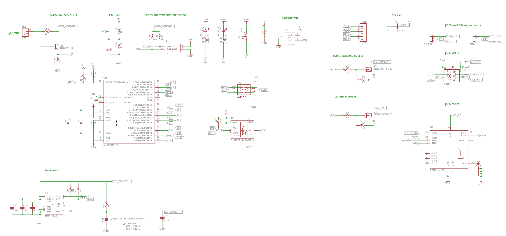
@jesper: I have not much time to check everything but it seems a nice design :wink:
Just one or two things, as I recognize some things :smiley: I have not uploaded my 1.1 design yet, so :
- for pmosfet (radio and sensors) you could go for cheap CJ2305 on ali (which I use) or very good DMP3056L-7 too (Anticimex uses these).
- for pmosfet (radio and sensors). I have removed 100ohms res. I had some trouble, strange. But I let the footprint in case, so now it is 0 ohms.
- if you want something low power, check your batt sensor. Res divider will consume lot of uA. So prefer use higher res, or better put it on VCC_Sensors :wink: (it is something I missed on my booster divider :angry: but changed on my 1.1, so I use high res for my 1.0 boards I have in stock).
-
You could drop the pmos for the radio. Radio consumes around 15-20mA , and the maximum output current for the atmega is 40mA per pin (If I remember right).
Then just connect the VCC of the radio, to a digital io pin on the atmega itself. 3 components saved..
-
I completely agree with @tbowmo :wink:
but in other hand it depends on which radio you plan to use..rfm69w can consumes 45mA max in TX and HW version much more 130mA max in TX.
but for nrf, arduino pin is better strategy I think. big dilemma! -
For small amount prototype I use OSHPark. Just drop Eagle BRD file, cost is 5 USD / square inch (transportcost is included).
https://oshpark.com/For more boards I go to Dirty PCB (but then you need to generate gerberfiles):
http://dirtypcbs.com/To check the exported GERBER files I use the following gerber viewer (in 3D!):
http://mayhewlabs.com/webGerber/ -
@GertSanders: I do the same like you :smiley: and I like mayhew too, very fun. another tool i use sometimes is zofzpcb, not bad too, but mayhew is so great. but just one thing. in your design I don't think you could have the problem, but maybe in future who knows..
Once, one of my design was ok with mayew, oshpark but when I looked at Seeedstudio gerber preview, switching between top/bottom and drills, there was a micro offset. I didn't understand at the moment. it was not distinguable in mayhew, nor in oshpark preview. So who trusts...my design was well 0;0 aligned in eagle...but when I zoomed a lot I saw that my bitmap import added a very micro text silkscreen, out of the board. Seeed was right!
So now when I check gerbers, I check multiple ways to be sure. Seeedstudio gerber preview does not look good, but it is easier sometimes to see this kind of offset.
I hope it can be useful. I just share what I noticed once :wink:
-
@scalz: good tip! I prefer to triple check before committing to a pcbmaker.
Hello! It looks like you're interested in this conversation, but you don't have an account yet.
Getting fed up of having to scroll through the same posts each visit? When you register for an account, you'll always come back to exactly where you were before, and choose to be notified of new replies (either via email, or push notification). You'll also be able to save bookmarks and upvote posts to show your appreciation to other community members.
With your input, this post could be even better 💗
Register Login