Errors in PCB-design?
-
Hi,
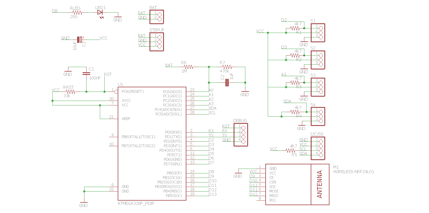
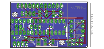
this is my first PCB and my first project with EAGLE. Are there any errors in my schema and my board? Boardsize is 30x50mm...
It's a simple NO-SMD Board which allows to connect a maximum of 5 sensors. Possible sensors are DS18B20, REED-Contacts, PIR or other "normal" analog" or digital sensors (LDR,...)
The resistors in Ports S1-5 are optional (no values). if not needed i just solder a wire or leave it open. S5 is a dual-use port => I2C or other sensor. The sensors can be soldered to the pads or via "jumper-plugs"
Debug is mainly for serial output or uploading a sketch with arduino bootloader.
The stepup-regulator is on the bottom side - a small bob can be soldered here (or left open).
What do you tink about C1 - C3?
C1 is for a good "reset signal" for sketch uploading (auto reset does not work without)
C2 is for stabilizing the monitoring circuit/voltage (R6 & R7)
C3 is for general voltage stabilization...

The nightly meditation must end and i want to order my first PCBs now :D
-
hi Andreas, as far as I can tell there are no errors in the schematic. On the board I see a signal line close to the top left mounting hole. If you use a screw, it could scrape of the cover film and touch the signal. Screws are minimum 1-2 mm wider then the holes they fit in. You could use plastic mounting screws, then no problem.
Make sure there is NO copper under the antenna part. I would add a keep-out area in EAGLE under the NRF24 antenna.
Apart from that: looks cool !
Regarding 3D views of the board, I think you need to check the CAM file used to make the berbers. I used the CAM file from ITEAD, but needed to correct 1 thing: the EXCELLON definition is now "standard" and should be "EXCELLON24" instead of just "EXCELLON". You could also use the CAM for OSHPark, works perfect for me.
-
HI Gert,
thx for your great feedback.
Some ideas: I can draw a line on the pcb where to cut the pcb for the antenna (maybe i draw holes too).
The lines at the holes are not a problem, becaus i already planned to use plastic screws.
I printed the pcb on a piece of paper and placed all components on it. Look cool and everything fits without problems.Some last questions before i place an order:
- What do you think about the sizes of the capacitors? To small, to big?
- Do you know 3mm DUO-LEDs which are low current (2-3mA)?
- Where are you from? ;)
Greetings
Andreas
-
hi Andreas,
if you change your dimension in EAGLE then OSHPark and others will cut the PCB in that form. But you can also just define a "keep out" area with a polygon.
The capacitor seems OK to me. All 100nF I have are 2.54mm pitch. My 10uF capacitor is 5mm diameter (8mm high), the 100uF is 7mm diameter (12mm high).
I am not familiar with 3mm duo-leds.
I live in Wilrijk, south of Antwerpen (Belgium), but I spent some time on other continents and even three months in Munchen as a student working in the research facilities of Siemens in Neu Perlach. I'm assuming you live in Germany.
Gert
