
Errors in PCB-design?
-
Hi,
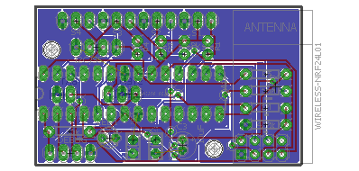
this is my first PCB and my first project with EAGLE. Are there any errors in my schema and my board? Boardsize is 30x50mm...
It's a simple NO-SMD Board which allows to connect a maximum of 5 sensors. Possible sensors are DS18B20, REED-Contacts, PIR or other "normal" analog" or digital sensors (LDR,...)
The resistors in Ports S1-5 are optional (no values). if not needed i just solder a wire or leave it open. S5 is a dual-use port => I2C or other sensor. The sensors can be soldered to the pads or via "jumper-plugs"
Debug is mainly for serial output or uploading a sketch with arduino bootloader.
The stepup-regulator is on the bottom side - a small bob can be soldered here (or left open).
What do you tink about C1 - C3?
C1 is for a good "reset signal" for sketch uploading (auto reset does not work without)
C2 is for stabilizing the monitoring circuit/voltage (R6 & R7)
C3 is for general voltage stabilization...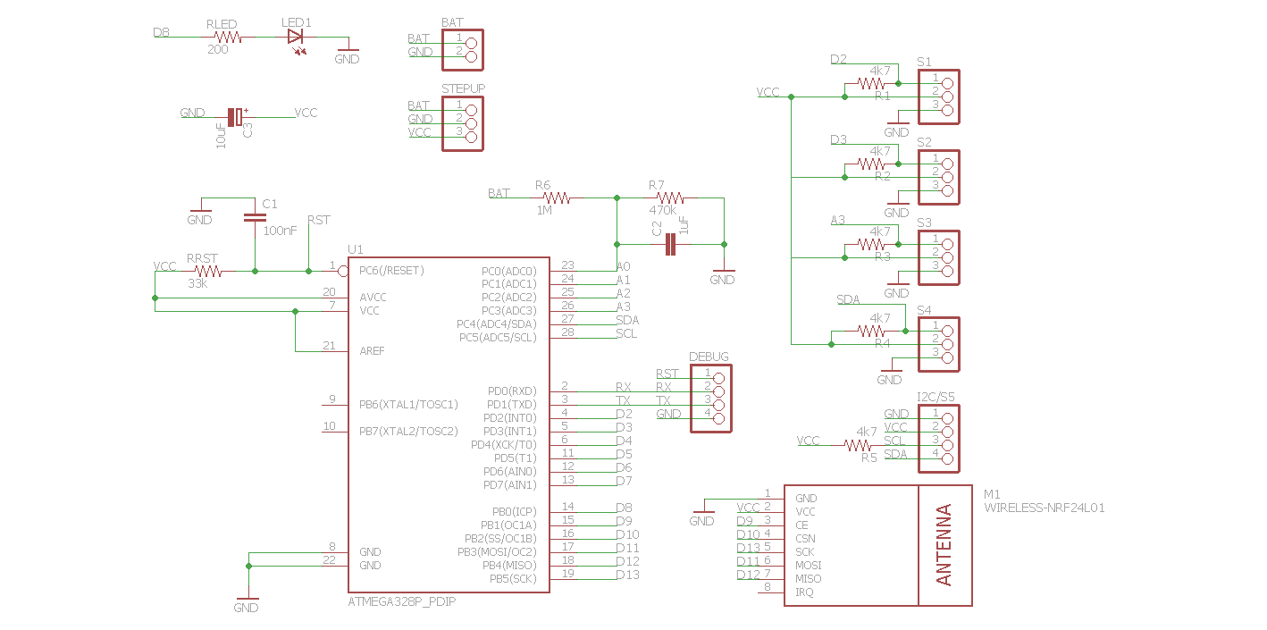
The nightly meditation must end and i want to order my first PCBs now :D
-
hi Andreas, as far as I can tell there are no errors in the schematic. On the board I see a signal line close to the top left mounting hole. If you use a screw, it could scrape of the cover film and touch the signal. Screws are minimum 1-2 mm wider then the holes they fit in. You could use plastic mounting screws, then no problem.
Make sure there is NO copper under the antenna part. I would add a keep-out area in EAGLE under the NRF24 antenna.
Apart from that: looks cool !
Regarding 3D views of the board, I think you need to check the CAM file used to make the berbers. I used the CAM file from ITEAD, but needed to correct 1 thing: the EXCELLON definition is now "standard" and should be "EXCELLON24" instead of just "EXCELLON". You could also use the CAM for OSHPark, works perfect for me.
-
HI Gert,
thx for your great feedback.
Some ideas: I can draw a line on the pcb where to cut the pcb for the antenna (maybe i draw holes too).
The lines at the holes are not a problem, becaus i already planned to use plastic screws.
I printed the pcb on a piece of paper and placed all components on it. Look cool and everything fits without problems.Some last questions before i place an order:
- What do you think about the sizes of the capacitors? To small, to big?
- Do you know 3mm DUO-LEDs which are low current (2-3mA)?
- Where are you from? ;)
Greetings
Andreas
-
hi Andreas,
if you change your dimension in EAGLE then OSHPark and others will cut the PCB in that form. But you can also just define a "keep out" area with a polygon.
The capacitor seems OK to me. All 100nF I have are 2.54mm pitch. My 10uF capacitor is 5mm diameter (8mm high), the 100uF is 7mm diameter (12mm high).
I am not familiar with 3mm duo-leds.
I live in Wilrijk, south of Antwerpen (Belgium), but I spent some time on other continents and even three months in Munchen as a student working in the research facilities of Siemens in Neu Perlach. I'm assuming you live in Germany.
Gert

Hello! It looks like you're interested in this conversation, but you don't have an account yet.
Getting fed up of having to scroll through the same posts each visit? When you register for an account, you'll always come back to exactly where you were before, and choose to be notified of new replies (either via email, or push notification). You'll also be able to save bookmarks and upvote posts to show your appreciation to other community members.
With your input, this post could be even better 💗
Register Login