My own board (50mm x 30mm)
-
Is it possible to order the AC boards from your last picture?
-
I order from OSHpark the v2 of your own board and I have a question, if I run it with 2AA battery for example, I put jumpers (marked red on the picture) and it is working.
But if I want to try with 5v input, like from usb charger, do I need to have a 3.3v regulator for the NRF24+ ? And if yes, do I need other pcb to complete this?
Other question, what is the use of the jumper J1? I'm not sure...
Thanks again !!
-
hi @Carl-H By adding the two jumpers as you do, indeed it wil work with a set of batteries.
J1 connects the VCC circuit with the 3V3 circuit.
3V3 circuit connects to the NRF24. Vcc circuit connects to the power (Vcc and AVcc) of the atmega328.
The jumper you put on the left arrow, is to connect the VRaw input with 3V3 (above).
So by adding the two jumpers you get battery voltage on VCC and on 3V3 circuit, through the JST connector (which is connected to VRaw).
If you want to use 5V, you will need to add a 3V3 regulator. This can be through a companion board like I published on OSHPark (https://oshpark.com/shared_projects/IOHUNYT2), or you could make your own board. You could take the VRaw input and bring to down to 3V3 and connect to the 3V3 circuit. If you put a jumper between Vraw pin and VCC pin instead of between VRaw and 3V3, then VCC will have the 5V.
If you use the companion board, you should not bridge the Vcc and 3V3 circuits or the Vcc and 3V3 circuits.As you guessed, to get 3V3 from a 5V input you need more then just this board.
There are also two pins for a battery holder. One is visible above C9, this is the + side and connected to VBat. The other is right of the LED and R2 and is negative side and connected to GND circuit.
More info on this board I will keep adding here: http://forum.mysensors.org/topic/595/pcb-boards-for-mysensors/30
-
Is it possible to order the AC boards from your last picture?
@Cliff-Karlsson The blue board (AC capable) can be ordered from Dirtypcb's:
http://dirtypcbs.com/view.php?share=12146&accesskey=c3a217d7f31434a5565ecf9bdf3f7dc6
There is no BOM for the moment. I built several variants, and they all work. But I do not consider this my final version of this type of board. The above link points to my first spin of the PCB (first version). There is no v2 right now, but I have some ideas to improve it, and I'm open to suggestions.
I will add the EAGLE files also to the message thread where we collect all the hardware.
Fo the moment most info (images) is only here:
http://forum.mysensors.org/topic/2374/50mm-x-50mm-board-with-different-powering-options/10 -
Just got the board v2 from OSHpark and I would to ask a few questions:
- Can I replace R2 with 220Ohm one?
- I have 16Mhz crystal - hopefully this is not a problem?
I fired the board, but cannot connect it to the Arduino IDE 1.6.5 via the FTDI USB-TTL. I checked the voltage and it is 3V from the battery pack with two jumpers J1 and VBAT to VCC in place. I have used a standard ATMEGA328P_PDIP with an Arduino Uno bootloader I got from the Ebay. Do you think this may be an issue?
Regards
Alex -
@alexsh1 I think running at 16Mhz in 3V is asking too much from the processor. The boot loader for Arduino Uno assumes 16Mhz, and communication with the processor at a much higher speed then I use on my board. That is why I compiled my own boot loader (for 8MHz and serial communications at 36K baud instead of 115K baud).
Also, the boot loader for Arduino Uno assumes there is a LED on pin 13. In my board I moved this to pin 8. This should not block the processor. Having it at 16Mhz while powering it with 3V is more the issue here I think.
If you have an Arduino Uno available, you can burn your own boatloader. The HEX file is added in the topic:
http://forum.mysensors.org/topic/595/pcb-boards-for-mysensors/31
The how to here is:
http://www.gammon.com.au/bootloaderUsing 220 Ohm for R2 should be OK, the led will get a bit more current, but should handle it fine. The port can give 20mA. With 220 Ohm you pull 13mA, so within limits.
-
From another board:
The most common non-5v voltage is of course 3v3 and as you can see at 3v3 the chip is only spec'd at just over 13MHz, people do often run them at 16MHz but that is well out of spec. That's ok if you are playing around, making a widget for yourself etc, but it's not ok for a commercial product, especially if it will be subject to large temperature variations.
Source: http://forum.arduino.cc/index.php?topic=213105.0
At 3V (or thereabouts when using g a set of batteries) you are well under specification. 12MHz would be OK, 16MHz is a bit much.
-
@alexsh1 I think running at 16Mhz in 3V is asking too much from the processor. The boot loader for Arduino Uno assumes 16Mhz, and communication with the processor at a much higher speed then I use on my board. That is why I compiled my own boot loader (for 8MHz and serial communications at 36K baud instead of 115K baud).
Also, the boot loader for Arduino Uno assumes there is a LED on pin 13. In my board I moved this to pin 8. This should not block the processor. Having it at 16Mhz while powering it with 3V is more the issue here I think.
If you have an Arduino Uno available, you can burn your own boatloader. The HEX file is added in the topic:
http://forum.mysensors.org/topic/595/pcb-boards-for-mysensors/31
The how to here is:
http://www.gammon.com.au/bootloaderUsing 220 Ohm for R2 should be OK, the led will get a bit more current, but should handle it fine. The port can give 20mA. With 220 Ohm you pull 13mA, so within limits.
@GertSanders said:
@alexsh1 I think running at 16Mhz in 3V is asking too much from the processor. The boot loader for Arduino Uno assumes 16Mhz, and communication with the processor at a much higher speed then I use on my board. That is why I compiled my own boot loader (for 8MHz and serial communications at 36K baud instead of 115K baud).
Also, the boot loader for Arduino Uno assumes there is a LED on pin 13. In my board I moved this to pin 8. This should not block the processor. Having it at 16Mhz while powering it with 3V is more the issue here I think.
If you have an Arduino Uno available, you can burn your own boatloader. The HEX file is added in the topic:
http://forum.mysensors.org/topic/595/pcb-boards-for-mysensors/31
The how to here is:
http://www.gammon.com.au/bootloaderUsing 220 Ohm for R2 should be OK, the led will get a bit more current, but should handle it fine. The port can give 20mA. With 220 Ohm you pull 13mA, so within limits.
@GertSanders - thanks very much for your comprehensive and quick reply.
OK, this is what I thought. Will have to change crystal to 8Mhz and burn a new bootloader.
Interesting info I found on Nick's web-site regarding my issue:For running at 16 MHz you need at least 3.78V and at 8 MHz you need at least 2.40V. (Caveat: under testing I found that it did not seem to work reliably much under 2.8V at 8 MHz).
[EDIT] That unreliability would have been because of the brown-out reset kicking in at 2.7V. If you are using lower voltages you need to adjust or disable the brown-out detection.
I am planning to run at 8 MHz using the internal oscillator, to save parts and space. Thus you could conceivably run the whole thing off 2 x 1.5V batteries, giving around 3V nominally. However 3 x 1.5V batteries would be OK, and let you run it at 16 MHz.
Taken from here: http://www.gammon.com.au/forum/?id=11637 (Power Supply)
-
@alexsh1 I completely switched off the BoD in my fuse settings, this saves the battery even more. I found that the processor kept working down to around 1,64V. Even my NRF24 worked to that low level, because the last message I received in my Domoticz from that node gave a battery voltage of 1.64V
Anyway, since I monitor all battery levels via a script in Domoticz, there is no need for BoD. -
@gloob To burn a boatloader with Arduino IDE, you will need a second Arduino or working atmega328 onto which you can load a sketch.
I have an older Arduino board (the one I bought when I first started exploring this new hobby), and I use the setup as described in this article: http://www.gammon.com.au/bootloader -
@gloob To burn a boatloader with Arduino IDE, you will need a second Arduino or working atmega328 onto which you can load a sketch.
I have an older Arduino board (the one I bought when I first started exploring this new hobby), and I use the setup as described in this article: http://www.gammon.com.au/bootloader@GertSanders said:
@alexsh1 I completely switched off the BoD in my fuse settings, this saves the battery even more. I found that the processor kept working down to around 1,64V. Even my NRF24 worked to that low level, because the last message I received in my Domoticz from that node gave a battery voltage of 1.64V
Anyway, since I monitor all battery levels via a script in Domoticz, there is no need for BoD.Yes, I noticed that you have atmega328pO4M8i.bootloader.extended_fuses=0x07 which is as you said switches off all BoD levels.
Thanks for an interesting info regarding the voltage. This is a very good news. I guess you are getting a notification in Domoticz if a battery level goes down to 1.64V?
I'am going to setup a programmer on mega 2560 tonight, but meantime ordered one of the programming shields to streamline the process - http://www.boardstuff.co.uk/
-
@alexsh1 I actually set up a notification on each Voltage sensor within Domoticz, so that I get a prowl message when the voltage drops below 2V. This then gives me some time to replace the batteries. The 1.64V was when I intentionally let a sensornode die out, just to see what would happen. I never let the voltage drop that low now. All my nodes now have batteries that should last at least 9-12 months (depends on the sensor and it's activities).
-
@GertSanders
Thanks for your help. I was now able to burn the bootloader and will start testing the board tomorrow when I have a valid 3,3V source to power the radio.
Can I power the radio from an FTDI programmer if the programmer is set to 3,3V power? If yes, how to set the two jumpers? -
@gloob if you power via a 3V3 FTDI interface, then you only need to close jumper 1 to connect the Vcc corcuit with the 3V3 circuit.
-
@GertSanders
Thanks for your support. I have now the serial gateway sketch running and output of the arduino seems good:0;0;3;0;9;gateway started, id=0, parent=0, distance=0 0;0;3;0;14;Gateway startup complete.I will now order some Si7021 sensors and continue my testing.
Can I use the following sensors:
Si7021 Industrial High Precision Humidity Sensor I2C Interface for Arduino
-
@gloob I'm using the same sensors for Temperature and Humidity. The pinout of these boards is what I based my pinout on my red board on. (3V3, GND, SCL, SDA). I'm using now 5 of these.
-
Ok, after a few long days I managed to burn the bootloader. For those who are struggling with the same problem please note the following:
- Use Nick Gammon's website and optiboot bootloader (512kb only). I had a standard ATmegaBOOT_168_atmega328_pro_8MHz_hex (Lilypad 8 MHz loader) and could not make it work with 3.3.v.
- Important: the 2048kb bootloader's (Lilypad 8MHz) address is 0x7800. For the optiboot (512Kb) you need to change it for 0x7E00. Now everything works fine - I just need now to change fuses to make sure the voltage can go down below 2V.
@GertSanders I wonder what sketches do you use with this board? it is nice to have Si7021 (it is pin-for-pin for your board) for temp and humidity.
-
@alexsh1 I make my own sketches, the one for my board with SI7021 is used most in my house. I also have a repeater, a GSM node, a sleeper node which wakes up when switches are tripped (basis for upcoming door sensor node). I work with the development version of the library (1.6.0-beta) of Mysensors
I added my Temp/Hum sketch as inspiration: TEMPNODESI7021.ino
-
Interesting
@GertSanders GSM node? is it a standalone or you have it hooked up to this node?
I have a GSM node connected to a couple of SSRs to control water heating - sadly this is not connected to MySensors -
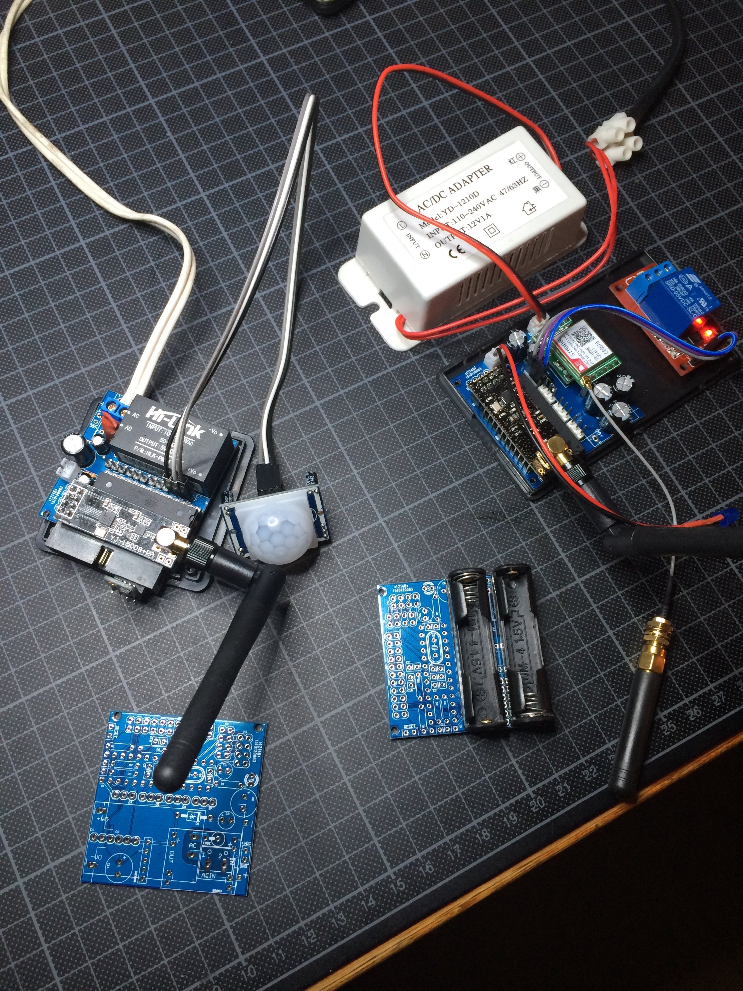
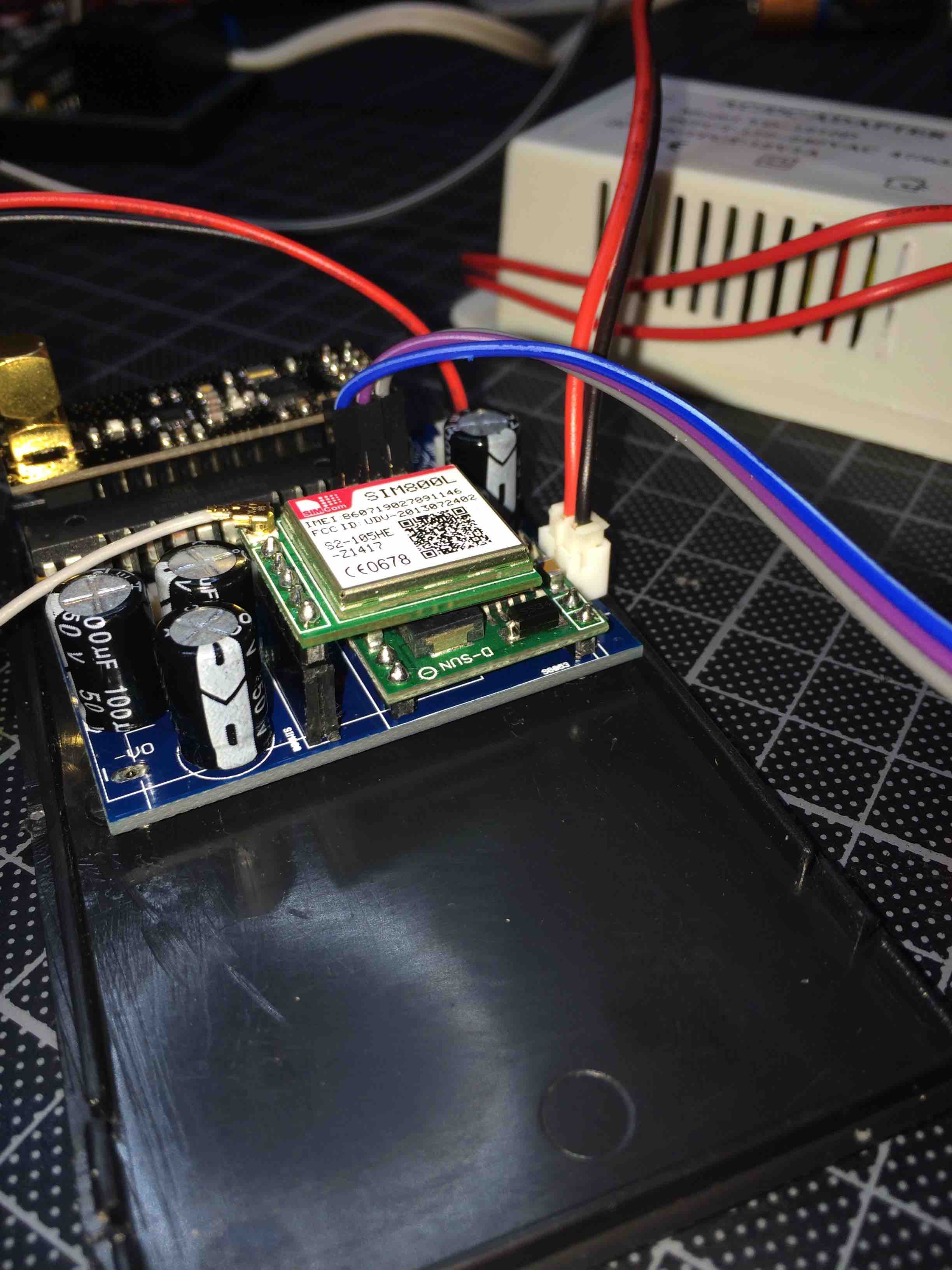
@alexsh1 It is based on my AC capable board, is a normal atmega328p board, but with a SIM800L mounted on it. This module allows me to send and receive SMS's, and I use one of the digital output pins to control a waterpump. I have a second AC based board ready which will be my MySensors SMS gateway. This means it will be able to receive V_TEXT and send that to the default GSM number as a SMS. It should be possible to receive SMS and send that as V_TEXT to other nodes, but so far I have not started the design of the second sketch yet.
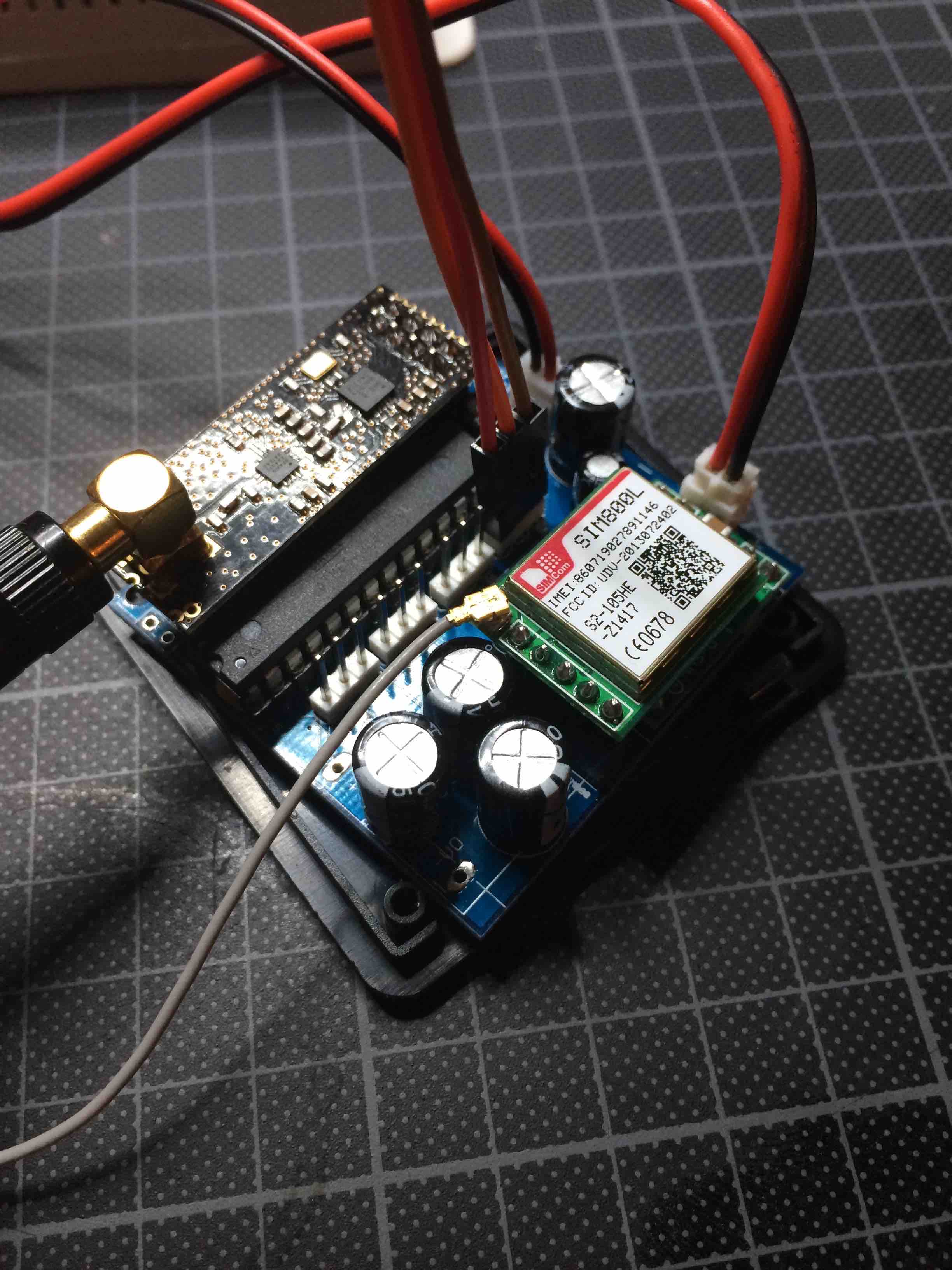
You see it here also (top right) with the relay module and the white AC-DC converter connected.
Side view:
Hello! It looks like you're interested in this conversation, but you don't have an account yet.
Getting fed up of having to scroll through the same posts each visit? When you register for an account, you'll always come back to exactly where you were before, and choose to be notified of new replies (either via email, or push notification). You'll also be able to save bookmarks and upvote posts to show your appreciation to other community members.
With your input, this post could be even better 💗
Register Login