Skip to content
  • MySensors
  • OpenHardware.io
  • Categories
  • Recent
  • Tags
  • Popular
Skins
  • Light
  • Brite
  • Cerulean
  • Cosmo
  • Flatly
  • Journal
  • Litera
  • Lumen
  • Lux
  • Materia
  • Minty
  • Morph
  • Pulse
  • Sandstone
  • Simplex
  • Sketchy
  • Spacelab
  • United
  • Yeti
  • Zephyr
  • Dark
  • Cyborg
  • Darkly
  • Quartz
  • Slate
  • Solar
  • Superhero
  • Vapor

  • Default (No Skin)
  • No Skin
Collapse
Brand Logo
  1. Home
  2. Hardware
  3. Fried sensor board with external AC/DC adapter

Fried sensor board with external AC/DC adapter

Scheduled Pinned Locked Moved Hardware
11 Posts 4 Posters 3.4k Views 3 Watching
  • Oldest to Newest
  • Newest to Oldest
  • Most Votes
Reply
  • Reply as topic
Log in to reply
This topic has been deleted. Only users with topic management privileges can see it.
  • M Offline
    M Offline
    mardah
    Hardware Contributor
    wrote on last edited by
    #2

    0_1453971227089_sensorboard.png

    1 Reply Last reply
    0
    • sundberg84S Offline
      sundberg84S Offline
      sundberg84
      Hardware Contributor
      wrote on last edited by sundberg84
      #3

      A read somewhere here that cheap clones use cheap/fake voltage converter and supplying 12v to RAW is living on the edge even if 12v is within limits.

      Maybe you have a bad batch of voltage regulators?
      Did you try with another AC/DC converter? It can limit your search.

      Controller: Proxmox VM - Home Assistant
      MySensors GW: Arduino Uno - W5100 Ethernet, Gw Shield Nrf24l01+ 2,4Ghz
      MySensors GW: Arduino Uno - Gw Shield RFM69, 433mhz
      RFLink GW - Arduino Mega + RFLink Shield, 433mhz

      1 Reply Last reply
      0
      • M Offline
        M Offline
        mardah
        Hardware Contributor
        wrote on last edited by
        #4

        The MCP1703 does provide 3.3V until it fries. But yes, it could be a non genuine voltage regulator.

        1 Reply Last reply
        0
        • sundberg84S Offline
          sundberg84S Offline
          sundberg84
          Hardware Contributor
          wrote on last edited by
          #5

          How about the HLK-PM01 or use a AC to 5v DC converter (Iphone plug)?
          Then you dont need regulate your voltage twise.

          Controller: Proxmox VM - Home Assistant
          MySensors GW: Arduino Uno - W5100 Ethernet, Gw Shield Nrf24l01+ 2,4Ghz
          MySensors GW: Arduino Uno - Gw Shield RFM69, 433mhz
          RFLink GW - Arduino Mega + RFLink Shield, 433mhz

          1 Reply Last reply
          0
          • M mardah

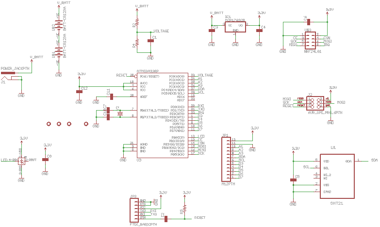
            I have fried several sensor boards when using an external AC/DC adapter supplying 12V/1A. The voltage is regulated with a MCP1703 with 1u caps on both input and output.

            I think the problem appears when I unplug and plug in the DC jack to quick? Not sure though. Sometimes just the voltage regulator fries and sometimes the ATMega
            fries as well.

            If it doesn't fry the first time I plug in the DC jack it can run for a long time.

            What could be the problem? Build up of voltage in the AC/DC adapter, the caps? Voltage spikes?

            When running on two CR123 in series I have not seen any problems with the sensor board.

            YveauxY Offline
            YveauxY Offline
            Yveaux
            Mod
            wrote on last edited by
            #6

            @mardah what's the maximum input voltage for the MCP1703?
            I've fried some AM1117's supplying '12V' from an unregulated adapter.

            http://yveaux.blogspot.nl

            1 Reply Last reply
            0
            • M Offline
              M Offline
              mardah
              Hardware Contributor
              wrote on last edited by
              #7

              The MCP1703 should handle up to 20V input. Maybe the input cap is 10V , I guess it would handle 12V most of the time?

              YveauxY 1 Reply Last reply
              0
              • M mardah

                The MCP1703 should handle up to 20V input. Maybe the input cap is 10V , I guess it would handle 12V most of the time?

                YveauxY Offline
                YveauxY Offline
                Yveaux
                Mod
                wrote on last edited by
                #8

                @mardah said:

                he MCP1703 should handle up to 20V input.

                Datasheet states 18V as absolute maximum (http://ww1.microchip.com/downloads/en/DeviceDoc/22049e.pdf).
                Also check the maximum on the cap, as you already suggested.

                http://yveaux.blogspot.nl

                1 Reply Last reply
                0
                • m26872M Offline
                  m26872M Offline
                  m26872
                  Hardware Contributor
                  wrote on last edited by
                  #9

                  I've fried a lot of Arduino boards by powering on my breadboard AC/DC supply while still having the FTDI port supply from Laptop connected or vs. (Laptop is on its own AC/DC.)
                  Change Atmega has always saved the boards then, but I don't use the v-reg very often.

                  YveauxY 1 Reply Last reply
                  0
                  • m26872M m26872

                    I've fried a lot of Arduino boards by powering on my breadboard AC/DC supply while still having the FTDI port supply from Laptop connected or vs. (Laptop is on its own AC/DC.)
                    Change Atmega has always saved the boards then, but I don't use the v-reg very often.

                    YveauxY Offline
                    YveauxY Offline
                    Yveaux
                    Mod
                    wrote on last edited by
                    #10

                    @m26872 ground-loops... Terrible :rage:

                    http://yveaux.blogspot.nl

                    1 Reply Last reply
                    0
                    • M Offline
                      M Offline
                      mardah
                      Hardware Contributor
                      wrote on last edited by
                      #11

                      I soldered just the two caps and an MCP1703 on a new board and have not manage to fry it. So maybe there is another cause. I'm suspecting the WS2812, it's new on my latest batch of sensor boards. But I don't understand how it could destroy the voltage regulator or ATMega.

                      Maybe something is wrong with the PCB layout causing some unwanted currents?

                      1 Reply Last reply
                      0
                      Reply
                      • Reply as topic
                      Log in to reply
                      • Oldest to Newest
                      • Newest to Oldest
                      • Most Votes


                      19

                      Online

                      11.7k

                      Users

                      11.2k

                      Topics

                      113.1k

                      Posts


                      Copyright 2025 TBD   |   Forum Guidelines   |   Privacy Policy   |   Terms of Service
                      • Login

                      • Don't have an account? Register

                      • Login or register to search.
                      • First post
                        Last post
                      0
                      • MySensors
                      • OpenHardware.io
                      • Categories
                      • Recent
                      • Tags
                      • Popular