Relay turns on when input is LOW?!
-
The title says it all: I have connected a relay to my network and it switches power on (led on the relay lights up), when the input pin goes low and vice versa.
Thats a little bit confusing, when switching off something in the controller UI and the device is switching on ;) and i don't think, that zwitching the state in the arduino code is the way to go :D
any idea whats wrong here? Wiring is straight forward (vcc & gnd with corresponding pins on relay + D2 to I1 on the relay).
The code is the the one from the examples (as far as I remember :D ).
I inserted some debug statements to prevent stupid errors on my side ;)
    Serial.print("arduino pin: ");
    Serial.println(message.sensor + FIRST_DIGITAL_RELAY_OUTPUT);
    Serial.print("message.bool: ");
    Serial.println(message.getBool());
    digitalWrite(message.sensor + FIRST_DIGITAL_RELAY_OUTPUT, message.getBool() ? RELAY_ON : RELAY_OFF);
=>
arduino pin: 2
message.bool: 1
results in switched off relay.
Thanks for helping
EDIT: maybe "hardware" is the wrong section and "Troubleshooting" a better location ;) If thats the case: please move the thread if possible
-
Not sure what kind of relay setup you are using, but are you using a pull-up or pull-down resistor on your data line? If you are using pull-up resistors, the data line is always high and needs to be pulled low to be active. Check that you are not using the internal pull-up resistors on your data line. For this you should use a pull-down resistor if your relay setup does not already have one.
-
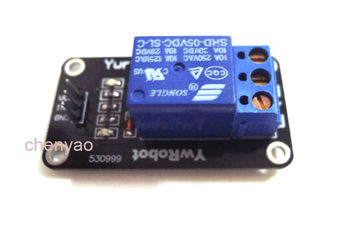
If you are using a relay module similar to this one

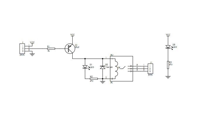
They often use a PNP transistor to drive the relay. That means you will need to switch the arduino output low to turn on the relay, as you have discovered.
As @mfalkvidd has said the simple fix may be to reverse the #defines
Here is what the relay circuit would look like. They would also likely have a resistor from the transistor base to vcc to ensure the transistor turns off

-
Ah that explains it for me. Thanks for the dettailed answer. I will @mfalkvidd's and switch the defines. thank you all ;)
Greetings
