[Solved] Communication from Gateway to Sensor node not working
-
Hello guys,
I have built temperature sensor DS18B20 using the example sketch, I also have a simple on off switch and LED on my sensor node. I am using Arduino Uno for both Gateway and sensor node.
My sensors work and show values on the MYSController. Now when I try to control LED using the MYSController, it doesn't work.
Here is the screenshot of what happens in MYSController:
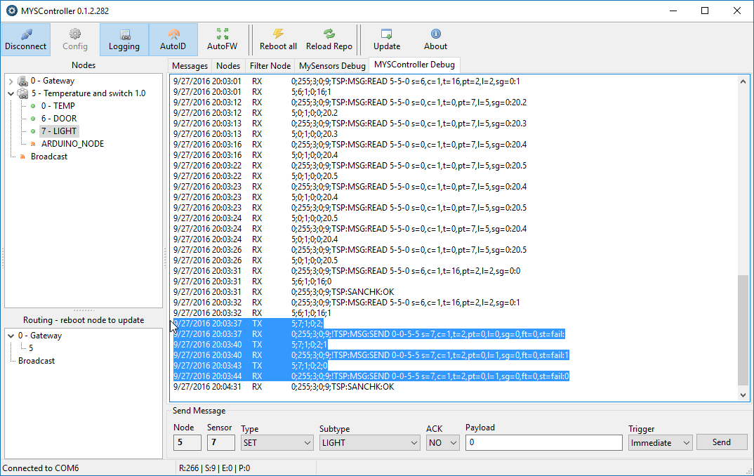
I have tried with with and without payload. My code doesn't really need a payload to turn on or off the LED. It just toggles the state of an LED when it receives V_LIGHT message.
Here is my code for sensor node:
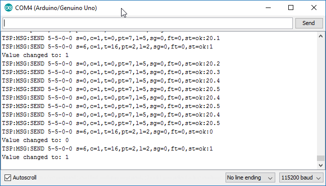
// Enable debug prints to serial monitor
#define MY_DEBUG

// Enable and select radio type attached
#define MY_RADIO_NRF24
//#define MY_RADIO_RFM69

#include <SPI.h>
#include <MySensors.h>
#include <DallasTemperature.h>
#include <OneWire.h>

#define COMPARE_TEMP 1 // Send temperature only if changed? 1 = Yes 0 = No

#define ONE_WIRE_BUS 3 // Pin where dallase sensor is connected
#define MAX_ATTACHED_DS18B20 16
unsigned long SLEEP_TIME = 30000; // Sleep time between reads (in milliseconds)
OneWire oneWire(ONE_WIRE_BUS); // Setup a oneWire instance to communicate with any OneWire devices (not just Maxim/Dallas temperature ICs)
DallasTemperature sensors(&oneWire); // Pass the oneWire reference to Dallas Temperature.
float lastTemperature[MAX_ATTACHED_DS18B20];
int numSensors=0;
bool receivedConfig = false;
bool metric = true;


// Initialize temperature message
MyMessage msg(0,V_TEMP);

//Initialize switch message
MyMessage msg1(6, V_TRIPPED);


void before()
{
  // Startup up the OneWire library
  sensors.begin();
}

void setup()
{
  // requestTemperatures() will not block current thread
  sensors.setWaitForConversion(false);

  // Setup the buttons for switch
  pinMode(2, INPUT);

  // Activate internal pull-ups
  digitalWrite(2, HIGH);

  //Set LED pin to OUTPUT
  pinMode (4, OUTPUT);

}

void presentation() {
  // Send the sketch version information to the gateway and Controller
  sendSketchInfo("Temperature and switch", "1.0");

  // Fetch the number of attached temperature sensors
  numSensors = sensors.getDeviceCount();

  // Present all sensors to controller
  //for (int i=0; i<numSensors && i<MAX_ATTACHED_DS18B20; i++) {
     present(0, S_TEMP);

     //preset the switch
     present(6, S_DOOR);

     //present LED
     present(7, S_LIGHT);

  }

void loop()
{
  // Fetch temperatures from Dallas sensors
  sensors.requestTemperatures();

  // query conversion time and sleep until conversion completed
  int16_t conversionTime = sensors.millisToWaitForConversion(sensors.getResolution());
  // sleep() call can be replaced by wait() call if node need to process incoming messages (or if node is repeater)
  sleep(conversionTime);

  // Read temperatures and send them to controller
  for (int i=0; i<numSensors && i<MAX_ATTACHED_DS18B20; i++) {

    // Fetch and round temperature to one decimal
    float temperature = static_cast<float>(static_cast<int>((getConfig().isMetric?sensors.getTempCByIndex(i):sensors.getTempFByIndex(i)) * 10.)) / 10.;

    // Only send data if temperature has changed and no error
    #if COMPARE_TEMP == 1
    if (lastTemperature[i] != temperature && temperature != -127.00 && temperature != 85.00) {
    #else
    if (temperature != -127.00 && temperature != 85.00) {
    #endif

      // Send in the new temperature
      send(msg.setSensor(i).set(temperature,1));
      // Save new temperatures for next compare
      lastTemperature[i]=temperature;
    }
  }
  //sleep(SLEEP_TIME);

  //Code for switch

  uint8_t value;
  static uint8_t sentValue=2;

  value = digitalRead(2);

  if (value != sentValue) {
     // Value has changed from last transmission, send the updated value
     send(msg1.set(value==HIGH ? 1 : 0));
     digitalWrite(8,!(digitalRead(8)));

     String string = "Value changed to: ";

     Serial.println(string += value);
     sentValue = value;
  }
 // Sleep until something happens with the sensor
  //sleep(0,CHANGE,0);
}

void receive(const MyMessage &message)
{

  Serial.println("Received command");
  //Check for the message from controller
  if (message.type==V_LIGHT)
  {
    digitalWrite(4, !digitalRead(4));
    Serial.println("LED status changed");
  }
}
For gateway I am using the example code without making any change. When I send command using MYSController, I can see RX LED blink on the Gateway Arduino but nothing on the sensor node serial monitor.
Serial Monitor for sensor node:
What am I doing wrong?
I will really appreciate the help.Thank You,
Vaibhav -
Looks like the radio communication is fine!?
What kind of hardware do you use to control LED?Controller: Proxmox VM - Home Assistant
MySensors GW: Arduino Uno - W5100 Ethernet, Gw Shield Nrf24l01+ 2,4Ghz
MySensors GW: Arduino Uno - Gw Shield RFM69, 433mhz
RFLink GW - Arduino Mega + RFLink Shield, 433mhz -
Looks like the radio communication is fine!?
What kind of hardware do you use to control LED?@sundberg84
I just have LED connected to the pin 4 of Arduino.
I have written code such that when receive() is executed the LED is toggled. -
@sundberg84
I just have LED connected to the pin 4 of Arduino.
I have written code such that when receive() is executed the LED is toggled.@palande.vaibhav - and when you recieve the command it doesnt turn on?
What does this mean?digitalWrite(4, !digitalRead(4));In the relaysketch its this;
digitalWrite(message.sensor-1+RELAY_1, message.getBool()?RELAY_ON:RELAY_OFF);Try HIGH/LOW on a normal led/blink sketch and see if that works.
Controller: Proxmox VM - Home Assistant
MySensors GW: Arduino Uno - W5100 Ethernet, Gw Shield Nrf24l01+ 2,4Ghz
MySensors GW: Arduino Uno - Gw Shield RFM69, 433mhz
RFLink GW - Arduino Mega + RFLink Shield, 433mhz -
@palande.vaibhav - and when you recieve the command it doesnt turn on?
What does this mean?digitalWrite(4, !digitalRead(4));In the relaysketch its this;
digitalWrite(message.sensor-1+RELAY_1, message.getBool()?RELAY_ON:RELAY_OFF);Try HIGH/LOW on a normal led/blink sketch and see if that works.
@sundberg84
No it doesn't turn on. And I even don't see anything on the serial monitor for the sensor node. I think I should be able to see the READ on the serial monitor for the sensor node. But I don't get that on there.digitalWrite(4, !digitalRead(4));This means,
digitalRead(4)------> Read the value at pin 4.
!-----> Toggle it, that is after reading the value, if it is 0 then make it one and if it is 1 make it 0.
digitalWrite(4,----> Write it back to pin 4.digitalWrite(message.sensor-1+RELAY_1, message.getBool()?RELAY_ON:RELAY_OFF);This line actually checks for the payload that comes with the received signal and makes RELAY_ON or RELAY_OFF decision accordingly.
So, I am doing much simpler task than relay example. I am trying to not even check what the received message says, I am just checking if I get the message or not and make LED toggle if I do get the message. -
@sundberg84
No it doesn't turn on. And I even don't see anything on the serial monitor for the sensor node. I think I should be able to see the READ on the serial monitor for the sensor node. But I don't get that on there.digitalWrite(4, !digitalRead(4));This means,
digitalRead(4)------> Read the value at pin 4.
!-----> Toggle it, that is after reading the value, if it is 0 then make it one and if it is 1 make it 0.
digitalWrite(4,----> Write it back to pin 4.digitalWrite(message.sensor-1+RELAY_1, message.getBool()?RELAY_ON:RELAY_OFF);This line actually checks for the payload that comes with the received signal and makes RELAY_ON or RELAY_OFF decision accordingly.
So, I am doing much simpler task than relay example. I am trying to not even check what the received message says, I am just checking if I get the message or not and make LED toggle if I do get the message.@palande.vaibhav
i think the answer is in the code// sleep() call can be replaced by wait() call if node need to process incoming messages (or if node is repeater) sleep(conversionTime);Replace sleep(); by wait();
During a sleep the GW does not receives the message acknowledge and thus claims the broadcast did fail.
-
@palande.vaibhav
i think the answer is in the code// sleep() call can be replaced by wait() call if node need to process incoming messages (or if node is repeater) sleep(conversionTime);Replace sleep(); by wait();
During a sleep the GW does not receives the message acknowledge and thus claims the broadcast did fail.
@BartE said:
@palande.vaibhav
i think the answer is in the code// sleep() call can be replaced by wait() call if node need to process incoming messages (or if node is repeater) sleep(conversionTime);Replace sleep(); by wait();
During a sleep the GW does not receives the message acknowledge and thus claims the broadcast did fail.
This worked.
Thanks a lot for the help. I guess I need to read stuff properly.Thanks for the help.
Hello! It looks like you're interested in this conversation, but you don't have an account yet.
Getting fed up of having to scroll through the same posts each visit? When you register for an account, you'll always come back to exactly where you were before, and choose to be notified of new replies (either via email, or push notification). You'll also be able to save bookmarks and upvote posts to show your appreciation to other community members.
With your input, this post could be even better 💗
Register Login