[Solved] NRF24L01+ Serial Gateway not starting ( Sanity check failed )
-
Hello Guys,
i tried to build my first mySensors - Serial Gateway.
It does not seem to work, since the serial monitor gives the following output messages:0;255;3;0;9;Starting gateway (RNNGA-, 2.0.0) 0;255;3;0;9;TSM:INIT 0;255;3;0;9;RF24:write register, reg=0, value=14 0;255;3;0;9;RF24:write register, reg=3, value=3 0;255;3;0;9;RF24:write register, reg=4, value=95 0;255;3;0;9;RF24:write register, reg=5, value=76 0;255;3;0;9;RF24:write register, reg=6, value=35 0;255;3;0;9;RF24:read register, reg=6, value=255 0;255;3;0;9;RF24:read register, reg=5, value=255 0;255;3;0;9;RF24:Sanity check failed: configuration mismatch! Check wiring, replace module or non-P version 0;255;3;0;9;!TSM:RADIO:FAIL 0;255;3;0;9;!TSM:FAILURE 0;255;3;0;9;TSM:PDT 0;255;3;0;9;RF24:write register, reg=0, value=12 0;255;3;0;9;RF24:power downI setup my software like this:
- Download and install Arduino IDE.
- In Arduino IDE, downloaded the MySensors library
- I took the sketch from the example GatewaySerial ( File/Examples/MySensors/GatewaySerial )
- Uploaded the sketch with these 2 additional Defines:
#define MY_NODE_ID 124
#define MY_DEBUG_VERBOSE_RF24
Since i thought the problem could be, that i need a controller to get rid of those error messages, i put the my_node_id to a random value, and to get some more error details i put the verbose_rf24 in the defines.
So the final sketch, that i'm uploading is:
  /**
 * The MySensors Arduino library handles the wireless radio link and protocol
 * between your home built sensors/actuators and HA controller of choice.
 * The sensors forms a self healing radio network with optional repeaters. Each
 * repeater and gateway builds a routing tables in EEPROM which keeps track of the
 * network topology allowing messages to be routed to nodes.
 *
 * Created by Henrik Ekblad <henrik.ekblad@mysensors.org>
 * Copyright (C) 2013-2015 Sensnology AB
 * Full contributor list: https://github.com/mysensors/Arduino/graphs/contributors
 *
 * Documentation: http://www.mysensors.org
 * Support Forum: http://forum.mysensors.org
 *
 * This program is free software; you can redistribute it and/or
 * modify it under the terms of the GNU General Public License
 * version 2 as published by the Free Software Foundation.
 *
 *******************************
 *
 * DESCRIPTION
 * The ArduinoGateway prints data received from sensors on the serial link.
 * The gateway accepts input on seral which will be sent out on radio network.
 *
 * The GW code is designed for Arduino Nano 328p / 16MHz
 *
 * Wire connections (OPTIONAL):
 * - Inclusion button should be connected between digital pin 3 and GND
 * - RX/TX/ERR leds need to be connected between +5V (anode) and digital pin 6/5/4 with resistor 270-330R in a series
 *
 * LEDs (OPTIONAL):
 * - To use the feature, uncomment MY_LEDS_BLINKING_FEATURE in MyConfig.h
 * - RX (green) - blink fast on radio message recieved. In inclusion mode will blink fast only on presentation recieved
 * - TX (yellow) - blink fast on radio message transmitted. In inclusion mode will blink slowly
 * - ERR (red) - fast blink on error during transmission error or recieve crc error
 *
 */

// Enable debug prints to serial monitor
#define MY_DEBUG


// Enable and select radio type attached
#define MY_RADIO_NRF24
//#define MY_RADIO_RFM69

// Set LOW transmit power level as default, if you have an amplified NRF-module and
// power your radio separately with a good regulator you can turn up PA level.
#define MY_RF24_PA_LEVEL RF24_PA_LOW

// Enable serial gateway
#define MY_GATEWAY_SERIAL

// Define a lower baud rate for Arduino's running on 8 MHz (Arduino Pro Mini 3.3V & SenseBender)
#if F_CPU == 8000000L
#define MY_BAUD_RATE 38400
#endif

// Flash leds on rx/tx/err
#define MY_LEDS_BLINKING_FEATURE
// Set blinking period
#define MY_DEFAULT_LED_BLINK_PERIOD 300

// Inverses the behavior of leds
//#define MY_WITH_LEDS_BLINKING_INVERSE

// Enable inclusion mode
#define MY_INCLUSION_MODE_FEATURE
// Enable Inclusion mode button on gateway
#define MY_INCLUSION_BUTTON_FEATURE

// Inverses behavior of inclusion button (if using external pullup)
//#define MY_INCLUSION_BUTTON_EXTERNAL_PULLUP

// Set inclusion mode duration (in seconds)
#define MY_INCLUSION_MODE_DURATION 60
// Digital pin used for inclusion mode button
#define MY_INCLUSION_MODE_BUTTON_PIN  3

// Uncomment to override default HW configurations
//#define MY_DEFAULT_ERR_LED_PIN 4  // Error led pin
//#define MY_DEFAULT_RX_LED_PIN  6  // Receive led pin
//#define MY_DEFAULT_TX_LED_PIN  5  // the PCB, on board LED

#define MY_NODE_ID 124
#define MY_DEBUG_VERBOSE_RF24

#include <SPI.h>
#include <MySensors.h>

void setup() {
  // Setup locally attached sensors
}

void presentation() {
 // Present locally attached sensors
}

void loop() {
    // Send locally attached sensor data here
}
The OS I'm using running arduino IDE:
Windows 10 ( I also tried it with my macbook pro MacOs X, same result. )The Hardware, that I'm using:
- Arduino Nano with CH340g Chip ( Working without manually installing driver on win10 )
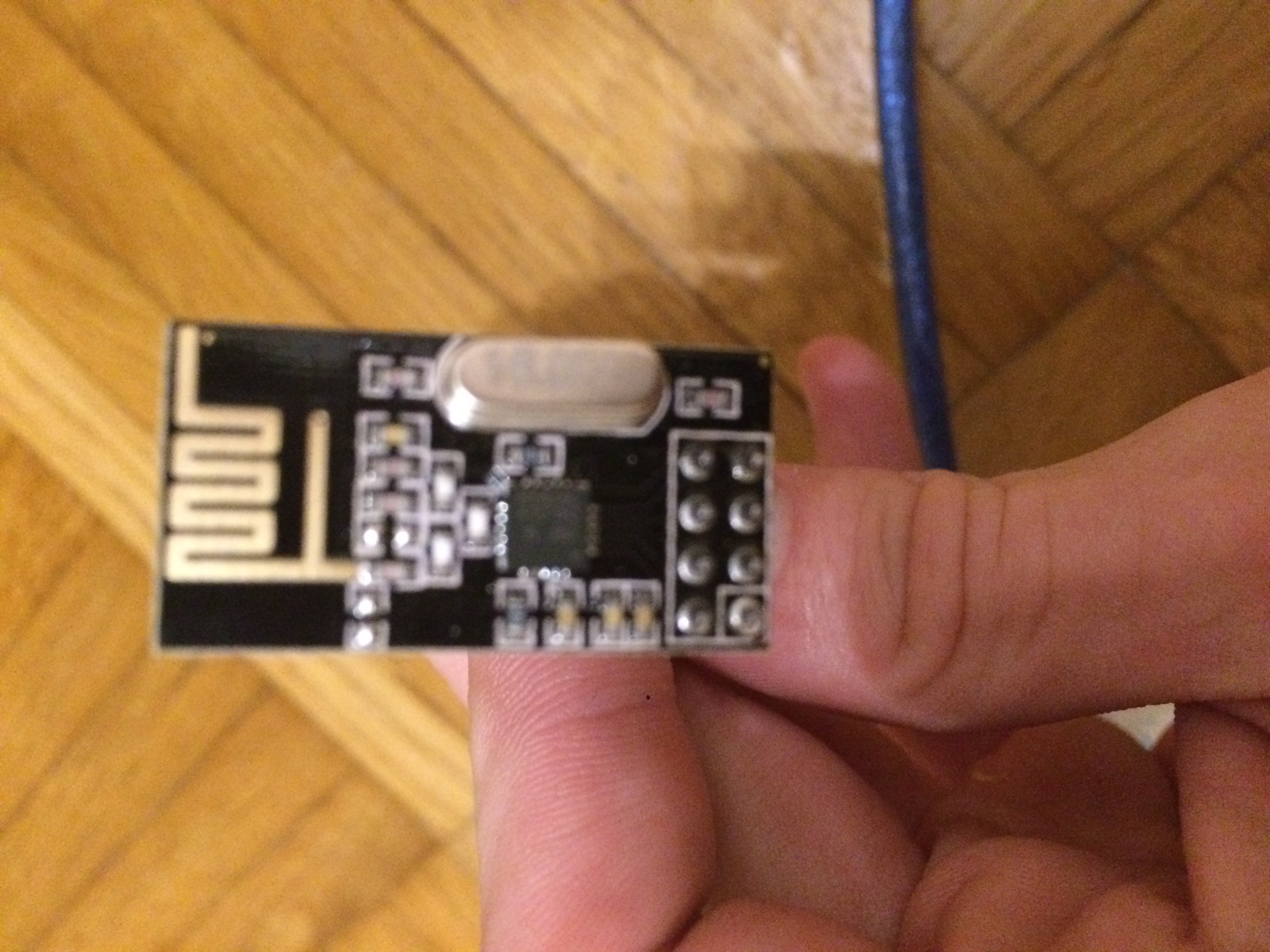
- NRF24L01+, The text on the chip is:
NRF M
24L01+
1452AB
- Capacitor 4.7uF
- Jumper Cables
- Usb - to MicroUsb Cable
- Board
What i tried so far:
- Replacing the NRF24L01+ with ones from a different manufacturer.
- Downloading MySensors API manually from Homepage and copy paste the sample from the MySensors Site.
- Re-wiring all the components.
- Searching forum and google for similar problems.
Sadly, nothing of this helped me so far.
Here's how i wired things up:
Note: For simplicity i used the same colors for my cables as the ones in the exampleArduino:
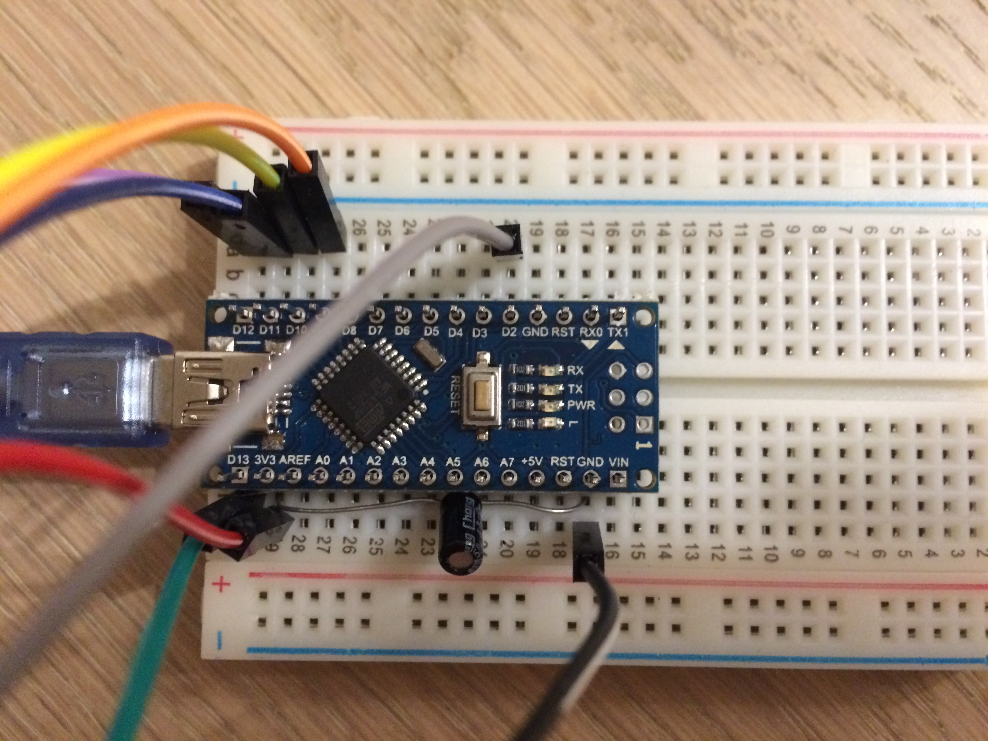
NRF24L01+:
If you have any ideas what i could have missed, or what i could try to get it working, please let me know.
Thank you in advance. -
Hello.
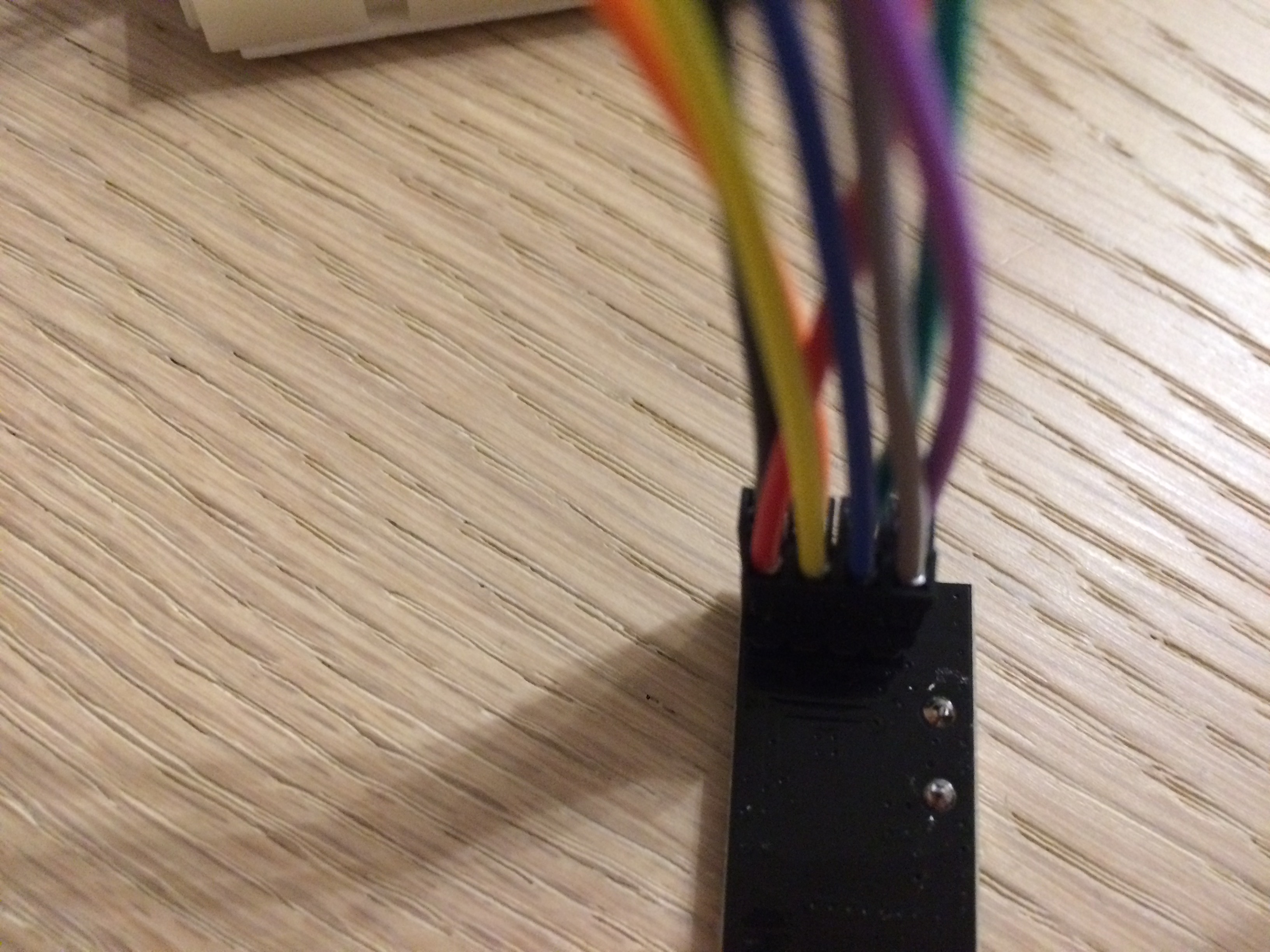
have you missed to solder pinheaders to your arduino nano ? on the pics it looks like..
That would explain your miswiring error in log.I hope this helps.
Hello! It looks like you're interested in this conversation, but you don't have an account yet.
Getting fed up of having to scroll through the same posts each visit? When you register for an account, you'll always come back to exactly where you were before, and choose to be notified of new replies (either via email, or push notification). You'll also be able to save bookmarks and upvote posts to show your appreciation to other community members.
With your input, this post could be even better 💗
Register Login