Max6675 Thermocouple project
-
Hi, just started to explore the MySensors possibilities. The first project I'm building is a High temperature MAX6675 Thermocouple which send data to the MQTT broker.
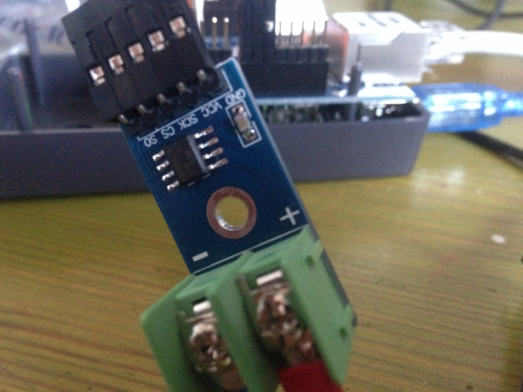
So I ordered some parts and started building the gateway with an arduino uno and Ethernet shield. Than connected the Max6675 and gave it a go!
Although the set-up seems to be quit simple I can not get any temperature read from the sensor?
If I connect it like some of the samples I found I end up with this:0;255;3;0;9;MCO:BGN:INIT GW,CP=R-NGA--,VER=2.1.1 IP: 192.168.0.87 0;255;3;0;9;MCO:BGN:STP MAX6675 test 0;255;3;0;9;MCO:REG:NOT NEEDED 0;255;3;0;9;MCO:BGN:INIT OK,TSP=NA IP: 192.168.0.87 0;255;3;0;9;Attempting MQTT connection... 0;255;3;0;9;MQTT connected 0;255;3;0;9;Sending message on topic: mygateway1-out/0/255/0/0/17 0;255;3;0;9;Sending message on topic: mygateway1-out/0/255/3/0/11 0;255;3;0;9;Sending message on topic: mygateway1-out/0/255/3/0/12 0;255;3;0;9;Sending message on topic: mygateway1-out/0/10/0/0/6 Deg C = nan Deg F = nan Deg C = nan Deg F = nan Deg C = nan Deg F = nan Deg C = nan Deg F = nan Deg C = nan Deg F = nan Deg C = nan Deg F = nan Deg C = nan Deg F = nan Deg C = nan Deg F = nan Deg C = nan Deg F = nan Deg C = nan Deg F = nan Deg C = nan Deg F = nan Deg C = nan Deg F = nan Deg C = nan Deg F = nanI used this example for the wiring: link to max6675-temp-module-wiring
Also had a look at the post about the max6675 here on the forum. After trying several combinations I run out of ideas. So maybe one of you can point me in the right direction to get this finally working :)
This is the sketch I ended up after changing it several times.
/**
 * The MySensors Arduino library handles the wireless radio link and protocol
 * between your home built sensors/actuators and HA controller of choice.
 * The sensors forms a self healing radio network with optional repeaters. Each
 * repeater and gateway builds a routing tables in EEPROM which keeps track of the
 * network topology allowing messages to be routed to nodes.
 *
 * Created by Henrik Ekblad <henrik.ekblad@mysensors.org>
 * Copyright (C) 2013-2015 Sensnology AB
 * Full contributor list: https://github.com/mysensors/Arduino/graphs/contributors
 *
 * Documentation: http://www.mysensors.org
 * Support Forum: http://forum.mysensors.org
 *
 * This program is free software; you can redistribute it and/or
 * modify it under the terms of the GNU General Public License
 * version 2 as published by the Free Software Foundation.
 *
 *******************************
 *
 * REVISION HISTORY
 * Version 1.0 - Henrik Ekblad
 *
 * DESCRIPTION
 * The W5100 MQTT gateway sends radio network (or locally attached sensors) data to your MQTT broker.
 * The node also listens to MY_MQTT_TOPIC_PREFIX and sends out those messages to the radio network
 *
 * LED purposes:
 * - To use the feature, uncomment WITH_LEDS_BLINKING in MyConfig.h
 * - RX (green) - blink fast on radio message recieved. In inclusion mode will blink fast only on presentation recieved
 * - TX (yellow) - blink fast on radio message transmitted. In inclusion mode will blink slowly
 * - ERR (red) - fast blink on error during transmission error or recieve crc error
 *
 * See http://www.mysensors.org/build/esp8266_gateway for wiring instructions.
 * nRF24L01+  ESP8266
 * VCC        VCC
 * CE         GPIO4
 * CSN/CS     GPIO15
 * SCK        GPIO14
 * MISO       GPIO12
 * MOSI       GPIO13
 *
 * Not all ESP8266 modules have all pins available on their external interface.
 * This code has been tested on an ESP-12 module.
 * The ESP8266 requires a certain pin configuration to download code, and another one to run code:
 * - Connect REST (reset) via 10K pullup resistor to VCC, and via switch to GND ('reset switch')
 * - Connect GPIO15 via 10K pulldown resistor to GND
 * - Connect CH_PD via 10K resistor to VCC
 * - Connect GPIO2 via 10K resistor to VCC
 * - Connect GPIO0 via 10K resistor to VCC, and via switch to GND ('bootload switch')
 *
  * Inclusion mode button:
 * - Connect GPIO5 via switch to GND ('inclusion switch')
 *
 * Hardware SHA204 signing is currently not supported!
 *
 * Make sure to fill in your ssid and WiFi password below for ssid & pass.
 */


// Enable debug prints to serial monitor
#define MY_DEBUG

// Enables and select radio type (if attached)
//#define MY_RADIO_NRF24
//#define MY_RADIO_RFM69

#define MY_GATEWAY_MQTT_CLIENT

// Set this node's subscribe and publish topic prefix
#define MY_MQTT_PUBLISH_TOPIC_PREFIX "mygateway1-out"
#define MY_MQTT_SUBSCRIBE_TOPIC_PREFIX "mygateway1-in"

// Set MQTT client id
#define MY_MQTT_CLIENT_ID "mysensors-1"

// W5100 Ethernet module SPI enable (optional if using a shield/module that manages SPI_EN signal)
//#define MY_W5100_SPI_EN 4

// Enable Soft SPI for NRF radio (note different radio wiring is required)
// The W5100 ethernet module seems to have a hard time co-operate with
// radio on the same spi bus.
#if !defined(MY_W5100_SPI_EN) && !defined(ARDUINO_ARCH_SAMD)
#define MY_SOFTSPI
#define MY_SOFT_SPI_SCK_PIN 14
#define MY_SOFT_SPI_MISO_PIN 16
#define MY_SOFT_SPI_MOSI_PIN 15
#endif

// When W5100 is connected we have to move CE/CSN pins for NRF radio
#ifndef MY_RF24_CE_PIN
#define MY_RF24_CE_PIN 5
#endif
#ifndef MY_RF24_CS_PIN
#define MY_RF24_CS_PIN 6
#endif

// Enable these if your MQTT broker requires usenrame/password
#define MY_MQTT_USER ""
#define MY_MQTT_PASSWORD ""

// Enable MY_IP_ADDRESS here if you want a static ip address (no DHCP)
#define MY_IP_ADDRESS 192,168,0,87

// If using static ip you need to define Gateway and Subnet address as well
#define MY_IP_GATEWAY_ADDRESS 192,168,0,1
#define MY_IP_SUBNET_ADDRESS 255,255,255,0

// MQTT broker ip address or url. Define one or the other.
//#define MY_CONTROLLER_URL_ADDRESS "m20.cloudmqtt.com"
#define MY_CONTROLLER_IP_ADDRESS 192, 168, 0, 36

// The MQTT broker port to to open
#define MY_PORT 1883

/*
// Enable inclusion mode
#define MY_INCLUSION_MODE_FEATURE
// Enable Inclusion mode button on gateway
//#define MY_INCLUSION_BUTTON_FEATURE
// Set inclusion mode duration (in seconds)
#define MY_INCLUSION_MODE_DURATION 60
// Digital pin used for inclusion mode button
//#define MY_INCLUSION_MODE_BUTTON_PIN  3

// Set blinking period
#define MY_DEFAULT_LED_BLINK_PERIOD 300

// Flash leds on rx/tx/err
// Uncomment to override default HW configurations
//#define MY_DEFAULT_ERR_LED_PIN 16  // Error led pin
//#define MY_DEFAULT_RX_LED_PIN  16  // Receive led pin
//#define MY_DEFAULT_TX_LED_PIN  16  // the PCB, on board LED
*/

#include <Ethernet.h>
#include <MySensors.h>


// Sample Arduino MAX6675 Arduino Sketch

#include "max6675.h"

#define MY_NODE_ID 10

#define CHILD_ID_TEMP 10
#define TEMP_SENSOR_DIGITAL_PIN 8

int thermoSO = 8;
int thermoCS = 9;
int thermoSCLK = 10;

MAX6675 thermo(thermoSCLK, thermoCS, thermoSO);
int vccPin = 3;
int gndPin = 2;

MyMessage msg(CHILD_ID_TEMP, S_TEMP);

void presentation()  {

  // Send the sketch version information to the gateway and Controller
  sendSketchInfo("Temp Sensor", "0.1");

  // Register all sensors to gateway (they will be created as child devices)
  present(CHILD_ID_TEMP, S_TEMP);
}


void setup() {
  Serial.begin(115200);
// use Arduino pins
  pinMode(vccPin, OUTPUT); digitalWrite(vccPin, HIGH);
  pinMode(gndPin, OUTPUT); digitalWrite(gndPin, LOW);

  Serial.println("MAX6675 test");


  // give the MAX a little time to settle
  delay(500);
}

void loop() {
  // basic readout test

   Serial.print("Deg C = ");
   Serial.print(thermo.readCelsius());
   Serial.print("\t Deg F = ");
   Serial.println(thermo.readFahrenheit());

   delay(500);
}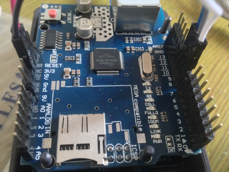
Hello! It looks like you're interested in this conversation, but you don't have an account yet.
Getting fed up of having to scroll through the same posts each visit? When you register for an account, you'll always come back to exactly where you were before, and choose to be notified of new replies (either via email, or push notification). You'll also be able to save bookmarks and upvote posts to show your appreciation to other community members.
With your input, this post could be even better 💗
Register Login