Ultra low temperature (-80ºC) monitoring probes
-
Digging a little more in the docs, it seems that most of these freezer have a "4-20mA" output port, and this one does. (for 250 Ohm loads)
I'm starting to find explanations on how this work, mostly for 24V non powered sensors and 5V arduino.
This freezer seems to use a 12V version, already powered. I now have ~12V between Pins 1 and 2, and there is a 7mA current going through while it's -82ºC.So my guess is that a simple voltage divider should do it, right?
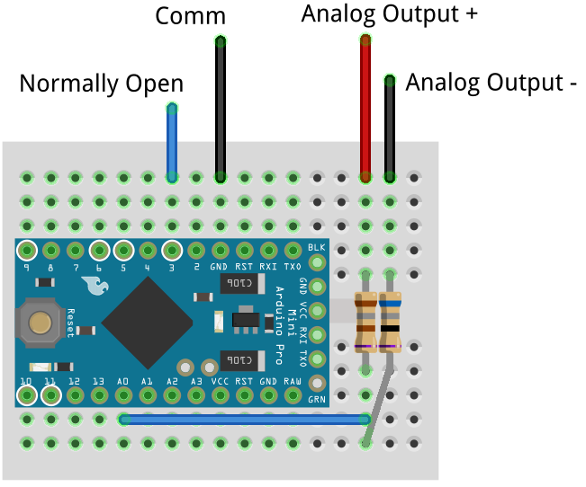
- Resistors are 182 and 68 ohms (250 Ohm total)
- I should have ~3.2V across R2 that can then be measured with A0 (forgot it on the schematic, Analog - and Arduino GND will be linked)
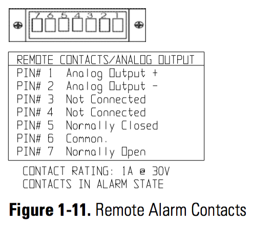
- Freezer also have a "normally open" contact, supposed to close when in alarm mode, so could use it as an Interrupt too.
I already have the temperature map: 4mA is -100ºC and 20mA is +50ºC so a
temp = map (AnalogRead(0), 0, 1023, -100, 50);should be pretty much it it code wise.
If anyone have experience on these things I'm listening (and googling) while waiting for the parts to come. At least then the MySensors part is easy to add!
@emc2
I would connect a 250 Ohm (standard 249 Ohm..) resistor from Analog Output (+) to GND (pro-mini). Connect the Analog (-) to GND (pro-mini) as well and a wire from Analog Output (+) to an A0.The 4-20 mA is 'pushed' through the 250 Ohm resistor which creates a voltage of 1VDC at 4 mA and 5 VDC at 20 mA (and of course any value in between). U=I*R
Under '4-20mA current loop' with your preferred search engine you will find lots of background information.
Change the temp map as follows:
temp = map (AnalogRead(0), 205, 1023, -100, 50); -
@boozz Yes that's what I found used for 5V arduino, that's why I broke my 250 ohm into a 182/68 divider.
The fact that at some point A0 may be connected to >3.3V is not a problem?Worst case scenario I can add a 3.3V regulator for the radio and use a 5V arduino.
-
@boozz Yes that's what I found used for 5V arduino, that's why I broke my 250 ohm into a 182/68 divider.
The fact that at some point A0 may be connected to >3.3V is not a problem?Worst case scenario I can add a 3.3V regulator for the radio and use a 5V arduino.
@emc2
I was not aware of the fact that a 3.3V pro-mini was used. Anyway, replace the 250 Ohm resistor in my post by a 165 Ohm resistor and the value on A0 will change between 205 and 1023.....165 = (3.3/5)*250
No need for a voltage divider in a 4-20mA current loop.
BR,
Boozz
-
@boozz everything seems to work.
I also realized that as the node will be battery powered, it may be better to use the 1.1V internal ref.
If I'm right a 47-55 Ohm resistor should be all what I need, as long as I'm also updating the map() upper scale (ex: use 930 instead of 1023 as I use a 50 Ohm then 20mA voltage will be 1V) -
@boozz everything seems to work.
I also realized that as the node will be battery powered, it may be better to use the 1.1V internal ref.
If I'm right a 47-55 Ohm resistor should be all what I need, as long as I'm also updating the map() upper scale (ex: use 930 instead of 1023 as I use a 50 Ohm then 20mA voltage will be 1V)In case someone ends up on this topic using the search function, PCB and code for using a 4-20mA sensor is available on https://forum.mysensors.org/topic/5508/mysfreezer
-
No I do not sell these assembled.
I think the only option on openhardware is DIY kit, but with the included Gerber files and BOM you should be able to have it assembled at a local fab house.For notifications, mine is actually linked to IFTTT using a script in domoticz, but basically you can use any notification functions used in your controller.
-
@sbpurohit I assume it comes with everything (else it would defeat the point of the kit), but I would suggest you to email PCBway to have direct confirmation with them.
Hello! It looks like you're interested in this conversation, but you don't have an account yet.
Getting fed up of having to scroll through the same posts each visit? When you register for an account, you'll always come back to exactly where you were before, and choose to be notified of new replies (either via email, or push notification). You'll also be able to save bookmarks and upvote posts to show your appreciation to other community members.
With your input, this post could be even better 💗
Register Login