Skip to content
  • MySensors
  • OpenHardware.io
  • Categories
  • Recent
  • Tags
  • Popular
Skins
  • Light
  • Brite
  • Cerulean
  • Cosmo
  • Flatly
  • Journal
  • Litera
  • Lumen
  • Lux
  • Materia
  • Minty
  • Morph
  • Pulse
  • Sandstone
  • Simplex
  • Sketchy
  • Spacelab
  • United
  • Yeti
  • Zephyr
  • Dark
  • Cyborg
  • Darkly
  • Quartz
  • Slate
  • Solar
  • Superhero
  • Vapor

  • Default (No Skin)
  • No Skin
Collapse
Brand Logo
  1. Home
  2. OpenHardware.io
  3. 💬 RFM69 Serial GW (ATMEGA328P)

💬 RFM69 Serial GW (ATMEGA328P)

Scheduled Pinned Locked Moved OpenHardware.io
mysensors gatewayserial
24 Posts 7 Posters 6.9k Views 6 Watching
  • Oldest to Newest
  • Newest to Oldest
  • Most Votes
Reply
  • Reply as topic
Log in to reply
This topic has been deleted. Only users with topic management privileges can see it.
  • mtiutiuM Offline
    mtiutiuM Offline
    mtiutiu
    Hardware Contributor
    wrote on last edited by
    #10

    Serial gw is working. Tested with real MySensors nodes and it's working properly. Now regarding stability and such - well...that only time will tell us.

    1 Reply Last reply
    0
    • tonnerre33T Offline
      tonnerre33T Offline
      tonnerre33
      Hardware Contributor
      wrote on last edited by
      #11

      Hello, what is the goal of the TXB0104, it's the first time that i see him in a project ?

      mtiutiuM 1 Reply Last reply
      0
      • tonnerre33T tonnerre33

        Hello, what is the goal of the TXB0104, it's the first time that i see him in a project ?

        mtiutiuM Offline
        mtiutiuM Offline
        mtiutiu
        Hardware Contributor
        wrote on last edited by
        #12

        @tonnerre33

        It's a logic level voltage converter. The MCU runs at 5V so the logic level voltage that it uses on the SPI port which connects to the RFM69W use 5V too. But the RFM69W module runs at 3.3V and it's not 5V tolerant on its SPI port pins.

        The purpose of that IC is to convert voltage levels on the SPI lines forward and backward (from 5V to 3.3V and vice versa) in order to not damage the RFM69W chip.

        tonnerre33T 1 Reply Last reply
        1
        • mtiutiuM mtiutiu

          @tonnerre33

          It's a logic level voltage converter. The MCU runs at 5V so the logic level voltage that it uses on the SPI port which connects to the RFM69W use 5V too. But the RFM69W module runs at 3.3V and it's not 5V tolerant on its SPI port pins.

          The purpose of that IC is to convert voltage levels on the SPI lines forward and backward (from 5V to 3.3V and vice versa) in order to not damage the RFM69W chip.

          tonnerre33T Offline
          tonnerre33T Offline
          tonnerre33
          Hardware Contributor
          wrote on last edited by tonnerre33
          #13

          @mtiutiu said in 💬 MySensors RFM69W serial GW(ATMEGA328P):

          Oh ok, and just for know, why we don't power the atmega with 3.3V ?

          mtiutiuM 1 Reply Last reply
          0
          • tonnerre33T tonnerre33

            @mtiutiu said in 💬 MySensors RFM69W serial GW(ATMEGA328P):

            Oh ok, and just for know, why we don't power the atmega with 3.3V ?

            mtiutiuM Offline
            mtiutiuM Offline
            mtiutiu
            Hardware Contributor
            wrote on last edited by mtiutiu
            #14

            @tonnerre33
            Because at 3.3V the atmega328p mcu can run at max 8MHz as per datasheet. So I wanted it to run at double the speed and for that it needs 5V as per datasheet again. Why at 16MHz? Well because I want the gateway to be more faster in general and to quickly process the incoming messages from the entire radio network.

            1 Reply Last reply
            1
            • tonnerre33T Offline
              tonnerre33T Offline
              tonnerre33
              Hardware Contributor
              wrote on last edited by
              #15

              Thanks a lot, now i know why ;)

              mtiutiuM 1 Reply Last reply
              0
              • tonnerre33T tonnerre33

                Thanks a lot, now i know why ;)

                mtiutiuM Offline
                mtiutiuM Offline
                mtiutiu
                Hardware Contributor
                wrote on last edited by
                #16

                @tonnerre33

                And to use higher baudrates for the serial port on the mcu also. To achieve higher baudrates you need a higher mcu clock frequency too.

                1 Reply Last reply
                0
                • S Offline
                  S Offline
                  shabba
                  wrote on last edited by
                  #17

                  Does anyone have a BOM for this?

                  mtiutiuM 1 Reply Last reply
                  0
                  • S shabba

                    Does anyone have a BOM for this?

                    mtiutiuM Offline
                    mtiutiuM Offline
                    mtiutiu
                    Hardware Contributor
                    wrote on last edited by mtiutiu
                    #18

                    @shabba
                    Sorry but I don't have one now. When I have time I will generate it. For now I'm busy with the Livolo stuff.

                    1 Reply Last reply
                    0
                    • tonnerre33T Offline
                      tonnerre33T Offline
                      tonnerre33
                      Hardware Contributor
                      wrote on last edited by
                      #19

                      0_1494000655324_upload-1cfecb9c-1343-4411-a8c4-b4546cd9a63e

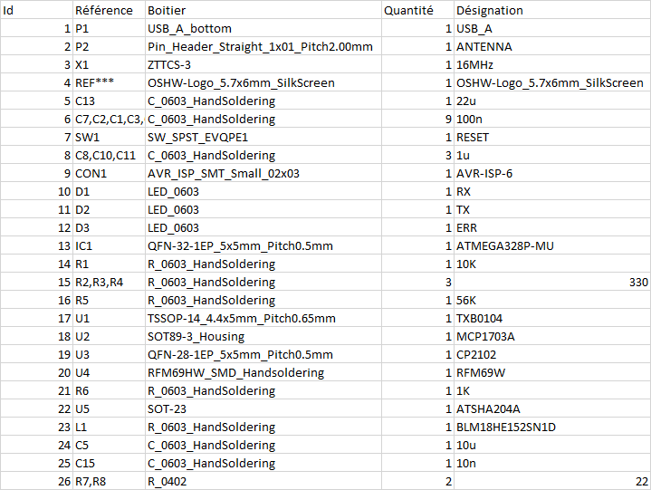
                      A fast extraction without traitment if that can help ;)

                      1 Reply Last reply
                      2
                      • S Offline
                        S Offline
                        shabba
                        wrote on last edited by
                        #20

                        I see C5 on the board has polarity. My ceramic caps seem to have no polarity (no markings on it - https://www.digikey.com/product-detail/en/murata-electronics-north-america/ZRB18AR61E106ME01L/490-10991-1-ND/5321192).
                        I assume that this is ok and this does not need to be a tantalum cap?

                        Thanks.

                        mtiutiuM 1 Reply Last reply
                        0
                        • S shabba

                          I see C5 on the board has polarity. My ceramic caps seem to have no polarity (no markings on it - https://www.digikey.com/product-detail/en/murata-electronics-north-america/ZRB18AR61E106ME01L/490-10991-1-ND/5321192).
                          I assume that this is ok and this does not need to be a tantalum cap?

                          Thanks.

                          mtiutiuM Offline
                          mtiutiuM Offline
                          mtiutiu
                          Hardware Contributor
                          wrote on last edited by mtiutiu
                          #21

                          @shabba

                          Yes it's ok. Just make sure that you have 10V rated capacitors(this board runs at 5V so it's best to stay above that). On the radio side you can use 6V capacitors as it's powered at 3.3V but anyway...it's easier to use just 10V types instead of remembering what goes where imho.

                          1 Reply Last reply
                          0
                          • S Offline
                            S Offline
                            shabba
                            wrote on last edited by
                            #22

                            Hi @mtiutiu - Did you ever get a chance to make a BOM? Most of the one @tonnerre33 one makes sense but I only bought two boards so being a little cautious :-)

                            Thanks!

                            1 Reply Last reply
                            1
                            • S Offline
                              S Offline
                              shabba
                              wrote on last edited by
                              #23

                              Any BOM? :-)
                              I still have these PCBs and want to finish em. Can't source a crystal/resonator of about 5x4 mm.

                              mtiutiuM 1 Reply Last reply
                              1
                              • S shabba

                                Any BOM? :-)
                                I still have these PCBs and want to finish em. Can't source a crystal/resonator of about 5x4 mm.

                                mtiutiuM Offline
                                mtiutiuM Offline
                                mtiutiu
                                Hardware Contributor
                                wrote on last edited by
                                #24

                                @shabba

                                The majority of the components are 0603 SMD package type (except 2 smd resistors on the usb lines which are not really mandatory and can be replaced with a solder bridge).

                                There you go (extracted from schematic - I can't do better than this because it involves more work and I don't have time for it, sorry):

                                a) 9 x 100nF 0603 SMD MLCC capacitors, X5R/X7R (voltage can be 10V and above)
                                b) 3 x 1uF 0603 SMD MLCC capacitors, X5R/X7R (voltage can be 10V and above)
                                c) 1 x 10uF 0603 SMD MLCC capacitor, X5R/X7R (voltage can be 10V and above)
                                d) 1 x 22uF 0603 SMD MLCC capacitor, X5R/X7R (voltage can be 10V and above)
                                e) 1 x 10nF 0603 SMD MLCC capacitor, X5R/X7R (voltage can be 10V and above)
                                f) 1 x ferrite bead 0603 SMD blm18he152sn1d
                                g) 3 x 330 ohm 0603 SMD resistor
                                h) 1 x 1Kohm 0603 SMD resistor
                                i) 1 x 10Kohm 0603 SMD resistor
                                j) 1 x 56Kohm 0603 SMD resistor
                                k) 1 x MCP1703A-3302 3.3V/0.25A voltage regulator
                                l) 1 x TXB0104 voltage level converter
                                m) 1 x ATMEGA328P-MU AVR MCU (QFN32 package)
                                n) 1 x CP2102 USB to serial (QFN28 package)
                                o) 3 x 0603 SMD LEDs (your pick here)
                                p) 1 x ATSHA204A (SOT-23 package)
                                q) 1 x RFM69W module (your pick regarding working frequency)
                                r) 1 x ZTTCS16.00MX ceramic resonator
                                s) 1 x USB A type male connector for PCB and 1 SMD reset switch (I have no exact links for this, sorry)

                                1 Reply Last reply
                                0
                                Reply
                                • Reply as topic
                                Log in to reply
                                • Oldest to Newest
                                • Newest to Oldest
                                • Most Votes


                                11

                                Online

                                11.7k

                                Users

                                11.2k

                                Topics

                                113.1k

                                Posts


                                Copyright 2025 TBD   |   Forum Guidelines   |   Privacy Policy   |   Terms of Service
                                • Login

                                • Don't have an account? Register

                                • Login or register to search.
                                • First post
                                  Last post
                                0
                                • MySensors
                                • OpenHardware.io
                                • Categories
                                • Recent
                                • Tags
                                • Popular