Dimmer sketches - array and multiple PWM led pins
-
hi,
this is what i use for 3 dimmers:/** * The MySensors Arduino library handles the wireless radio link and protocol * between your home built sensors/actuators and HA controller of choice. * The sensors forms a self healing radio network with optional repeaters. Each * repeater and gateway builds a routing tables in EEPROM which keeps track of the * network topology allowing messages to be routed to nodes. * * Created by Henrik Ekblad <henrik.ekblad@mysensors.org> * Copyright (C) 2013-2015 Sensnology AB * Full contributor list: https://github.com/mysensors/Arduino/graphs/contributors * * Documentation: http://www.mysensors.org * Support Forum: http://forum.mysensors.org * * This program is free software; you can redistribute it and/or * modify it under the terms of the GNU General Public License * version 2 as published by the Free Software Foundation. * ******************************* * * REVISION HISTORY * Version 1.0 - February 15, 2014 - Bruce Lacey * Version 1.1 - August 13, 2014 - Converted to 1.4 (hek) * * DESCRIPTION * This sketch provides a Dimmable LED Light using PWM and based Henrik Ekblad * <henrik.ekblad@gmail.com> Vera Arduino Sensor project. * Developed by Bruce Lacey, inspired by Hek's MySensor's example sketches. * * The circuit uses a MOSFET for Pulse-Wave-Modulation to dim the attached LED or LED strip. * The MOSFET Gate pin is connected to Arduino pin 3 (LED_PIN), the MOSFET Drain pin is connected * to the LED negative terminal and the MOSFET Source pin is connected to ground. * * This sketch is extensible to support more than one MOSFET/PWM dimmer per circuit. * http://www.mysensors.org/build/dimmer * * * LISTE DE POINTS: * D0 DISPO * D1 DISPO * D2 IRQ NRF * D3 LED1 * D4 DISPO * D5 LED2 * D6 LED3 * D7 DISPO * D8 DISPO * D9 CE NRF * D10 CSN/CS NRF * D11 MOSI NRF * D12 MISO NRF * D13 SCK NRF * D14 DISPO * * */ // Enable debug prints to serial monitor #define MY_DEBUG // Enable and select radio type attached #define MY_RADIO_NRF24 //#define MY_RADIO_RFM69 //#define MY_NODE_ID 153 #include <SPI.h> #include <MySensors.h> #define SN "BUREAU PARENTS" #define SV "1.2" #define noLEDs 3 const int LED_Pin[] = {3, 5, 6}; #define FADE_DELAY 10 // Delay in ms for each percentage fade up/down (10ms = 1s full-range dim) static int currentLevel1 = 0; // Current dim level... static int currentLevel2 = 0; // Current dim level... static int currentLevel3 = 0; // Current dim level... MyMessage dimmer1Msg(1, V_DIMMER); MyMessage light1Msg(1, V_LIGHT); MyMessage dimmer2Msg(2, V_DIMMER); MyMessage light2Msg(2, V_LIGHT); MyMessage dimmer3Msg(3, V_DIMMER); MyMessage light3Msg(3, V_LIGHT); /*** * Dimmable LED initialization method */ void setup() { // LEDS // Pull the gateway's current dim level - restore light level upon sendor node power-up for (int sensor=1; sensor<=noLEDs; sensor++){ request( sensor, V_DIMMER ); } } void presentation() { // Register the LED Dimmable Light with the gateway for (int sensor=1; sensor<=noLEDs; sensor++){ present(sensor, S_DIMMER); wait(2); } sendSketchInfo(SN, SV); } /*** * Dimmable LED main processing loop */ void loop() { } void receive(const MyMessage &message) { if (message.type == V_LIGHT || message.type == V_DIMMER) { if (message.sensor == 1) { // Retrieve the power or dim level from the incoming request message int requestedLevel1 = atoi( message.data ); // Adjust incoming level if this is a V_LIGHT variable update [0 == off, 1 == on] requestedLevel1 *= ( message.type == V_LIGHT ? 100 : 1 ); // Clip incoming level to valid range of 0 to 100 requestedLevel1 = requestedLevel1 > 100 ? 100 : requestedLevel1; requestedLevel1 = requestedLevel1 < 0 ? 0 : requestedLevel1; fadeToLevel1( requestedLevel1, message.sensor ); send(light1Msg.set(currentLevel1 > 0 ? 1 : 0)); send(dimmer1Msg.set(currentLevel1) );} if (message.sensor == 2) { // Retrieve the power or dim level from the incoming request message int requestedLevel2 = atoi( message.data ); // Adjust incoming level if this is a V_LIGHT variable update [0 == off, 1 == on] requestedLevel2 *= ( message.type == V_LIGHT ? 100 : 1 ); // Clip incoming level to valid range of 0 to 100 requestedLevel2 = requestedLevel2 > 100 ? 100 : requestedLevel2; requestedLevel2 = requestedLevel2 < 0 ? 0 : requestedLevel2; fadeToLevel2( requestedLevel2, message.sensor ); send(light2Msg.set(currentLevel2 > 0 ? 1 : 0)); send(dimmer2Msg.set(currentLevel2) );} if (message.sensor == 3) { // Retrieve the power or dim level from the incoming request message int requestedLevel3 = atoi( message.data ); // Adjust incoming level if this is a V_LIGHT variable update [0 == off, 1 == on] requestedLevel3 *= ( message.type == V_LIGHT ? 100 : 1 ); // Clip incoming level to valid range of 0 to 100 requestedLevel3 = requestedLevel3 > 100 ? 100 : requestedLevel3; requestedLevel3 = requestedLevel3 < 0 ? 0 : requestedLevel3; fadeToLevel3( requestedLevel3, message.sensor ); send(light3Msg.set(currentLevel3 > 0 ? 1 : 0)); send(dimmer3Msg.set(currentLevel3) );} } } /*** * This method provides a graceful fade up/down effect */ void fadeToLevel1( int toLevel1, int ledid1 ) { int delta1 = ( toLevel1 - currentLevel1 ) < 0 ? -1 : 1; while ( currentLevel1 != toLevel1 ) { currentLevel1 += delta1; analogWrite(LED_Pin[ledid1-1], (int)(currentLevel1 / 100. * 255) ); wait( FADE_DELAY ); } } void fadeToLevel2( int toLevel2, int ledid2 ) { int delta2 = ( toLevel2 - currentLevel2 ) < 0 ? -1 : 1; while ( currentLevel2 != toLevel2 ) { currentLevel2 += delta2; analogWrite(LED_Pin[ledid2-1], (int)(currentLevel2 / 100. * 255) ); wait( FADE_DELAY ); } } void fadeToLevel3( int toLevel3, int ledid3 ) { int delta3 = ( toLevel3 - currentLevel3 ) < 0 ? -1 : 1; while ( currentLevel3 != toLevel3 ) { currentLevel3 += delta3; analogWrite(LED_Pin[ledid3-1], (int)(currentLevel3 / 100. * 255) ); wait( FADE_DELAY ); } }it work not too bad, maybe that can help!
-
@MCF
Thanks for the sketch. It works pretty good. There is this one thing which is not working
It contains// Pull the gateway's current dim level - restore light level upon sendor node power-up for (int sensor=1; sensor<=noLEDs; sensor++){ request( sensor, V_DIMMER );I don't know why but it doesnt save the last dimming status. It's always on 100% after switching ON.
I was trying to implement in your sketch
saveState(EPROM_DIMMER_LEVEL, LastDimValue)but finished with nothing.
Still looking for solution ... :( -
After searching for a solution I finally stayed with code below.
// Enable debug prints
#define MY_DEBUG

// Enable and select radio type attached
#define MY_RADIO_NRF24
//#define MY_RADIO_RFM69

#define MY_RF24_CE_PIN 49
#define MY_RF24_CS_PIN 53

#include <SPI.h>
#include <MySensors.h>
#include <Bounce2.h>

#define CHILD_ID_LIGHT1 1

#define EPROM_LIGHT1_STATE 1
#define EPROM_DIMMER1_LEVEL 2

#define LIGHT1_OFF 0
#define LIGHT1_ON 1
#define SN "DimableMacio"
#define SV "1.0"

#define LED_PIN1 3
#define MAXDIMLEVELS                     100

//#define FADE_DELAY 10  // Delay in ms for each percentage fade up/down (10ms = 1s full-range dim)

int16_t LastLight1State=LIGHT1_OFF;
int16_t LastDim1Value=MAXDIMLEVELS;

//int dimlevels=100
int dimlevels[ MAXDIMLEVELS ] =  // PWM values used for translating home automation dimmer levels. This gives smoother transations
  {   0,   1,   2,   3,   4,   5,   6,   7,   8,   9,
     10,  11,  12,  13,  14,  15,  16,  17,  18,  19,
     20,  21,  22,  23,  24,  25,  26,  27,  28,  29,
     30,  31,  32,  35,  39,  42,  46,  49,  52,  56,
     59,  62,  66,  69,  73,  76,  79,  83,  86,  89,
     93,  96, 100, 103, 106, 110, 113, 116, 120, 123,
    126, 130, 133, 137, 140, 144, 147, 150, 154, 157,
    160, 164, 167, 171, 174, 177, 181, 184, 187, 191,
    194, 197, 201, 204, 208, 211, 215, 218, 221, 225,
    228, 231, 235, 238, 242, 245, 246, 250, 251, 255};


MyMessage light1Msg(CHILD_ID_LIGHT1, V_STATUS);
MyMessage dimmer1Msg(CHILD_ID_LIGHT1, V_PERCENTAGE);

void setup()
{
  //Retreive our last light 1 state from the eprom
  int Light1State=loadState(EPROM_LIGHT1_STATE);
  if (Light1State<=1) {
    LastLight1State=Light1State;
    int Dim1Value=loadState(EPROM_DIMMER1_LEVEL);
    if ((Dim1Value>0)&&(Dim1Value<=100)) {
      //There should be no Dim value of 0, this would mean LIGHT_OFF
      LastDim1Value=Dim1Value;
    }
  }

  //Here you actualy switch on/off the light 1 with the last known dim level
  SetCurrentState2Hardware1();
  Serial.println( "Node nr 1 ready to receive messages..." );
  }

void presentation() {
  // Register the LED Dimmable Light with the gateway
 //for (int sensor=1; sensor<=noLEDs; sensor++){
 present(CHILD_ID_LIGHT1, S_DIMMER);
 wait(2);
  sendSketchInfo(SN, SV);
  }

void loop()
{}

void receive(const MyMessage &message) {

  if (message.type == V_STATUS) {
    Serial.println( "V_STATUS LED1 command received..." );

    int lstate1= atoi( message.data );
    if ((lstate1<0)||(lstate1>1)) {
      Serial.println( "V_STATUS LED1 data invalid (should be 0/1)" );
      return;
    }
    LastLight1State=lstate1;
    saveState(EPROM_LIGHT1_STATE, LastLight1State);

    if ((LastLight1State==LIGHT1_ON)&&(LastDim1Value==0)) {
      //In the case that the Light State = On, but the dimmer value is zero,
      //then something (probably the controller) did something wrong,
      //for the Dim value to 100%
      LastDim1Value=100;
      saveState(EPROM_DIMMER1_LEVEL, LastDim1Value);
    }

    //When receiving a V_LIGHT command we switch the light between OFF and the last received dimmer value
    //This means if you previously set the lights dimmer value to 50%, and turn the light ON
    //it will do so at 50%
  } else if (message.type == V_PERCENTAGE) {
    Serial.println( "V_PERCENTAGE LED1 command received..." );
    int dim1value= atoi( message.data );
    if ((dim1value<0)||(dim1value>100)) {
      Serial.println( "V_PERCENTAGE LED1 data invalid (should be 0..100)" );
      return;
    }
    if (dim1value==0) {
      LastLight1State=LIGHT1_OFF;
    } else {
      LastLight1State=LIGHT1_ON;
      LastDim1Value=dim1value;
      saveState(EPROM_DIMMER1_LEVEL, LastDim1Value);
    }
  } else {
    Serial.println( "Invalid command received..." );
    return;
  }

  //Here you set the actual light state/level
  SetCurrentState2Hardware1();
}


void SetCurrentState2Hardware1()
{
  if (LastLight1State==LIGHT1_OFF) {
    analogWrite( LED_PIN1, dimlevels[0] );
    Serial.println( "Light state LED1: OFF" );
  } else {
    analogWrite( LED_PIN1, dimlevels[LastDim1Value-1] );
    Serial.println( dimlevels[LastDim1Value] );
    Serial.print( "Light state LED1: ON, Level: " );
    Serial.println( LastDim1Value );
  }

  //Send current state to the controller
  SendCurrentState2Controller1();
}

void SendCurrentState2Controller1()
{
  if ((LastLight1State==LIGHT1_OFF)||(LastDim1Value==0)) {
    send(dimmer1Msg.set((int16_t)0));
  } else {
    send(dimmer1Msg.set(LastDim1Value));
  }
}
Question to anybody who can help with the last annoying thing
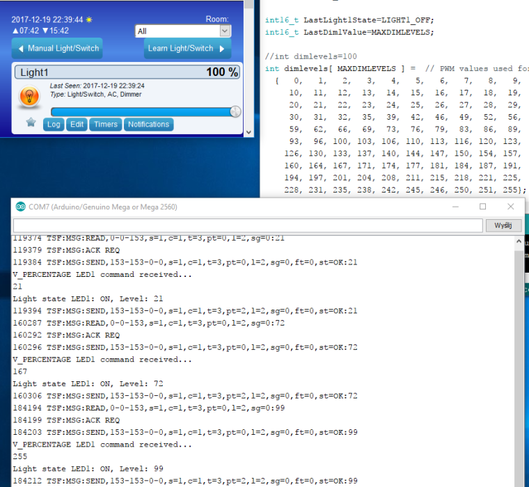
When I move the dimmer bar in Domoticz to a % value - arduino responds with the same % (for example 21% on the screen from serial monitor attached below)
BUT
When I move the dimmer bar to 100% - arduino responds with value of 99 - then it is forcing (sending back an info) to Domoticz and the value on the bar is chaning from 100% (set by me) to 99% forced by Arduino.
Question WHY ????????? 100% in Domoticz = 99% for Arduino ??????
Even changing this lineanalogWrite( LED_PIN1, dimlevels[LastDim1Value - 1] );and removing the (minus) still the same behavior (but I can see on the monitor I am pulling different values from array which is good)
PS. I tried to make the array bigger (like 101 cells and additional 255 value - still showing 99)
-
After searching for a solution I finally stayed with code below.
// Enable debug prints
#define MY_DEBUG

// Enable and select radio type attached
#define MY_RADIO_NRF24
//#define MY_RADIO_RFM69

#define MY_RF24_CE_PIN 49
#define MY_RF24_CS_PIN 53

#include <SPI.h>
#include <MySensors.h>
#include <Bounce2.h>

#define CHILD_ID_LIGHT1 1

#define EPROM_LIGHT1_STATE 1
#define EPROM_DIMMER1_LEVEL 2

#define LIGHT1_OFF 0
#define LIGHT1_ON 1
#define SN "DimableMacio"
#define SV "1.0"

#define LED_PIN1 3
#define MAXDIMLEVELS                     100

//#define FADE_DELAY 10  // Delay in ms for each percentage fade up/down (10ms = 1s full-range dim)

int16_t LastLight1State=LIGHT1_OFF;
int16_t LastDim1Value=MAXDIMLEVELS;

//int dimlevels=100
int dimlevels[ MAXDIMLEVELS ] =  // PWM values used for translating home automation dimmer levels. This gives smoother transations
  {   0,   1,   2,   3,   4,   5,   6,   7,   8,   9,
     10,  11,  12,  13,  14,  15,  16,  17,  18,  19,
     20,  21,  22,  23,  24,  25,  26,  27,  28,  29,
     30,  31,  32,  35,  39,  42,  46,  49,  52,  56,
     59,  62,  66,  69,  73,  76,  79,  83,  86,  89,
     93,  96, 100, 103, 106, 110, 113, 116, 120, 123,
    126, 130, 133, 137, 140, 144, 147, 150, 154, 157,
    160, 164, 167, 171, 174, 177, 181, 184, 187, 191,
    194, 197, 201, 204, 208, 211, 215, 218, 221, 225,
    228, 231, 235, 238, 242, 245, 246, 250, 251, 255};


MyMessage light1Msg(CHILD_ID_LIGHT1, V_STATUS);
MyMessage dimmer1Msg(CHILD_ID_LIGHT1, V_PERCENTAGE);

void setup()
{
  //Retreive our last light 1 state from the eprom
  int Light1State=loadState(EPROM_LIGHT1_STATE);
  if (Light1State<=1) {
    LastLight1State=Light1State;
    int Dim1Value=loadState(EPROM_DIMMER1_LEVEL);
    if ((Dim1Value>0)&&(Dim1Value<=100)) {
      //There should be no Dim value of 0, this would mean LIGHT_OFF
      LastDim1Value=Dim1Value;
    }
  }

  //Here you actualy switch on/off the light 1 with the last known dim level
  SetCurrentState2Hardware1();
  Serial.println( "Node nr 1 ready to receive messages..." );
  }

void presentation() {
  // Register the LED Dimmable Light with the gateway
 //for (int sensor=1; sensor<=noLEDs; sensor++){
 present(CHILD_ID_LIGHT1, S_DIMMER);
 wait(2);
  sendSketchInfo(SN, SV);
  }

void loop()
{}

void receive(const MyMessage &message) {

  if (message.type == V_STATUS) {
    Serial.println( "V_STATUS LED1 command received..." );

    int lstate1= atoi( message.data );
    if ((lstate1<0)||(lstate1>1)) {
      Serial.println( "V_STATUS LED1 data invalid (should be 0/1)" );
      return;
    }
    LastLight1State=lstate1;
    saveState(EPROM_LIGHT1_STATE, LastLight1State);

    if ((LastLight1State==LIGHT1_ON)&&(LastDim1Value==0)) {
      //In the case that the Light State = On, but the dimmer value is zero,
      //then something (probably the controller) did something wrong,
      //for the Dim value to 100%
      LastDim1Value=100;
      saveState(EPROM_DIMMER1_LEVEL, LastDim1Value);
    }

    //When receiving a V_LIGHT command we switch the light between OFF and the last received dimmer value
    //This means if you previously set the lights dimmer value to 50%, and turn the light ON
    //it will do so at 50%
  } else if (message.type == V_PERCENTAGE) {
    Serial.println( "V_PERCENTAGE LED1 command received..." );
    int dim1value= atoi( message.data );
    if ((dim1value<0)||(dim1value>100)) {
      Serial.println( "V_PERCENTAGE LED1 data invalid (should be 0..100)" );
      return;
    }
    if (dim1value==0) {
      LastLight1State=LIGHT1_OFF;
    } else {
      LastLight1State=LIGHT1_ON;
      LastDim1Value=dim1value;
      saveState(EPROM_DIMMER1_LEVEL, LastDim1Value);
    }
  } else {
    Serial.println( "Invalid command received..." );
    return;
  }

  //Here you set the actual light state/level
  SetCurrentState2Hardware1();
}


void SetCurrentState2Hardware1()
{
  if (LastLight1State==LIGHT1_OFF) {
    analogWrite( LED_PIN1, dimlevels[0] );
    Serial.println( "Light state LED1: OFF" );
  } else {
    analogWrite( LED_PIN1, dimlevels[LastDim1Value-1] );
    Serial.println( dimlevels[LastDim1Value] );
    Serial.print( "Light state LED1: ON, Level: " );
    Serial.println( LastDim1Value );
  }

  //Send current state to the controller
  SendCurrentState2Controller1();
}

void SendCurrentState2Controller1()
{
  if ((LastLight1State==LIGHT1_OFF)||(LastDim1Value==0)) {
    send(dimmer1Msg.set((int16_t)0));
  } else {
    send(dimmer1Msg.set(LastDim1Value));
  }
}
Question to anybody who can help with the last annoying thing
When I move the dimmer bar in Domoticz to a % value - arduino responds with the same % (for example 21% on the screen from serial monitor attached below)
BUT
When I move the dimmer bar to 100% - arduino responds with value of 99 - then it is forcing (sending back an info) to Domoticz and the value on the bar is chaning from 100% (set by me) to 99% forced by Arduino.
Question WHY ????????? 100% in Domoticz = 99% for Arduino ??????
Even changing this lineanalogWrite( LED_PIN1, dimlevels[LastDim1Value - 1] );and removing the (minus) still the same behavior (but I can see on the monitor I am pulling different values from array which is good)
PS. I tried to make the array bigger (like 101 cells and additional 255 value - still showing 99)
-
@dbemowsk
I am not sure what do You mean by numbers to percentage.
I've checked few different led dimmer sketches and all of them behave the same : You move the dimmer bar in Domoticz to 100% but the node receives a value of 99...
I've put the serial print to see the value (array) which is "delivered" to node.
I am writing to a LED pin value LastDimValue-1 but printing LastDim1Value which is then displayed next to the text ON,Level: ...
So again Domoticz bar 100% is displaying here a Level 99 ...analogWrite( LED_PIN1, dimlevels[LastDim1Value-1] ); Serial.println( dimlevels[LastDim1Value] );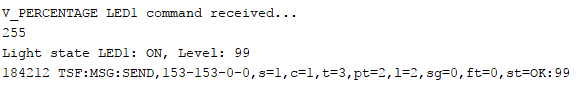
-
@dbemowsk
I am not sure what do You mean by numbers to percentage.
I've checked few different led dimmer sketches and all of them behave the same : You move the dimmer bar in Domoticz to 100% but the node receives a value of 99...
I've put the serial print to see the value (array) which is "delivered" to node.
I am writing to a LED pin value LastDimValue-1 but printing LastDim1Value which is then displayed next to the text ON,Level: ...
So again Domoticz bar 100% is displaying here a Level 99 ...analogWrite( LED_PIN1, dimlevels[LastDim1Value-1] ); Serial.println( dimlevels[LastDim1Value] ); -
@dbemowsk
Ok
Myself I dont make this conversion.
Unfortunately I dont know how the data exchange between Domoticz-Gateway-Node looks like.
I can see only the communication between Gateway-Node
In my case the dimming values are written in array.
Different way is to do it like this:analogWrite(LED_Pin[ledid1-1], (int)(currentLevel1 / 100. * 255) ) ; -
@dbemowsk
In the beggining of this topic there are two sketches. The 1st one is using the method which You've pasted. The 2nd one is using Array. I will test 1st one again today later but I'm sure I've tried it yesterday and it didnt work ( I mean still 100% from Domo was Level 99 for node.
Will test again and see where I am.
Thank You for now. -
So I'm back
1st sketch from this topic (with conversion) uploaded to Arduino...and still the same.
Have a look on my debug: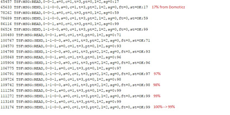
The last value was a 100% for like 2 seconds - then forced to be 99% and staying like this.
I don't know , maybe I am trying to get something impossible ?!? -
So I'm back
1st sketch from this topic (with conversion) uploaded to Arduino...and still the same.
Have a look on my debug:
The last value was a 100% for like 2 seconds - then forced to be 99% and staying like this.
I don't know , maybe I am trying to get something impossible ?!? -
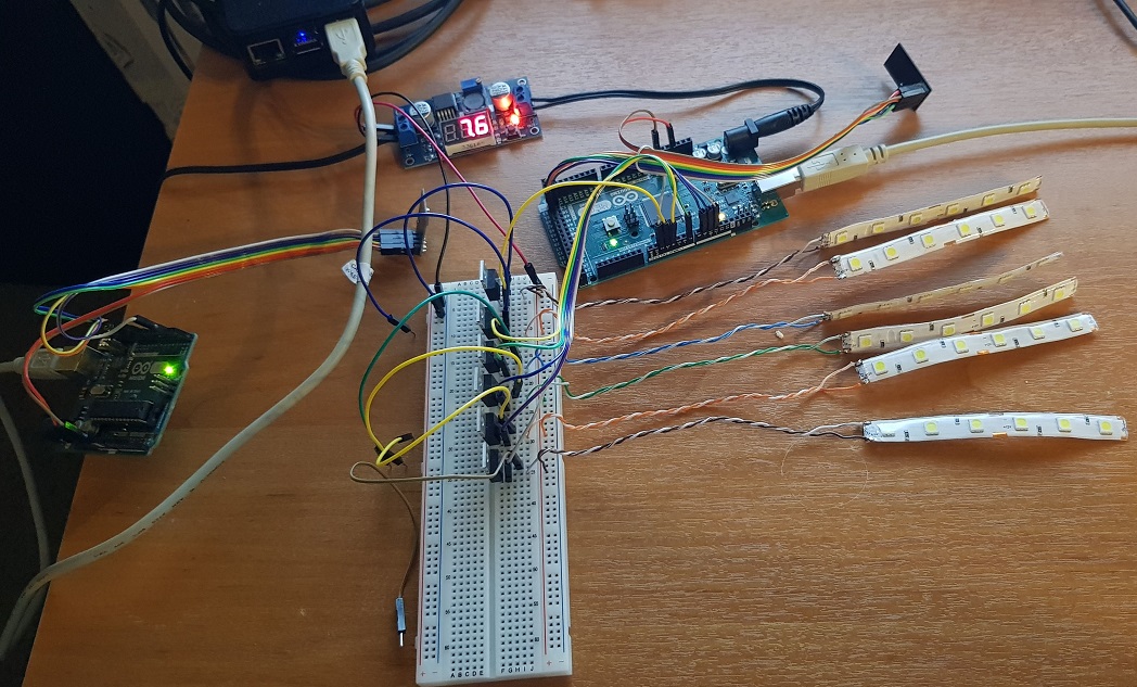
This is what I use for multiple sensors on one board. It is connected to a Home Assistant instance and seems to work for me.
(I am not using any radios, the uno is connected via usb to my rpi running HA, so the radio thingies are missing from the sketch)
#define MY_GATEWAY_SERIAL

#include <SPI.h>
#include <MySensors.h>
#include <DHT.h>

#define SN "LivingRoom"
#define SV "2.0"

//Only pins 2 and 3 can be used as motion sensors, because these generate interrupts
const int HCSR501S = 2;
int HCSR501_PINS[HCSR501S] = {2, 3};
int HCSR501_CHILD_IDS[HCSR501S] = {2, 3};

//DHTs
const int DHTS = 5;
int DHT_PINS[DHTS] = {4, 7, 8, 12, 13};
int DHT_TEMP_CHILD_IDS[DHTS] = {4, 5, 6, 7, 8};
int DHT_HUM_CHILD_IDS[DHTS] = {14, 15, 16, 17, 18};

//LED - Mosfet
const int LEDS = 5;
int LED_PINS[LEDS] = {5, 6, 9, 10, 11};
int LED_CHILD_IDS[LEDS] = {31, 32, 33, 34, 35};

#define FADE_DELAY 40  // Delay in ms for each percentage fade up/down (10ms = 1s full-range dim)
int WaitTime = 20;
static int16_t currentLevel[LEDS] = {0, 0, 0, 0, 0};
int requestedLevel[LEDS];

bool metric = true;
// Must be >1000ms for DHT22 and >2000ms for DHT11
//static const uint64_t UPDATE_INTERVAL = 60000;
static const uint64_t UPDATE_INTERVAL = 6000;
static bool first_message_sent = false;

MyMessage moveMsg0(HCSR501_CHILD_IDS[0], V_TRIPPED);
MyMessage moveMsg1(HCSR501_CHILD_IDS[1], V_TRIPPED);
//
MyMessage dimmerMsg0(LED_CHILD_IDS[0], V_DIMMER);
MyMessage lightMsg0(LED_CHILD_IDS[0], V_LIGHT);

MyMessage dimmerMsg1(LED_CHILD_IDS[1], V_DIMMER);
MyMessage lightMsg1(LED_CHILD_IDS[1], V_LIGHT);

MyMessage dimmerMsg2(LED_CHILD_IDS[2], V_DIMMER);
MyMessage lightMsg2(LED_CHILD_IDS[2], V_LIGHT);

MyMessage dimmerMsg3(LED_CHILD_IDS[3], V_DIMMER);
MyMessage lightMsg3(LED_CHILD_IDS[3], V_LIGHT);

MyMessage dimmerMsg4(LED_CHILD_IDS[4], V_DIMMER);
MyMessage lightMsg4(LED_CHILD_IDS[4], V_LIGHT);
//
MyMessage tempMsg0(DHT_TEMP_CHILD_IDS[0], V_TEMP);
MyMessage humMsg0(DHT_HUM_CHILD_IDS[0], V_HUM);

MyMessage tempMsg1(DHT_TEMP_CHILD_IDS[1], V_TEMP);
MyMessage humMsg1(DHT_HUM_CHILD_IDS[1], V_HUM);

MyMessage tempMsg2(DHT_TEMP_CHILD_IDS[2], V_TEMP);
MyMessage humMsg2(DHT_HUM_CHILD_IDS[2], V_HUM);

MyMessage tempMsg3(DHT_TEMP_CHILD_IDS[3], V_TEMP);
MyMessage humMsg3(DHT_HUM_CHILD_IDS[3], V_HUM);

MyMessage tempMsg4(DHT_TEMP_CHILD_IDS[4], V_TEMP);
MyMessage humMsg4(DHT_HUM_CHILD_IDS[4], V_HUM);
//
DHT dht1;
DHT dht2;
DHT dht3;
DHT dht4;
DHT dht5;

void before() {
  for (int i = 0; i < HCSR501S; i++) {
    pinMode(HCSR501_PINS[i], INPUT);
  }
  for (int q = 0; q < LEDS; q++) {
    pinMode(LED_PINS[q], OUTPUT);
  }
}

void setup()
{
  dht1.setup(DHT_PINS[0]);
  dht2.setup(DHT_PINS[1]);
  dht3.setup(DHT_PINS[2]);
  dht4.setup(DHT_PINS[3]);
  dht5.setup(DHT_PINS[4]);
  for (int q = 0; q < LEDS; q++) {
    request(LED_CHILD_IDS[q], V_DIMMER);
  }
}

void presentation() {
  sendSketchInfo(SN, SV);
  for (int i = 0; i < HCSR501S; i++) {
    present(HCSR501_CHILD_IDS[i], S_MOTION);
    wait(WaitTime);
  }
  for (int q = 0; q < DHTS; q++) {
    present(DHT_TEMP_CHILD_IDS[q], S_TEMP);
    wait(WaitTime);
    present(DHT_HUM_CHILD_IDS[q], S_HUM);
    wait(WaitTime);
  }
  for (int w = 0; w < LEDS; w++) {
    present(LED_CHILD_IDS[w], S_DIMMER);
    wait(WaitTime);
  }
}

void loop() {
  dht1.readSensor(true);
  dht2.readSensor(true);
  dht3.readSensor(true);
  dht4.readSensor(true);
  dht5.readSensor(true);
  //
  float temperature[DHTS];
  float humidity[DHTS];
  temperature[0] = dht1.getTemperature();
  humidity[0] = dht1.getHumidity();

  temperature[1] = dht2.getTemperature();
  humidity[1] = dht2.getHumidity();

  temperature[2] = dht3.getTemperature();
  humidity[2] = dht3.getHumidity();

  temperature[3] = dht4.getTemperature();
  humidity[3] = dht4.getHumidity();

  temperature[4] = dht5.getTemperature();
  humidity[4] = dht5.getHumidity();
  //
  send(tempMsg0.set(temperature[0], 1));
  send(humMsg0.set(humidity[0], 1));

  send(tempMsg1.set(temperature[1], 1));
  send(humMsg1.set(humidity[1], 1));

  send(tempMsg2.set(temperature[2], 1));
  send(humMsg2.set(humidity[2], 1));

  send(tempMsg3.set(temperature[3], 1));
  send(humMsg3.set(humidity[3], 1));

  send(tempMsg4.set(temperature[4], 1));
  send(humMsg4.set(humidity[4], 1));

  int tripped[HCSR501S];
  for (int i = 0; i < HCSR501S; i++) {
    tripped[i] = digitalRead(HCSR501_PINS[i]) == HIGH;
    send(moveMsg0.set(tripped[0] ? 1 : 0));
    send(moveMsg1.set(tripped[1] ? 1 : 0));
  }

  if ( first_message_sent == false ) {
    send(lightMsg0.set(currentLevel[0] > 0));
    send(dimmerMsg0.set(currentLevel[0]));

    send(lightMsg1.set(currentLevel[1] > 0));
    send(dimmerMsg1.set(currentLevel[1]));

    send(lightMsg2.set(currentLevel[2] > 0));
    send(dimmerMsg2.set(currentLevel[2]));

    send(lightMsg3.set(currentLevel[3] > 0));
    send(dimmerMsg3.set(currentLevel[3]));

    send(lightMsg4.set(currentLevel[4] > 0));
    send(dimmerMsg4.set(currentLevel[4]));

    first_message_sent = true;
  }

  wait(UPDATE_INTERVAL);
}


void receive(const MyMessage &message) {
  int whichPIN = -1;
  int whichID = -1;
  int whichITEM = -1;

  if (message.type == V_LIGHT || message.type == V_DIMMER) {
    for (int w = 0; w < LEDS; w++) {
      if (message.sensor == LED_CHILD_IDS[w]) {
        whichPIN = LED_PINS[w];
        whichID = LED_CHILD_IDS[w];
        whichITEM = w;
        break;
      }
    }
    if (whichITEM > -1) {
      requestedLevel[whichITEM] = atoi( message.data );
      // Adjust incoming level if this is a V_LIGHT variable update [0 == off, 1 == on]
      requestedLevel[whichITEM] *= ( message.type == V_LIGHT ? 0 : 1 );
      requestedLevel[whichITEM] = requestedLevel[whichITEM] > 100 ? 100 : requestedLevel[whichITEM];
      requestedLevel[whichITEM] = requestedLevel[whichITEM] < 0   ? 0   : requestedLevel[whichITEM];

      int delta = ( requestedLevel[whichITEM] - currentLevel[whichITEM] ) < 0 ? -1 : 1;
      while ( currentLevel[whichITEM] != requestedLevel[whichITEM] ) {
        currentLevel[whichITEM] += delta;
        analogWrite( whichPIN, (int)(currentLevel[whichITEM] / 100. * 255) );
        delay( FADE_DELAY );
      }
      if (whichITEM == 0){
        send(lightMsg0.set(currentLevel[whichITEM] > 0));
        send(dimmerMsg0.set(currentLevel[whichITEM]));
      }
      if (whichITEM == 1){
        send(lightMsg1.set(currentLevel[whichITEM] > 0));
        send(dimmerMsg1.set(currentLevel[whichITEM]));
      }
      if (whichITEM == 2){
        send(lightMsg2.set(currentLevel[whichITEM] > 0));
        send(dimmerMsg2.set(currentLevel[whichITEM]));
      }
      if (whichITEM == 3){
        send(lightMsg3.set(currentLevel[whichITEM] > 0));
        send(dimmerMsg3.set(currentLevel[whichITEM]));
      }
      if (whichITEM == 4){
        send(lightMsg4.set(currentLevel[whichITEM] > 0));
        send(dimmerMsg4.set(currentLevel[whichITEM]));
      }
    }
  }
}```

Maybe this helps...
cheers
tom
Hello! It looks like you're interested in this conversation, but you don't have an account yet.
Getting fed up of having to scroll through the same posts each visit? When you register for an account, you'll always come back to exactly where you were before, and choose to be notified of new replies (either via email, or push notification). You'll also be able to save bookmarks and upvote posts to show your appreciation to other community members.
With your input, this post could be even better 💗
Register Login