Water Sensor
-
@hard-shovel said in Water Sensor:
Wow! Thank you! You just made a lot of stuff clear.
On the upper left part of the pannel - is actually a status LED. Which turns red when no water detected and green when it is. So i believe i should just dump the idea of getting anything from the water sensor and turn my view on the LED? This is the backside of the board.
AC is totally confusing me. Especially the LED part. When trying to measure ac voltage with my multimeter i have seen something like 30V between the live neutral and one of the LED legs. So any recommendation is very appreciated
@moskovskiy82 See if you can feed an optocoupler off of the LED.
-
@moskovskiy82 See if you can feed an optocoupler off of the LED.
Ok took the measurements once again on the led. This time measuriong only LED pins and not the live neutral wire. Between 1 and 3 gave me 0,1AC and 1,8DC when red and 0,1AC and 0,1DC when green. So just connected the anlogue pin of arduino to pin3 of LED and it works. Readings 19-70 when red led turned on. And 0-3 when off.
Just wonder how this led works from AC and is it still a good advice to put optocoupler into it? -
The Led is not actualy runing on AC. Part of the IC generates an low voltage AC signal (Nothing to do Mains Power) then other parts of the IC detect changes to this signal via the pair of diodes at the bottom, and then generate the two signals for the red and green leds.
The bicolor color led has a common terminal in the center and the two outer pins control the two outer pins power the red and green leds.
Utilizing a optocoupler has a safety advantage, as it isolates the power on the sensed unit from the mysensor node. It also allows systems using different control signal voltages to be interconnected.
If you have the arduino analogue pin connected to Pin3, where do you have the arduino GND connected?
As there is a relay that is connected in parallel to the the Upper LED drive transistor,
I recommend using a optocoupler and resistor connected to the relay terminals shown, as these connections are easy to solder wires to.
The resistor will need to be sized to match the voltage on the relay to limit current through the optocoupler led.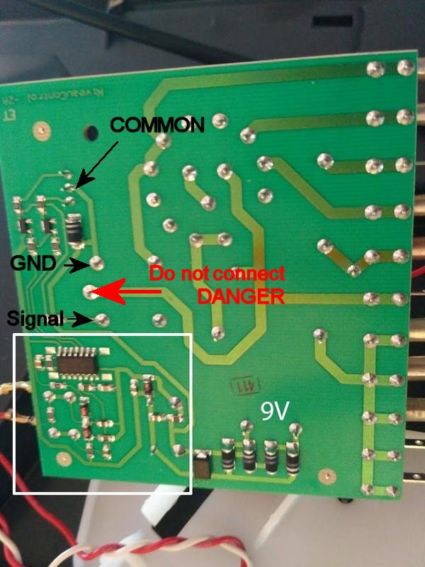
-
Ok took the measurements once again on the led. This time measuriong only LED pins and not the live neutral wire. Between 1 and 3 gave me 0,1AC and 1,8DC when red and 0,1AC and 0,1DC when green. So just connected the anlogue pin of arduino to pin3 of LED and it works. Readings 19-70 when red led turned on. And 0-3 when off.
Just wonder how this led works from AC and is it still a good advice to put optocoupler into it?@moskovskiy82 that LED is a bicolored LED. The center pin is common, and then one outer pin controls red, and the other controls green.
-
The Led is not actualy runing on AC. Part of the IC generates an low voltage AC signal (Nothing to do Mains Power) then other parts of the IC detect changes to this signal via the pair of diodes at the bottom, and then generate the two signals for the red and green leds.
The bicolor color led has a common terminal in the center and the two outer pins control the two outer pins power the red and green leds.
Utilizing a optocoupler has a safety advantage, as it isolates the power on the sensed unit from the mysensor node. It also allows systems using different control signal voltages to be interconnected.
If you have the arduino analogue pin connected to Pin3, where do you have the arduino GND connected?
As there is a relay that is connected in parallel to the the Upper LED drive transistor,
I recommend using a optocoupler and resistor connected to the relay terminals shown, as these connections are easy to solder wires to.
The resistor will need to be sized to match the voltage on the relay to limit current through the optocoupler led.@hard-shovel said in Water Sensor:
If you have the arduino analogue pin connected to Pin3, where do you have the arduino GND connected?
Well actually nowhere :) Thought that as the analogue pin is pulled to ground that will suffice.
Was happy at first but still seems the readings are erratic. So will follow your great advice with the optocoupler.
Do i get the connection scheme correctly?
-
@neverdie Do o really need the TLP222A as i already have 4N35 lying around
-
I'll withdraw the suggestion. I don't know what's right for you.
-
The TLP222A are opto-Mosfet devices so ideal for powering LEDs and small Relays etc as they have a 500mA rating, and the price listed is good value.
However for your application, use the 4N35 that you already have.
Your diagram is reversed as you need to drive the led in the optocoupler from the relay coil connections.Use the existing 10K as a pullup resistor at the input to the arduino,
On the relay side use a series resistor R1 of about 1Kohm for 12Vdc (expected from a 9Vac supply).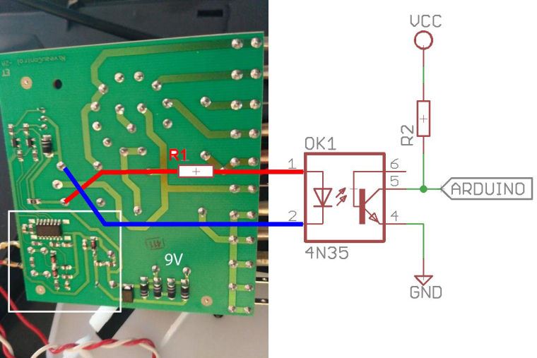
-
@hard-shovel said in Water Sensor:
Your diagram is reversed as you need to drive the led in the optocoupler from the relay coil connections.
Your ingenious scheme worked like a charm. Thank you!
Don't want to push but in such a rare possibility when you have access to such a marvelous help...The fan is of asynchronous type with 3 wires (neutral and 2 speeds). Currently i have just connected the output for speed1 to relay NC contact and speed2 to fan to NO contact. So it looks like this.

With such connection i still have the manual switch to off - 1st speed. But with such connection i cannot use manual switch on humidifier to choose the second switch. I have already use a multi meter to find out contacts
i was thinking of making my sensors node completely parallel to the board and use 4n35 to sense 220V AC on different rotary switch positions and drive relays appropriately. All the schematics i found on the web use bridge rectifier. Wonder if there is any way to go without one - and if not - what to order from aliexpress?
-
To sense the 220V without a bridge rectifer use an ac version of the opto-isolator, The optocoupler will still need the rest of the components ie resistors and/or capacitors.
typical types are H11AA1 or LTV814 etc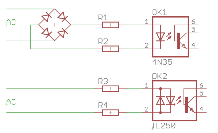
-
To sense the 220V without a bridge rectifer use an ac version of the opto-isolator, The optocoupler will still need the rest of the components ie resistors and/or capacitors.
typical types are H11AA1 or LTV814 etc@hard-shovel said in Water Sensor:
typical types are H11AA1 or LTV814 etc
Thank you! Seems like the best way to for me than. Will order and wait for them to arrive
Hello! It looks like you're interested in this conversation, but you don't have an account yet.
Getting fed up of having to scroll through the same posts each visit? When you register for an account, you'll always come back to exactly where you were before, and choose to be notified of new replies (either via email, or push notification). You'll also be able to save bookmarks and upvote posts to show your appreciation to other community members.
With your input, this post could be even better 💗
Register Login