Trouble wiring a Dalla 18B20 to Arduino D1 Mini
-
@zboblamont Power from 25 is going through the resistor to 22. The guide I followed stated that the center pin on the 18B20 can do power and data, so ground is shorted to Vdd, and power and data are both on the center pin. Maybe that's incorrect? I can try moving the jumper though as you described and see what happens.
@sirzlimz
Nothing wrong with the wiring. As @zboblamont already stated you've used the parasitic mode.
All my DS18B20's are connected that way (using pro-mini's).Any code available?
BR,
Boozz
-
@sirzlimz
Nothing wrong with the wiring. As @zboblamont already stated you've used the parasitic mode.
All my DS18B20's are connected that way (using pro-mini's).Any code available?
BR,
Boozz
-
@sirzlimz
Nothing wrong with the wiring. As @zboblamont already stated you've used the parasitic mode.
All my DS18B20's are connected that way (using pro-mini's).Any code available?
BR,
Boozz
@boozz ```
#include <SPI.h>
//#include <MySensors.h>
#include <OneWire.h>
#include <DallasTemperature.h>// Data wire is plugged into pin 2 on the Arduino
#define ONE_WIRE_BUS 2// Setup a oneWire instance to communicate with any OneWire devices
// (not just Maxim/Dallas temperature ICs)
OneWire oneWire(ONE_WIRE_BUS);// Pass our oneWire reference to Dallas Temperature.
DallasTemperature sensors(&oneWire);void setup(void)
{
// start serial port
Serial.begin(9600);
Serial.println("Dallas Temperature IC Control Library Demo");pinMode(2,INPUT);
// Start up the library
sensors.begin();
}void loop(void)
{
// call sensors.requestTemperatures() to issue a global temperature
// request to all devices on the bus
Serial.print(" Requesting temperatures...");
sensors.requestTemperatures(); // Send the command to get temperatures
Serial.println("DONE");Serial.print("Temperature for Device 1 is: ");
Serial.print(sensors.getTempCByIndex(0)); // Why "byIndex"?
// You can have more than one IC on the same bus.
// 0 refers to the first IC on the wire}```
-
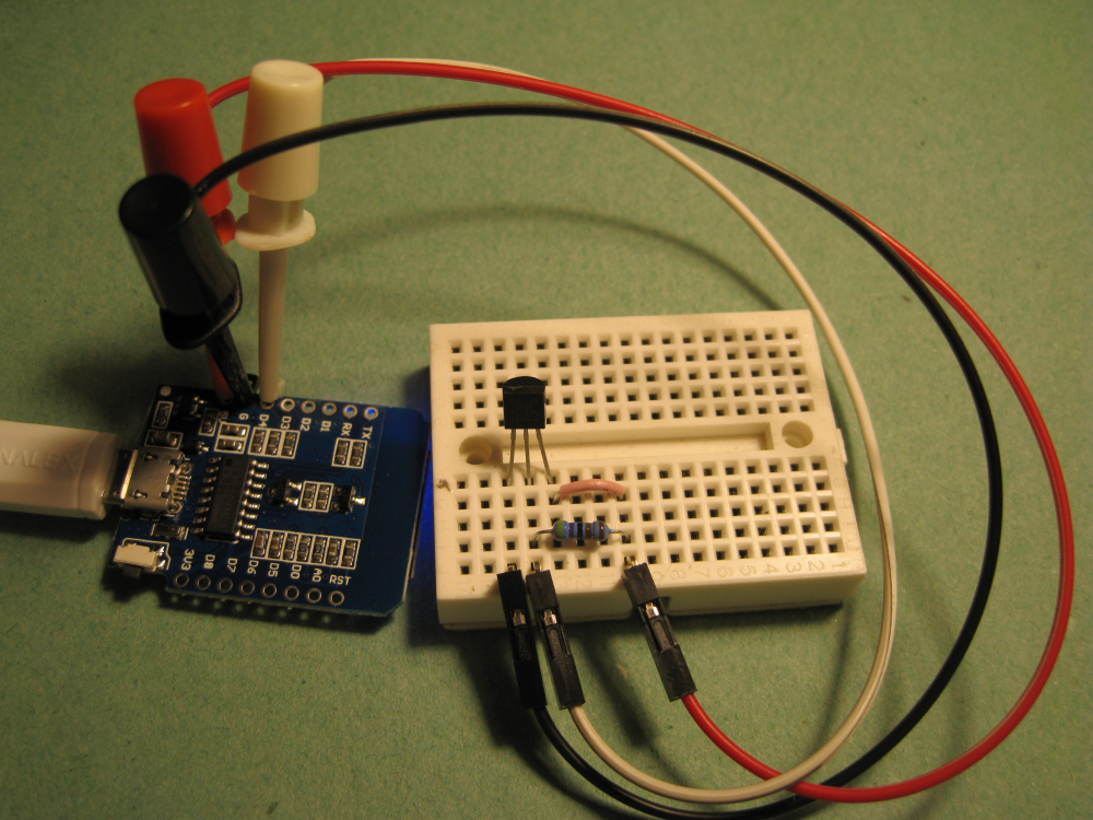
@sirzlimz There are two ways to use these devices, the method I found reliable was providing Vdd with power, and power via the drop resistor to the DQ pin (data).
I suggest trying the direct power method by pulling the jumper from line 21 and stick it into 25.
If it works fine, then try disconnecting to observe any difference.Forgot to say - The configuration you have is called Parasitic Mode, some leave Vdd dead ended, some short ground and Vdd together...
-
@zboblamont Moved yellow jumper from 21 to 25 as suggested and I'm still getting -127.00 on each line. Any other ideas?
@sirzlimz I should explain that I have 12 of these devices daisy chained and addressed as a table of chip addresses, the direct power method is reliable and power efficient for such an arrangement, hence my preference.
If you first check with a multimeter you are getting voltage at the Vdd and DQ pins it will first confirm you don't have a bad contact somewhere.
Attached is a test script I used to establish chip addresses to a pro-mini, just needs the pin changed at OneWire ds (XX) to suit your own.#include <OneWire.h> // OneWire DS18S20, DS18B20, DS1822 Temperature Example // // http://www.pjrc.com/teensy/td_libs_OneWire.html // // The DallasTemperature library can do all this work for you! // http://milesburton.com/Dallas_Temperature_Control_Library OneWire ds(16); // on signal pin (a single 4.7K resistor is necessary) void setup(void) { Serial.begin(9600); } void loop(void) { byte i; byte present = 0; byte type_s; byte data[12]; byte addr[8]; float celsius, fahrenheit; if ( !ds.search(addr)) { Serial.println("No more addresses."); Serial.println(); ds.reset_search(); delay(250); return; } Serial.print("ROM ="); for( i = 0; i < 8; i++) { Serial.write(' '); Serial.print(addr[i], HEX); } if (OneWire::crc8(addr, 7) != addr[7]) { Serial.println("CRC is not valid!"); return; } Serial.println(); // the first ROM byte indicates which chip switch (addr[0]) { case 0x10: Serial.println(" Chip = DS18S20"); // or old DS1820 type_s = 1; break; case 0x28: Serial.println(" Chip = DS18B20"); type_s = 0; break; case 0x22: Serial.println(" Chip = DS1822"); type_s = 0; break; default: Serial.println("Device is not a DS18x20 family device."); return; } ds.reset(); ds.select(addr); ds.write(0x44, 1); // start conversion, with parasite power on at the end delay(1000); // maybe 750ms is enough, maybe not // we might do a ds.depower() here, but the reset will take care of it. present = ds.reset(); ds.select(addr); ds.write(0xBE); // Read Scratchpad Serial.print(" Data = "); Serial.print(present, HEX); Serial.print(" "); for ( i = 0; i < 9; i++) { // we need 9 bytes data[i] = ds.read(); Serial.print(data[i], HEX); Serial.print(" "); } Serial.print(" CRC="); Serial.print(OneWire::crc8(data, 8), HEX); Serial.println(); // Convert the data to actual temperature // because the result is a 16 bit signed integer, it should // be stored to an "int16_t" type, which is always 16 bits // even when compiled on a 32 bit processor. int16_t raw = (data[1] << 8) | data[0]; if (type_s) { raw = raw << 3; // 9 bit resolution default if (data[7] == 0x10) { // "count remain" gives full 12 bit resolution raw = (raw & 0xFFF0) + 12 - data[6]; } } else { byte cfg = (data[4] & 0x60); // at lower res, the low bits are undefined, so let's zero them if (cfg == 0x00) raw = raw & ~7; // 9 bit resolution, 93.75 ms else if (cfg == 0x20) raw = raw & ~3; // 10 bit res, 187.5 ms else if (cfg == 0x40) raw = raw & ~1; // 11 bit res, 375 ms //// default is 12 bit resolution, 750 ms conversion time } celsius = (float)raw / 16.0; fahrenheit = celsius * 1.8 + 32.0; Serial.print(" Temperature = "); Serial.print(celsius); Serial.print(" Celsius, "); Serial.print(fahrenheit); Serial.println(" Fahrenheit"); }Hopefully it will help...
-
@sirzlimz I should explain that I have 12 of these devices daisy chained and addressed as a table of chip addresses, the direct power method is reliable and power efficient for such an arrangement, hence my preference.
If you first check with a multimeter you are getting voltage at the Vdd and DQ pins it will first confirm you don't have a bad contact somewhere.
Attached is a test script I used to establish chip addresses to a pro-mini, just needs the pin changed at OneWire ds (XX) to suit your own.#include <OneWire.h> // OneWire DS18S20, DS18B20, DS1822 Temperature Example // // http://www.pjrc.com/teensy/td_libs_OneWire.html // // The DallasTemperature library can do all this work for you! // http://milesburton.com/Dallas_Temperature_Control_Library OneWire ds(16); // on signal pin (a single 4.7K resistor is necessary) void setup(void) { Serial.begin(9600); } void loop(void) { byte i; byte present = 0; byte type_s; byte data[12]; byte addr[8]; float celsius, fahrenheit; if ( !ds.search(addr)) { Serial.println("No more addresses."); Serial.println(); ds.reset_search(); delay(250); return; } Serial.print("ROM ="); for( i = 0; i < 8; i++) { Serial.write(' '); Serial.print(addr[i], HEX); } if (OneWire::crc8(addr, 7) != addr[7]) { Serial.println("CRC is not valid!"); return; } Serial.println(); // the first ROM byte indicates which chip switch (addr[0]) { case 0x10: Serial.println(" Chip = DS18S20"); // or old DS1820 type_s = 1; break; case 0x28: Serial.println(" Chip = DS18B20"); type_s = 0; break; case 0x22: Serial.println(" Chip = DS1822"); type_s = 0; break; default: Serial.println("Device is not a DS18x20 family device."); return; } ds.reset(); ds.select(addr); ds.write(0x44, 1); // start conversion, with parasite power on at the end delay(1000); // maybe 750ms is enough, maybe not // we might do a ds.depower() here, but the reset will take care of it. present = ds.reset(); ds.select(addr); ds.write(0xBE); // Read Scratchpad Serial.print(" Data = "); Serial.print(present, HEX); Serial.print(" "); for ( i = 0; i < 9; i++) { // we need 9 bytes data[i] = ds.read(); Serial.print(data[i], HEX); Serial.print(" "); } Serial.print(" CRC="); Serial.print(OneWire::crc8(data, 8), HEX); Serial.println(); // Convert the data to actual temperature // because the result is a 16 bit signed integer, it should // be stored to an "int16_t" type, which is always 16 bits // even when compiled on a 32 bit processor. int16_t raw = (data[1] << 8) | data[0]; if (type_s) { raw = raw << 3; // 9 bit resolution default if (data[7] == 0x10) { // "count remain" gives full 12 bit resolution raw = (raw & 0xFFF0) + 12 - data[6]; } } else { byte cfg = (data[4] & 0x60); // at lower res, the low bits are undefined, so let's zero them if (cfg == 0x00) raw = raw & ~7; // 9 bit resolution, 93.75 ms else if (cfg == 0x20) raw = raw & ~3; // 10 bit res, 187.5 ms else if (cfg == 0x40) raw = raw & ~1; // 11 bit res, 375 ms //// default is 12 bit resolution, 750 ms conversion time } celsius = (float)raw / 16.0; fahrenheit = celsius * 1.8 + 32.0; Serial.print(" Temperature = "); Serial.print(celsius); Serial.print(" Celsius, "); Serial.print(fahrenheit); Serial.println(" Fahrenheit"); }Hopefully it will help...
@zboblamont So I'm looking for voltage across Vdd and DQ, or from ground to each? I have between 4.6-5V between Vdd and ground, and 3.something from Vdd to DQ I believe. Sorry, trying to recall from last night when I checked. I'll give that code a try tonight.
-
@zboblamont So I'm looking for voltage across Vdd and DQ, or from ground to each? I have between 4.6-5V between Vdd and ground, and 3.something from Vdd to DQ I believe. Sorry, trying to recall from last night when I checked. I'll give that code a try tonight.
@sirzlimz All you are establishing is that the device has voltages on both Vdd and DQ relative to it's ground pin so you know the jumpers you are using to the breadboard are working as they should (faulty ones are not unknown :) ). It does not mean the chip is working, only that the conditions are correct electrically where it should be able to 'talk' to your processor.
The only aspect left should be the sketch and libraries referenced, although a faulty processor or even a faulty pin of a processor is not entirely unknown.
If the sketch works, fine, at least you will be talking to the device, and you can then figure out the why from that point, good luck... -
@zboblamont So I'm looking for voltage across Vdd and DQ, or from ground to each? I have between 4.6-5V between Vdd and ground, and 3.something from Vdd to DQ I believe. Sorry, trying to recall from last night when I checked. I'll give that code a try tonight.
@sirzlimz It may be stating the obvious but the photo shown is not a arduino processor but a ESP8266.
Therefore the I/O pins listed in the sketch refer to the GPIO pin number on the ESP8266.
So if PIN 2 is listed in the Sketch it refers to GPIO2 which is the pin marked D4 on the D1 mini module..The photo shows the Data jumper connected to D2, So trying moving this to D4 with the original sketch.
-
@sirzlimz It may be stating the obvious but the photo shown is not a arduino processor but a ESP8266.
Therefore the I/O pins listed in the sketch refer to the GPIO pin number on the ESP8266.
So if PIN 2 is listed in the Sketch it refers to GPIO2 which is the pin marked D4 on the D1 mini module..The photo shows the Data jumper connected to D2, So trying moving this to D4 with the original sketch.
@hard-shovel you are definitely not stating the obvious. As originally stated, I'm a complete noob at this stuff and I'm not aware of what all these acronyms mean yet haha I'll definitely have to remember that in the future when looking up pinouts and the like. I will let you know how this goes! Thanks again for all your help!
-
@hard-shovel you are definitely not stating the obvious. As originally stated, I'm a complete noob at this stuff and I'm not aware of what all these acronyms mean yet haha I'll definitely have to remember that in the future when looking up pinouts and the like. I will let you know how this goes! Thanks again for all your help!
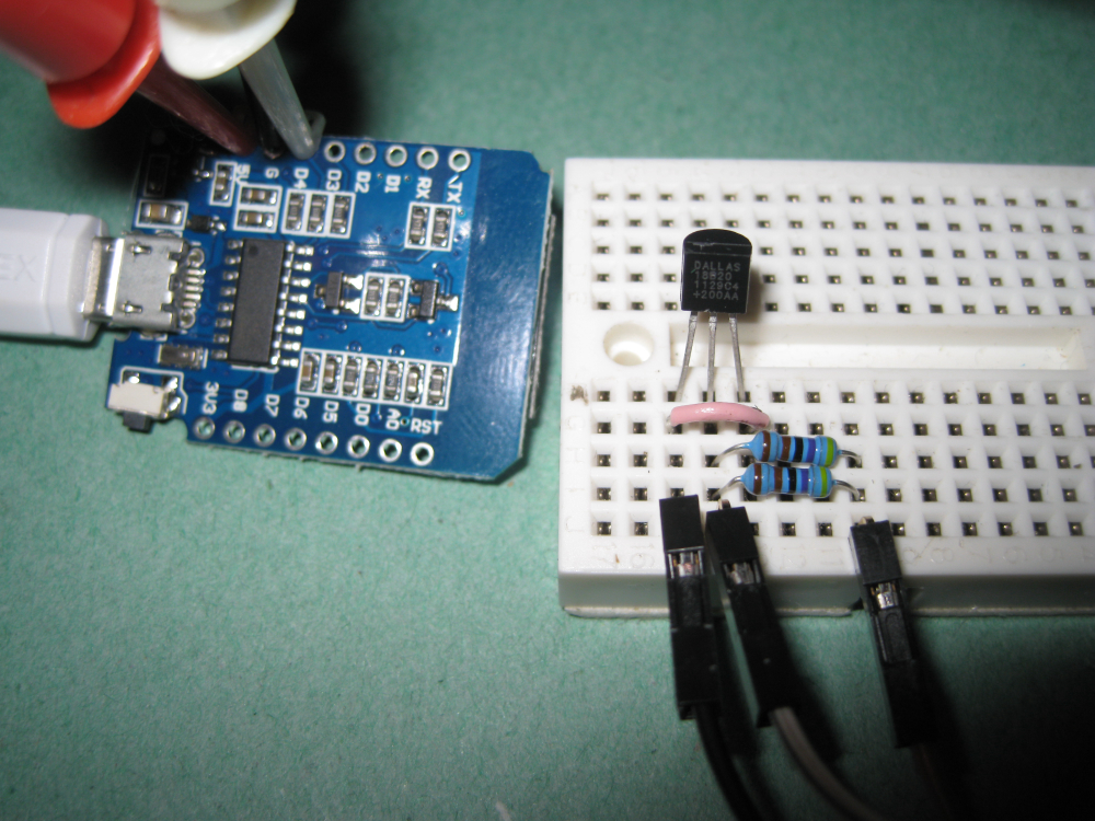
@sirzlimz I have just tried this circuit out myself on a D1 module and the using the library listed from milesburton it does not work on the ESP8266 in parasitic mode.
If you move the jumper over for powered mode it will work fine.Trying on an Arduino nano with the same device and breadboard it works fine in both modes.
So testing again and reading the data sheet on the DS18B20 and the section on "Powering the DS18B20" page 7 some insight can be obtained.
Anyway a quick fix is to put another 4.7K resistor in parallel with the first and the system should work with one sensor,
so two possible ways of connection are shown
Powered Mode with the Jumper to 5V, Recommended method, I always power my DS18B20's
This works with multiple devices, (I have just tried with 10 devices on the D1 [with multiple device sketch])
Parasitic Mode with two 4.7K resistors (this trick only works with one device on the bus)
-
@sirzlimz I have just tried this circuit out myself on a D1 module and the using the library listed from milesburton it does not work on the ESP8266 in parasitic mode.
If you move the jumper over for powered mode it will work fine.Trying on an Arduino nano with the same device and breadboard it works fine in both modes.
So testing again and reading the data sheet on the DS18B20 and the section on "Powering the DS18B20" page 7 some insight can be obtained.
Anyway a quick fix is to put another 4.7K resistor in parallel with the first and the system should work with one sensor,
so two possible ways of connection are shown
Powered Mode with the Jumper to 5V, Recommended method, I always power my DS18B20's
This works with multiple devices, (I have just tried with 10 devices on the D1 [with multiple device sketch])
Parasitic Mode with two 4.7K resistors (this trick only works with one device on the bus)
@hard-shovel Awesome, I'm excited to try this with my own setup when I get home. Thanks for explaining those nuances. I'm sure there will be many more stumbles as I get more into this stuff. There aren't really any "how to get started" guides for folks who aren't already programmers and electrical engineers (at least I haven't found any). I see a lot of copy/pasta in my future!
-
@sirzlimz I have just tried this circuit out myself on a D1 module and the using the library listed from milesburton it does not work on the ESP8266 in parasitic mode.
If you move the jumper over for powered mode it will work fine.Trying on an Arduino nano with the same device and breadboard it works fine in both modes.
So testing again and reading the data sheet on the DS18B20 and the section on "Powering the DS18B20" page 7 some insight can be obtained.
Anyway a quick fix is to put another 4.7K resistor in parallel with the first and the system should work with one sensor,
so two possible ways of connection are shown
Powered Mode with the Jumper to 5V, Recommended method, I always power my DS18B20's
This works with multiple devices, (I have just tried with 10 devices on the D1 [with multiple device sketch])
Parasitic Mode with two 4.7K resistors (this trick only works with one device on the bus)
@hard-shovel It worked! I used pin 4 on the D1 Mini and did direct power and i'm reading temps now! Thank you so much! One final question about the pinouts. Is there some kind of guide that you know of to determine which pins to use? i.e. how did you know how to use pin 4 on the D1 Mini but keep 2 specified in the sketch? Please ELI5.
-
@hard-shovel It worked! I used pin 4 on the D1 Mini and did direct power and i'm reading temps now! Thank you so much! One final question about the pinouts. Is there some kind of guide that you know of to determine which pins to use? i.e. how did you know how to use pin 4 on the D1 Mini but keep 2 specified in the sketch? Please ELI5.
@sirzlimz There are lots of pinout diagrams on the web like below.
For the the arduino use the GPIO number as the pin number
ie
GPIO5 --- marked D1 in Arduino IDE use 5
GPIO13-marked D7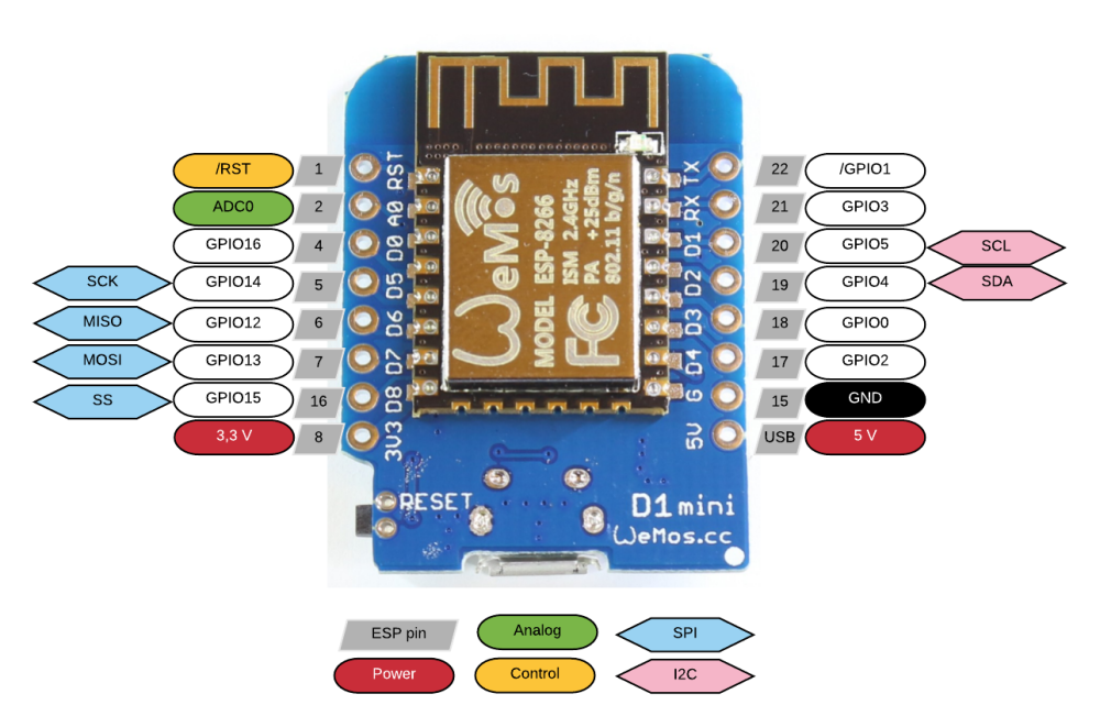
-
@sirzlimz I have just tried this circuit out myself on a D1 module and the using the library listed from milesburton it does not work on the ESP8266 in parasitic mode.
If you move the jumper over for powered mode it will work fine.Trying on an Arduino nano with the same device and breadboard it works fine in both modes.
So testing again and reading the data sheet on the DS18B20 and the section on "Powering the DS18B20" page 7 some insight can be obtained.
Anyway a quick fix is to put another 4.7K resistor in parallel with the first and the system should work with one sensor,
so two possible ways of connection are shown
Powered Mode with the Jumper to 5V, Recommended method, I always power my DS18B20's
This works with multiple devices, (I have just tried with 10 devices on the D1 [with multiple device sketch])
Parasitic Mode with two 4.7K resistors (this trick only works with one device on the bus)
@hard-shovel Parasitic power mode uses only two wires i.e. Data & GND, the sensor "parasitically" takes power from the Data line. In the second picture, VCC is connected as well so it might not be the parasitic power mode.
-
@hard-shovel Parasitic power mode uses only two wires i.e. Data & GND, the sensor "parasitically" takes power from the Data line. In the second picture, VCC is connected as well so it might not be the parasitic power mode.
@prakhar-birla Please explain how the DS18B20 will not be parasitic mode when it only has GND connected on pins 1 and 3 and data (with pull-up) on pin 2?
Hello! It looks like you're interested in this conversation, but you don't have an account yet.
Getting fed up of having to scroll through the same posts each visit? When you register for an account, you'll always come back to exactly where you were before, and choose to be notified of new replies (either via email, or push notification). You'll also be able to save bookmarks and upvote posts to show your appreciation to other community members.
With your input, this post could be even better 💗
Register Login