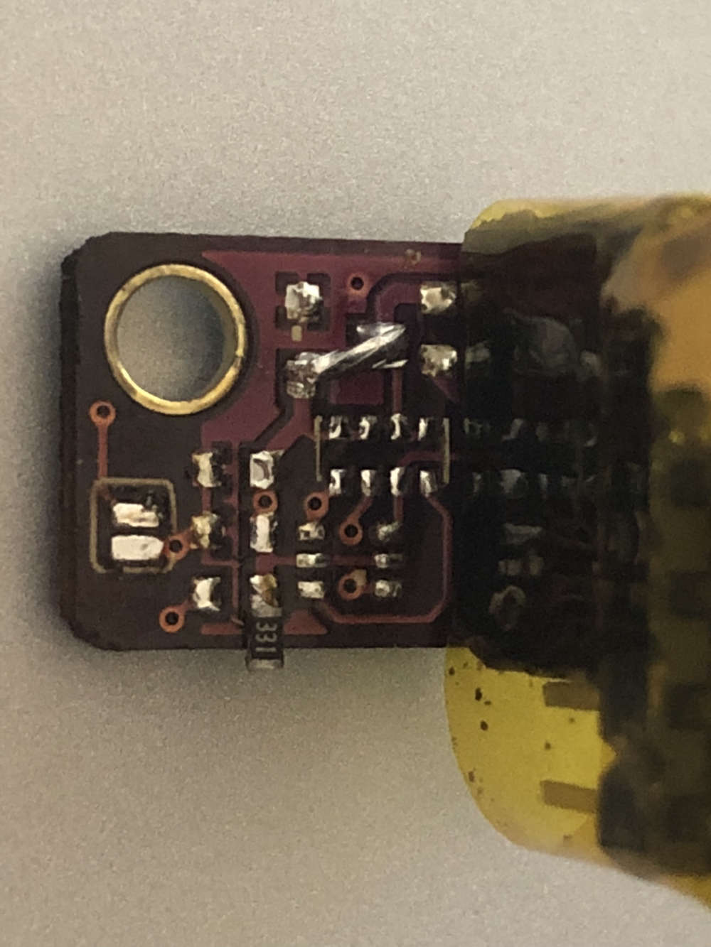
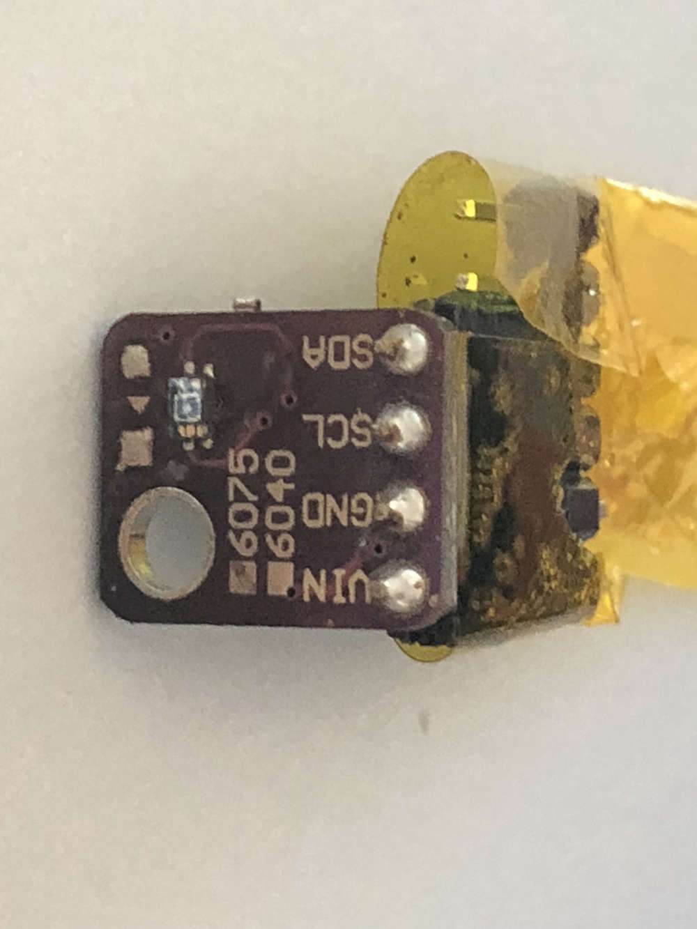
VEML6070 and VEML6075 UV sensors
-
Hi,
I am building a UV reporting node.
I need to present the following:- μW per cm²
- UV Index (0-11+)
What's the best pay to present it to GW and controller (Domoticz)?
- μW per cm² -> S_UV / V_UV
-UV Index -> S_LIGHT_LEVEL/V_LIGHT_LEVEL???
Thanks
Alex
-
for the moment, if i'm not wrong, i'm using S_UV/V_UV for UV index. and temporarily S_POWER/V_WATT for uW/cm².
Also note, depending on usecase, VEML6075 is better regarding its voltage range (i'm using both)
-
@scalz So you are using a temp one as well for uW/cm2...
VEML6075 is a more complex one. I think it can differentiate UV-a and UV-b or something. I ordered it a short while ago, but it would take some time before it arrives. Right now I have to think where to place it so that (1) the battery sensor is water tight if placed externally (2) direct UV exposure to the sensor (3) a transparent lid? Possible to 3d print? (4) externally or internally?
-
@alexsh1 for type of msg, yep..
hehe i have some custom boards with this one I'm using it because of voltage range, one less part, and "new". UVA/UVB is a nice bonus then.
For the enclosure, i'm still thinking the best options regarding environments i want to use them.
If printing for outdoor, i would recommend PETG, ABS (more tricky), or better but more expensive ASA.
-
@scalz The sensor has got a certain angle (55 degrees half sensitivity if I remember correctly) to provide the correct reading so the ideal place for it would be a roof? This would put an extra hurdle on enclosure design.
I suppose it has to be outside. I can seal atmega328p with electronic leaving only the battery box and the sensor. However, as I said before designing the box is very tricky.
-
http://www.vishay.com/docs/84310/designingveml6070.pdf
Interesting info on the sensor
-
Normal transparent glass can apparently block up to 75% of UV-B..
So one should look into what to use as a window over the chip area..
-
@tbowmo correct. This is why it has to be placed outside. And the sensor must be exposed as well. We need to build MySensors watertight IP67 enclosure now
-
But you can not expose the sensor to rain etc. So you still need to have some cover above the chip, and this should be UV transparent..
-
@tbowmo As I have just discovered there is a UV transparent plastic.
Maybe the enclosure can be 3D printed with such plastic?There is also a UV transparent glass.
-
The sensor has a peak
sensitivity at 355 nm.UV Spectrum:
UV-a -> 315-400nm
UV-b -> 280-315nm
UV-c -> 100-280nmUV-a goes through the glass and is a major one
UV-b account for only 3% of UV radiation
UV-c is absorbed by ozone layer
-
@alexsh1 so if i were you i would have bought a veml6075 when you ordered at some ic supplier! I'm joking.. or not
-
Anyone care to share a sketch that includes the VEML6075?
-
@korttoma I have not received VEML6075 yet so cannot help you
-
@korttoma what do you need exactly?? I can share some example, but there is nothing fancy for veml6075. On my side i'm using this lib for the moment https://github.com/schizobovine/VEML6075 , not digged much yet but it's working with MySensors of course. You simply need the same cooking in your sketch, as usual
-
Well, I'm looking to replace my Oregon Scientific UV Sensor UVN800 (that finally stopped reporting any values) by using a VEML6075 and a Sensebender Micro.
I can probably work out the code for the sketch myself but I'm not a fan of reinventing the wheel so if someone already created a sketch it would simply save me the time.
I would expect the sensor to report a UV Index value between 0 and 10 like the Oregon sensor did according to this -> https://www.epa.gov/sunsafety/uv-index-scale-1
The example in the Lib you mentioned @scalz seems to have the UV Index posibility
-
@korttoma this thread is about VEML6075
However, VEML6075 is more complex - it does report uv-a and uv-b. I do not think you'd get UVI from this sensor straight away, you'd need to do it in the sketch.I can share the sketch after I get the sensor, write a code and convert it into MySensors
-
@korttoma oki, i agree with you about reinventing the wheel, but for big job. I think it's always better to know how to use the lib, so that's not a waste imho
No time for the moment to check my bigger sketch and extract everything.
But in case you would like to try your new sensor, here a quick 5-10min conversion and mix of the lib example to mysensors uv. I wouldn't release it like this, not optimized, and untested version. But it's compiling, it should work
// Enable debug prints to serial monitor #define MY_DEBUG // Enable and select radio type attached #define MY_RADIO_NRF24 //#define MY_RADIO_RFM69 //#define MY_NODE_ID 10 #include <MySensors.h> #include <VEML6075.h> VEML6075 veml6075 = VEML6075(); bool sensorFound = false; #define CHILD_ID_UVI 0 #define CHILD_ID_UVA 0 #define CHILD_ID_UVB 0 uint32_t SLEEP_TIME = 30*1000; // Sleep time between reads (in milliseconds) MyMessage uviMsg(CHILD_ID_UVI, V_UV); MyMessage uvaMsg(CHILD_ID_UVA, V_UV); MyMessage uvbMsg(CHILD_ID_UVB, V_UV); void presentation() { // Send the sketch version information to the gateway and Controller sendSketchInfo("UV Sensor", "1.3"); // Register all sensors to gateway (they will be created as child devices) present(CHILD_ID_UVI, S_UV); present(CHILD_ID_UVA, S_UV); present(CHILD_ID_UVB, S_UV); } void setup() { if (!veml6075.begin()) { Serial.println(F("VEML6075 not found!")); } else sensorFound = true; } void loop() { if (sensorFound) { unsigned long lastSend =0; float uvi; float uva; float uvb; static float uviOld = -1; static float uvaOld = -1; static float uvbOld = -1; // Poll sensor veml6075.poll(); uva = veml6075.getUVA(); Serial.print(F("UVA = ")); Serial.println(uva, 2); uvb = veml6075.getUVB(); Serial.print(F("UVB = ")); Serial.println(uvb, 2); uvi = veml6075.getUVIndex(); Serial.print(F("UV Index = ")); Serial.println(uvi, 1); uint16_t devid = veml6075.getDevID(); Serial.print(F("Device ID = ")); Serial.println(devid, HEX); Serial.println(F("----------------")); if (uvi != uviOld) { send(uviMsg.set(uvi,2)); uviOld = uvi; } if (uva != uvaOld) { send(uvaMsg.set(uva,2)); uvaOld = uva; } if (uvb != uvbOld) { send(uvbMsg.set(uvb,2)); uvbOld = uvb; } } sleep(SLEEP_TIME); }
It simply read sensor, send messages, and sleep.
As you can see, it's possible to get the three values from the lib.
-
Thanks for the sketch @scalz , I made an attempt at it myself also. I was not avare that V_UV and S_UV could be used so I had V/S_LIGHT_LEVEL but I changed it now. Seems to compile just fine. Just need to get it tested.
SensebenderMicroWithUVIndex:
/** * The MySensors Arduino library handles the wireless radio link and protocol * between your home built sensors/actuators and HA controller of choice. * The sensors forms a self healing radio network with optional repeaters. Each * repeater and gateway builds a routing tables in EEPROM which keeps track of the * network topology allowing messages to be routed to nodes. * * Created by Henrik Ekblad <henrik.ekblad@mysensors.org> * Copyright (C) 2013-2015 Sensnology AB * Full contributor list: https://github.com/mysensors/Arduino/graphs/contributors * * Documentation: http://www.mysensors.org * Support Forum: http://forum.mysensors.org * * This program is free software; you can redistribute it and/or * modify it under the terms of the GNU General Public License * version 2 as published by the Free Software Foundation. * ******************************* * * REVISION HISTORY * Version 1.0 - Thomas Bowman Mørch * * DESCRIPTION * Default sensor sketch for Sensebender Micro module * Act as a temperature / humidity sensor by default. * * If A0 is held low while powering on, it will enter testmode, which verifies all on-board peripherals * * Battery voltage is as battery percentage (Internal message), and optionally as a sensor value (See defines below) * * * Version 1.3 - Thomas Bowman Mørch * Improved transmission logic, eliminating spurious transmissions (when temperatuere / humidity fluctuates 1 up and down between measurements) * Added OTA boot mode, need to hold A1 low while applying power. (uses slightly more power as it's waiting for bootloader messages) * * Version 1.4 - Thomas Bowman Mørch * * Corrected division in the code deciding whether to transmit or not, that resulted in generating an integer. Now it's generating floats as expected. * Simplified detection for OTA bootloader, now detecting if MY_OTA_FIRMWARE_FEATURE is defined. If this is defined sensebender automaticly waits 300mS after each transmission * Moved Battery status messages, so they are transmitted together with normal sensor updates (but only every 60th minute) * */ // Enable debug prints to serial monitor //#define MY_DEBUG // Define a static node address, remove if you want auto address assignment #define MY_NODE_ID 27 // Enable and select radio type attached #define MY_RADIO_NRF24 //#define MY_RADIO_RFM69 // Enable to support OTA for this node (needs DualOptiBoot boot-loader to fully work) //#define MY_OTA_FIRMWARE_FEATURE #include <SPI.h> #include <MySensors.h> #include <Wire.h> #include <SI7021.h> #ifndef MY_OTA_FIRMWARE_FEATURE #include "drivers/SPIFlash/SPIFlash.cpp" #endif #include <EEPROM.h> #include <sha204_lib_return_codes.h> #include <sha204_library.h> #include <RunningAverage.h> #include <VEML6075.h> //#include <avr/power.h> // Uncomment the line below, to transmit battery voltage as a normal sensor value //#define BATT_SENSOR 199 #define RELEASE "1.4" #define AVERAGES 2 // Child sensor ID's #define CHILD_ID_UVI 1 #define CHILD_ID_TEMP 2 #define CHILD_ID_HUM 3 // How many milli seconds between each measurement #define MEASURE_INTERVAL 60000 // How many milli seconds should we wait for OTA? #define OTA_WAIT_PERIOD 300 // FORCE_TRANSMIT_INTERVAL, this number of times of wakeup, the sensor is forced to report all values to the controller #define FORCE_TRANSMIT_INTERVAL 30 // When MEASURE_INTERVAL is 60000 and FORCE_TRANSMIT_INTERVAL is 30, we force a transmission every 30 minutes. // Between the forced transmissions a tranmission will only occur if the measured value differs from the previous measurement // HUMI_TRANSMIT_THRESHOLD tells how much the humidity should have changed since last time it was transmitted. Likewise with // TEMP_TRANSMIT_THRESHOLD for temperature threshold. #define HUMI_TRANSMIT_THRESHOLD 0.5 #define TEMP_TRANSMIT_THRESHOLD 0.5 #define UVI_TRANSMIT_THRESHOLD 0.1 // Pin definitions #define TEST_PIN A0 #define LED_PIN A2 #define ATSHA204_PIN 17 // A3 VEML6075 veml6075 = VEML6075(); const int sha204Pin = ATSHA204_PIN; atsha204Class sha204(sha204Pin); SI7021 humiditySensor; SPIFlash flash(8, 0x1F65); // Sensor messages MyMessage msgHum(CHILD_ID_HUM, V_HUM); MyMessage msgTemp(CHILD_ID_TEMP, V_TEMP); MyMessage msgUVI(CHILD_ID_UVI, V_UV); #ifdef BATT_SENSOR MyMessage msgBatt(BATT_SENSOR, V_VOLTAGE); #endif // Global settings int measureCount = 0; int sendBattery = 0; boolean isMetric = true; boolean highfreq = true; boolean transmission_occured = false; // Storage of old measurements float lastTemperature = -100; int lastHumidity = -100; long lastBattery = -100; int lastUVI = -100; RunningAverage raHum(AVERAGES); /**************************************************** * * Setup code * ****************************************************/ void setup() { pinMode(LED_PIN, OUTPUT); digitalWrite(LED_PIN, LOW); //Serial.begin(115200); //Serial.print(F("Sensebender Micro FW ")); //Serial.print(RELEASE); //Serial.flush(); // First check if we should boot into test mode pinMode(TEST_PIN,INPUT); digitalWrite(TEST_PIN, HIGH); // Enable pullup if (!digitalRead(TEST_PIN)) testMode(); // Make sure that ATSHA204 is not floating pinMode(ATSHA204_PIN, INPUT); digitalWrite(ATSHA204_PIN, HIGH); digitalWrite(TEST_PIN,LOW); digitalWrite(LED_PIN, HIGH); humiditySensor.begin(); veml6075.begin(); digitalWrite(LED_PIN, LOW); //Serial.flush(); //Serial.println(F(" - Online!")); isMetric = getControllerConfig().isMetric; //Serial.print(F("isMetric: ")); Serial.println(isMetric); raHum.clear(); sendTempHumidityMeasurements(false); sendBattLevel(false); #ifdef MY_OTA_FIRMWARE_FEATURE //Serial.println("OTA FW update enabled"); #endif } void presentation() { sendSketchInfo("Sensebender Micro", RELEASE); present(CHILD_ID_UVI,S_UV); present(CHILD_ID_TEMP,S_TEMP); present(CHILD_ID_HUM,S_HUM); #ifdef BATT_SENSOR present(BATT_SENSOR, S_POWER); #endif } /*********************************************** * * Main loop function * ***********************************************/ void loop() { measureCount ++; sendBattery ++; bool forceTransmit = false; transmission_occured = false; #ifndef MY_OTA_FIRMWARE_FEATURE if ((measureCount == 5) && highfreq) { clock_prescale_set(clock_div_8); // Switch to 1Mhz for the reminder of the sketch, save power. highfreq = false; } #endif if (measureCount > FORCE_TRANSMIT_INTERVAL) { // force a transmission forceTransmit = true; measureCount = 0; } sendTempHumidityMeasurements(forceTransmit); /* if (sendBattery > 60) { sendBattLevel(forceTransmit); // Not needed to send battery info that often sendBattery = 0; }*/ #ifdef MY_OTA_FIRMWARE_FEATURE if (transmission_occured) { wait(OTA_WAIT_PERIOD); } #endif sleep(MEASURE_INTERVAL); } /********************************************* * * Sends temperature and humidity from Si7021 sensor * * Parameters * - force : Forces transmission of a value (even if it's the same as previous measurement) * *********************************************/ void sendTempHumidityMeasurements(bool force) { bool tx = force; si7021_env data = humiditySensor.getHumidityAndTemperature(); veml6075.poll(); float UVA = veml6075.getUVA(); //Serial.print(F("UVA = ")); //Serial.println(UVA, 2); float UVB = veml6075.getUVB(); //Serial.print(F("UVB = ")); //Serial.println(UVB, 2); float UVI = veml6075.getUVIndex(); //Serial.print(F("UV Index = ")); //Serial.println(UVI, 1); raHum.addValue(data.humidityPercent); float diffTemp = abs(lastTemperature - (isMetric ? data.celsiusHundredths : data.fahrenheitHundredths)/100.0); float diffHum = abs(lastHumidity - raHum.getAverage()); float diffUVI = abs(lastUVI - UVI); //Serial.print(F("TempDiff :"));Serial.println(diffTemp); //Serial.print(F("HumDiff :"));Serial.println(diffHum); //Serial.print(F("UVIDiff :"));Serial.println(diffUVI); if (isnan(diffHum)) tx = true; if (diffTemp > TEMP_TRANSMIT_THRESHOLD) tx = true; if (diffHum > HUMI_TRANSMIT_THRESHOLD) tx = true; if (diffUVI > UVI_TRANSMIT_THRESHOLD) tx = true; if (tx) { measureCount = 0; float temperature = (isMetric ? data.celsiusHundredths : data.fahrenheitHundredths) / 100.0; int humidity = data.humidityPercent; //Serial.print("T: ");Serial.println(temperature); //Serial.print("H: ");Serial.println(humidity); send(msgTemp.set(temperature,1)); send(msgHum.set(humidity)); send(msgUVI.set(UVI,2)); lastTemperature = temperature; lastHumidity = humidity; lastUVI = UVI; transmission_occured = true; if (sendBattery > 60) { sendBattLevel(true); // Not needed to send battery info that often sendBattery = 0; } } } /******************************************** * * Sends battery information (battery percentage) * * Parameters * - force : Forces transmission of a value * *******************************************/ void sendBattLevel(bool force) { if (force) lastBattery = -1; long vcc = readVcc(); if (vcc != lastBattery) { lastBattery = vcc; #ifdef BATT_SENSOR float send_voltage = float(vcc)/1000.0f; send(msgBatt.set(send_voltage,3)); #endif // Calculate percentage vcc = vcc - 1900; // subtract 1.9V from vcc, as this is the lowest voltage we will operate at long percent = vcc / 14.0; sendBatteryLevel(percent); transmission_occured = true; } } /******************************************* * * Internal battery ADC measuring * *******************************************/ long readVcc() { // Read 1.1V reference against AVcc // set the reference to Vcc and the measurement to the internal 1.1V reference #if defined(__AVR_ATmega32U4__) || defined(__AVR_ATmega1280__) || defined(__AVR_ATmega2560__) ADMUX = _BV(REFS0) | _BV(MUX4) | _BV(MUX3) | _BV(MUX2) | _BV(MUX1); #elif defined (__AVR_ATtiny24__) || defined(__AVR_ATtiny44__) || defined(__AVR_ATtiny84__) ADMUX = _BV(MUX5) | _BV(MUX0); #elif defined (__AVR_ATtiny25__) || defined(__AVR_ATtiny45__) || defined(__AVR_ATtiny85__) ADcdMUX = _BV(MUX3) | _BV(MUX2); #else ADMUX = _BV(REFS0) | _BV(MUX3) | _BV(MUX2) | _BV(MUX1); #endif delay(2); // Wait for Vref to settle ADCSRA |= _BV(ADSC); // Start conversion while (bit_is_set(ADCSRA,ADSC)); // measuring uint8_t low = ADCL; // must read ADCL first - it then locks ADCH uint8_t high = ADCH; // unlocks both long result = (high<<8) | low; result = 1125300L / result; // Calculate Vcc (in mV); 1125300 = 1.1*1023*1000 return result; // Vcc in millivolts } /**************************************************** * * Verify all peripherals, and signal via the LED if any problems. * ****************************************************/ void testMode() { uint8_t rx_buffer[SHA204_RSP_SIZE_MAX]; uint8_t ret_code; byte tests = 0; digitalWrite(LED_PIN, HIGH); // Turn on LED. //Serial.println(F(" - TestMode")); //Serial.println(F("Testing peripherals!")); //Serial.flush(); //Serial.print(F("-> SI7021 : ")); //Serial.flush(); if (humiditySensor.begin()) { //Serial.println(F("ok!")); tests ++; } else { //Serial.println(F("failed!")); } //Serial.flush(); //Serial.print(F("-> Flash : ")); //Serial.flush(); if (flash.initialize()) { //Serial.println(F("ok!")); tests ++; } else { //Serial.println(F("failed!")); } //Serial.flush(); //Serial.print(F("-> SHA204 : ")); ret_code = sha204.sha204c_wakeup(rx_buffer); //Serial.flush(); if (ret_code != SHA204_SUCCESS) { //Serial.print(F("Failed to wake device. Response: ")); Serial.println(ret_code, HEX); } //Serial.flush(); if (ret_code == SHA204_SUCCESS) { ret_code = sha204.getSerialNumber(rx_buffer); if (ret_code != SHA204_SUCCESS) { //Serial.print(F("Failed to obtain device serial number. Response: ")); Serial.println(ret_code, HEX); } else { //Serial.print(F("Ok (serial : ")); for (int i=0; i<9; i++) { if (rx_buffer[i] < 0x10) { //Serial.print('0'); // Because Serial.print does not 0-pad HEX } //Serial.print(rx_buffer[i], HEX); } //Serial.println(")"); tests ++; } } //Serial.flush(); //Serial.println(F("Test finished")); if (tests == 3) { //Serial.println(F("Selftest ok!")); while (1) // Blink OK pattern! { digitalWrite(LED_PIN, HIGH); delay(200); digitalWrite(LED_PIN, LOW); delay(200); } } else { //Serial.println(F("----> Selftest failed!")); while (1) // Blink FAILED pattern! Rappidly blinking.. { } } }
-
This is the VEML6070 UV Index graph. The last day, I placed the sensor outside rather than behind my window. There is a huge difference :
-
I finally received VEML6075 and comparing it with VEML6070 side y side
_____UVI__UVA__UVB
6070 0.96075 1.2 1036.53 1005.31
Not sure why there is a difference in UVI
-
Did anyone measure the current consumption of these VEML chips?
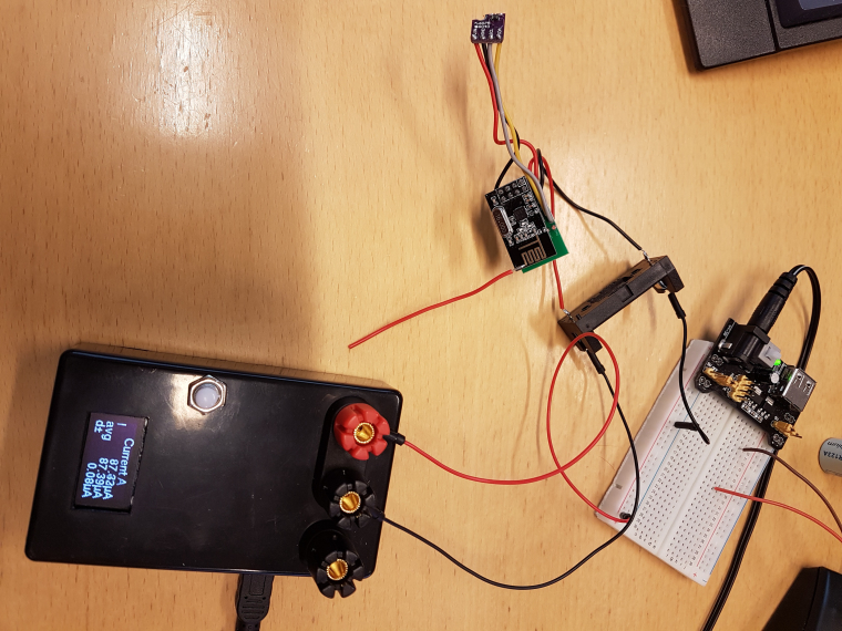
I just compared a Sensebender Micro with the VEML6075 to a standalone Sensebender Micro and the standalone one measured 28uA and the one with the VEML6075 measured 740uA.I just checked the VEML6075 documentation and typical consumption is 480uA but it should also be possible to shut it down and then it should only draw 800nA.
I need to check the Lib if there is some function to shut it down and wake it up. Or else I will try to change the setup so I can power the VEML6075 from an output pin so I can turn it completely off.
-
@korttoma
if i remember, sleep is not implemented in the veml6075 lib above. I added a sleep function and set the corresponding CONF register. not a big thing
-
@scalz please share your sleep function implementation it is quite a "big thing" for a non programmer.
-
@korttoma you can try this, and you'll see it's not a big thing
in your .h, in the public section, add this:
void sleep(bool mode);
then in the .cpp, add this:
void VEML6075::sleep(bool mode) { if (mode) this->config |= 1; // Go to sleep else this->config &= 254; // Wake up this->write16(VEML6075_REG_CONF, this->config); }
In your sketch, just do this:
veml6075.sleep(true); // power down veml6075
Note: i added this because i noticed it wasn't implemented, but i've not checked the power consumption yet. So if you can tell me if it's ok, please!
Enjoy
-
@scalz thanks for the sleep function! The current consumption is now down to 85uA but the problem is that onece it sleeps I cant get it to wake up.
Tried with:
veml6075.sleep(false);
Tried allso adding a 500ms sleep after the wakeup to give it time to setle.
But do I need to do something more?
-
@korttoma sorry for the copy/paste mistake you can try again, i've updated above. maybe someday i'll measure power consuption of a sensebender, weird that you get 28uA for the standalone..
-
@scalz seems to be working now don´t take my current consumtion figures to sareously since Im using the Micro (nano) ampere meter and I realy have nothing good to calibrate it against.
-
I have a strange problem. VEML6070 is showing UV Index 6, which is more or less in line with other online sources. VEML6075 is showing UV index 10.5, which is wrong. I'll double check the sketch once more but cannot understand where this error comes from
-
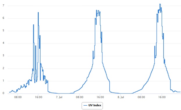
I mounted the Sensebender Micro VEML6075 inside my old broken UVN800 and set it in the roof. Here are graphs of the values I received the last 3 days. Unfortunately I do not have anything to compare with but the values seem reasonable.
-
@scalz FYG, I am using VEML6075 without sleep and it works now for nearly a year on 2xAA. I am still puzzled though by Index difference 6070 and 6075
-
Yeah, my 6075 device is also still working fine on the 2xAA batteries I put in it a year ago.
-
OK, I think found what the issue is. VEML 6070 is not providing accurate UV Index. Adafruit is stating the following:
Note that this is not UV index, its just UV light intensity!
This is how it can be converted into sort of UV Index according to the datasheet:
RISK_LEVEL convert_to_risk_level(WORD uvs_step) { WORD risk_level_mapping_table[4] = {2241, 4482, 5976, 8217}; } WORD read_uvs_step(void) { BYTE lsb, msb; WORD data; VEML6070_read_byte(VEML6070_ADDR_DATA_MSB, &msb); VEML6070_read_byte(VEML6070_ADDR_DATA_LSB, &lsb); data = ((WORD)msb << 8) | (WORD)lsb; return data; } LEVEL* UV Index ===== ======== LOW 0-2 MODERATE 3-5 HIGH 6-7 VERY HIGH 8-10 EXTREME >=11
-
@korttoma @scalz FYG I got a new DMM from Dave Jones 121GW and decided to measure a sleep current for VEML6075 and to my surprise:
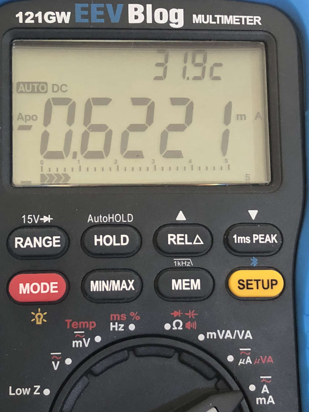
Quickly reading the datasheet I discovered my mistake:
- current supply - 480uA
- shutdown current - 800nA
Therefore, the sensor has to be put to sleep properly.
One can modify the existing lib:uint8_t VEML6075::Shutdown() { //Places device in shutdown low power mode Config = ReadByte(CONF_CMD, 0); //Update global config value return WriteConfig(Config | 0x01); //Set shutdown bit } uint8_t VEML6075::PowerOn() { //Turns device on from shutdown mode Config = ReadByte(CONF_CMD, 0); //Update global config value return WriteConfig(Config & 0xFE); //Clear shutdown bit } Make sure you define #define CONF_CMD 0x00
PS Now I understand why I did not change batteries - they are rechargeable. Charing and putting them back made me think that batteries lasted for a long time.
-
I have now three sensor from Vishay - VEML6040, VEML6070 and VEML6075
I can confirm all three sensors must be property put down to sleep with battery nodes or you would have the following sleeping currents on nodes with typical mysensors setup and standalone sleeping current of 4uA:VEML6040 - 240uA
VEML6070 - 94uA
VEML6075 - 622uAUnfortunately, most libraries do not care for properly sleeping/waking up sensors and therefore, one has to do a little tinkering with software to make it work. I am actually thinking about re-writing some libs completely.
-
Battery issues is one thing, SparkFun's VEML6075 library can't handle direct daylight even (compensated UV readings go negative).
-
@avamander That's impossible - it is designed to handle the direct sunlight. Mine is showing UV Index = 9. Negative UV reading is a software issue - looks like Sparkfun did not write a good lib for it. Did you try a different lib?
-
Did you try a different lib?
Haven't bothered, I'm just logging the raw values and then compensating with software.
-
@avamander It definitely works.
My problem for now was just the battery consumption. I have one of these:
The problem is that it is dodgy - the sleep consumption never goes below 50uA at 3.2V. According to the datasheet it should be 800nA while sleeping at 1.8V and 25C. Can anyone measure a shutdown current for VEML6085 please?
-
@alexsh1 I have the same board, there seems to be a regulator and a few other components on the board, if you remove those, how's the power consumption then?
-
@avamander I have removed every component bit by bit. Originally the consumption was 56uA and now it is 50uA with the only sensor left on the board
-
@alexsh1 There's an I^2C address selection jumper on the board, maybe that draws current?
-
@avamander desoldered
-
@alexsh1 Just desolder the sensor itself from the board if you're that far already? I wouldn't be surprised if aliexpress sellers sell counterfeit chips that are s****ier, I'm already seeing that with nRF24L01+'s
-
@avamander I tried to resolder it to the board - no luck.
It is very small. Very hard to solder any wires to it
-
Ok, I did manage to solder the bare sonsor.
Consumption is still 50uA.Can anyone please let me know your VELM6075 break board consumption?????
-
@alexsh1 I'd do it but I'm waiting for my replacement multimeter to arrive, sorry.
-
@avamander That's ok. Just post values here - other may benefit on this as well.
I still have no idea why the sensor is taking so much current
-
An old thread, tried the github ino for the VEML6075, is not working ok. UVA and UVB sometimes wrong negative figures. I am going to try the sparkfun library, is from 2018. Let you now if I get beter results.
-
This post is deleted!
-
/*
Original by scalz@mysensors: https://forum.mysensors.org/topic/6952/veml6070-and-veml6075-uv-sensors/25#
Needs a modified VEML6075-lib: https://github.com/rejoe2/VEML6075
rewritten by Tonbor using sparkfun libary
/
// Enable debug prints to serial monitor
#define MY_DEBUG
// Enable and select radio type attached
#define MY_RADIO_NRF24
//#define MY_RADIO_RFM69
//#define MY_NODE_ID 10
#include <MySensors.h>
#include <SparkFun_VEML6075_Arduino_Library.h>
VEML6075 uv;
//VEML6075 veml6075 = VEML6075();
bool sensorFound = false;
#define CHILD_ID_UVI 1
#define CHILD_ID_UVA 2
#define CHILD_ID_UVB 3
uint32_t SLEEP_TIME = 301000; // Sleep time between reads (in milliseconds)
MyMessage uviMsg(CHILD_ID_UVI, V_UV);
MyMessage uvaMsg(CHILD_ID_UVA, V_UV);
MyMessage uvbMsg(CHILD_ID_UVB, V_UV);
void presentation()
{
// Send the sketch version information to the gateway and Controller
sendSketchInfo("UV Sensor", "1.4T");
// Register all sensors to gateway (they will be created as child devices)
present(CHILD_ID_UVI, S_UV);
present(CHILD_ID_UVA, S_UV);
present(CHILD_ID_UVB, S_UV);
}
void setup()
{
if (!uv.begin()) {
Serial.println(F("VEML6075 not found!"));
} else
sensorFound = true;
//#ifdef MY_DEBUG
// uint16_t devid = veml6075.getDevID();
// Serial.print(F("Device ID = "));
// Serial.println(devid, HEX);
// Serial.println(F("----------------"));
//#endif
}
void loop()
{
if (sensorFound) {
unsigned long lastSend =0;
float uvi;
float uva;
float uvb;
static float uviOld = -1;
static float uvaOld = -1;
static float uvbOld = -1;
//veml6075.sleep(false); // power up veml6075 == begin()
//sleep(500);
// Poll sensor
//veml6075.poll();
uv.powerOn();
delay(250);
uva = uv.a();
uvb = uv.b();
uvi = uv.index();
#ifdef MY_DEBUG
Serial.print(F("UVA = "));
Serial.println(uva, 2);
Serial.print(F("UVB = "));
Serial.println(uvb, 2);
Serial.print(F("UV Index = "));
Serial.println(uvi, 1);
#endif
if (uvi != uviOld) {
send(uviMsg.set(uvi,2));
uviOld = uvi;
}
if (uva != uvaOld) {
send(uvaMsg.set(uva,2));
uvaOld = uva;
}
if (uvb != uvbOld) {
send(uvbMsg.set(uvb,2));
uvbOld = uvb;
}
}
uv.shutdown(); ; // power down veml6075
sleep(SLEEP_TIME);
}
-
This ino is working for me, it has the sleep function to save batteries. The Adafruit en the github/mysensors-> https://github.com/schizobovine/VEML6075 lib gives far to high index with my sensor. Only uv a and uv b declaration is not correct. Uv expect a index 0 till 11, domoticz controller passes a lower figure when it receives a number above 11.