MY_SOFTSPI on Sensebender-Micro Derivate


-
Hi,
The Background
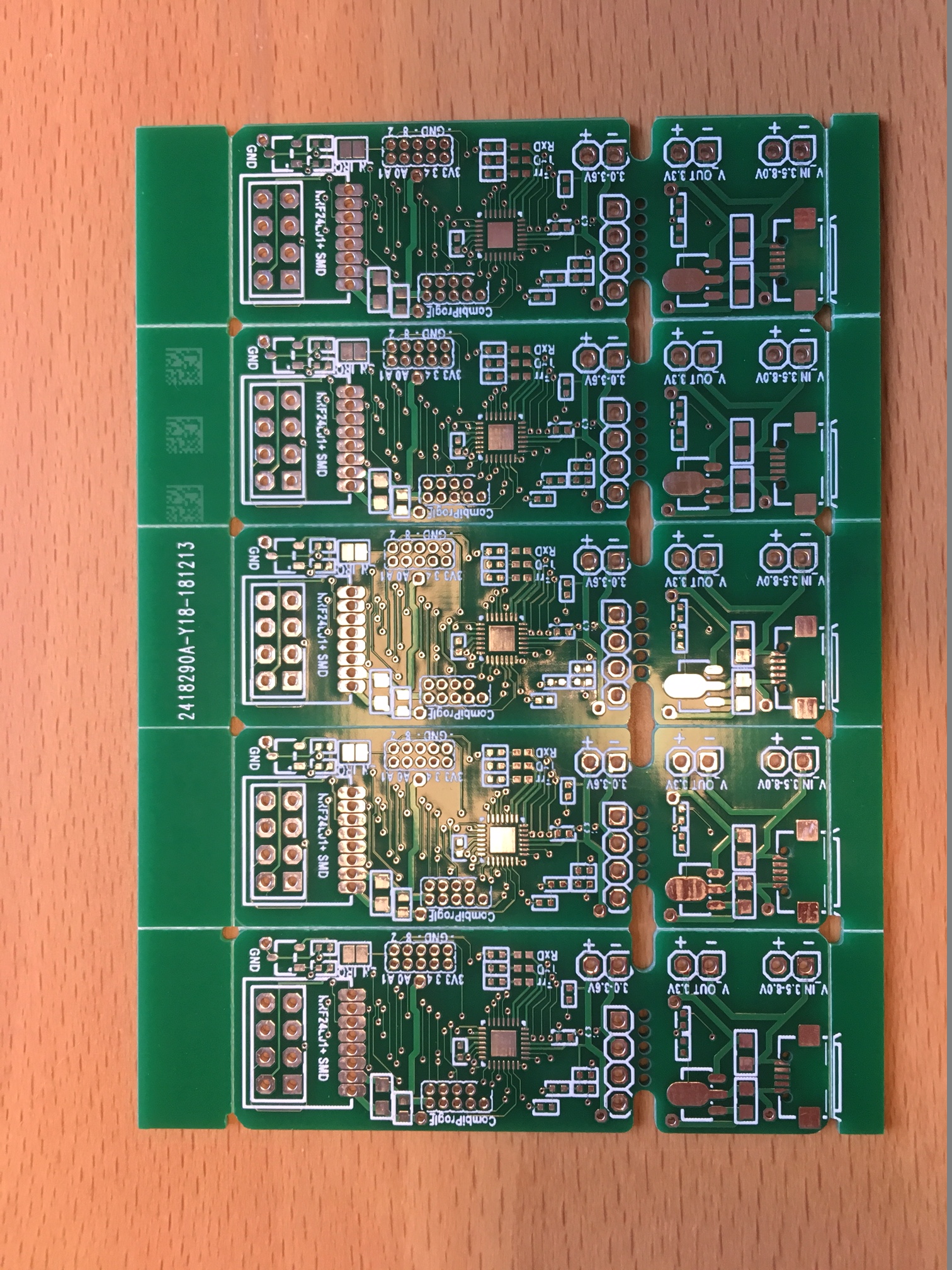
I have a simple question regarding the MY_SOFTSPI functionality. I designed my own pcb for a Sensebender Micro derviate that is utilizing a ATMEGA328-MMH chip (the 4x4mm SMD version) and mainly 0402 SMD parts.Here some impressions:

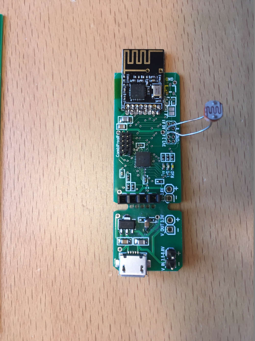
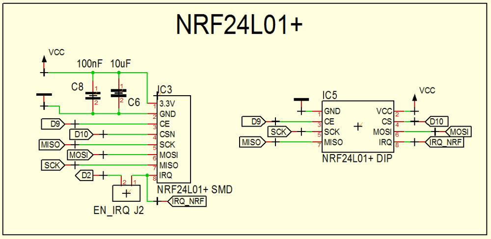
The PCBs are equipped with both footprints for the DIP and the SMD version of the NRF24 modules. However, I made a stupic mistake when wiring the SMD footprint and swapped the MISO and SCK connections.
Here the thing (grrrrrr):
The Issue
I hoped to resolve this stupid mistake with these lines of code to swap the connections again:#define MY_SOFTSPI #define MY_SOFT_SPI_SCK_PIN 12 #define MY_SOFT_SPI_MISO_PIN 13 #define MY_SOFT_SPI_MOSI_PIN 11... but it doesn't work out.
The serial outputs is:
 __  __       ____
|  \/  |_   _/ ___|  ___ _ __  ___  ___  _ __ ___
| |\/| | | | \___ \ / _ \ `_ \/ __|/ _ \| `__/ __|
| |  | | |_| |___| |  __/ | | \__ \  _  | |  \__ \
|_|  |_|\__, |____/ \___|_| |_|___/\___/|_|  |___/
        |___/                      2.3.0

16 MCO:BGN:INIT NODE,CP=RNNNA---,VER=2.3.0
26 TSM:INIT
28 TSF:WUR:MS=0
34 !TSM:INIT:TSP FAIL
36 TSM:FAIL:CNT=1
38 TSM:FAIL:DIS
40 TSF:TDI:TSL
10045 TSM:FAIL:RE-INIT
10047 TSM:INIT
10053 !TSM:INIT:TSP FAIL
10057 TSM:FAIL:CNT=2
10059 TSM:FAIL:DIS
10061 TSF:TDI:TSL
If I unsolder the NRF24-SMD version, plug the DIP version in (edit: and modify the code so that the hardware-SPI is used again), it is working instantly.
So my guess is that it is not possible to use the native SPI pins as softSPI pins. Is this correct?
Regards from cold Germany,
Marco -
Hello,
never tried this way, but I don't see why it wouldn't work. it's software spi..
Maybe show us your sketch, and add this define, so you can check in logs which pins are really used by the radio driver#define MY_DEBUG_VERBOSE_RF24imho, hardware spi is always preferable, so I would have fixed it the other way, like cutting traces and soldering thin wires to get it working again
-
Hi @scalz ,
thanks for the rapid reaction. Sure. Let's try this.
Here is my code:/* --- Bathroom Environment Data Logging Node --- */ // +-+-+-+-+-+-+-+-+ DECLARATION +-+-+-+-+-+-+-+-+ // --- MYSENSORS DEFINITIONS --- // sketch #define SKETCH_NAME "EnvBad" #define SKETCH_VERSION "1.1" // debug prints #define MY_BAUD_RATE (115200) #define MY_DEBUG #define MY_DEBUG_VERBOSE_RF24 // soft SPI settings #define MY_SOFTSPI #define MY_SOFT_SPI_SCK_PIN 12 // (usually at pin 13) #define MY_SOFT_SPI_MISO_PIN 13 //(usually at pin 12) #define MY_SOFT_SPI_MOSI_PIN 11 // NRF24 #define MY_RADIO_NRF24 #define MY_RF24_PA_LEVEL (RF24_PA_HIGH) #define MY_RF24_CE_PIN 9 #define MY_RF24_CS_PIN 10 #define MY_RF24_IRQ_PIN 2 // need to be enabled using the solder jumper at the top side of the PCB // LEDs #define MY_DEFAULT_TX_LED_PIN 6 #define MY_DEFAULT_RX_LED_PIN 5 #define MY_DEFAULT_ERR_LED_PIN 7 #define MY_WITH_LEDS_BLINKING_INVERSE // node ID #define MY_NODE_ID (100) // child IDs #define CHILD_ID_TEMPERATURE (0) #define CHILD_ID_HUMIDITY (1) #define CHILD_ID_LIGHT (2) // --- CONSTANTS --- // pin definitions const uint8_t phResistorEnPin = 4; const uint8_t PHOTO_RESISTOR_PIN = A0 ; // Timing constants const uint32_t ENV_VARS_CHECK_PERIOD_MS = 60UL*1000UL; const uint32_t LIGHT_CHECK_PERIOD_MS = 1UL*1000UL; // --- LIBRARIES --- #include <MySensors.h> #include <SHT3x.h> // temp and humidity sensor // --- Objects SHT3x Sensor; // ------------------------------------------------------------------------ // S E T U P // ------------------------------------------------------------------------ void setup() { Serial.println(F("-- " SKETCH_NAME " " SKETCH_VERSION)); Sensor.Begin(); } // ------------------------------------------------------------------------ // L O O P // ------------------------------------------------------------------------ void loop() { float tSHT; float hSHT; static uint8_t lightLev = 0, lightLevPrev = 200; static uint32_t t1 = millis(), t2 = 0; readPhRest(&lightLev); if ( abs(lightLevPrev - lightLev) >= 2 ) { lightLevPrev = lightLev; send( MyMessage(CHILD_ID_LIGHT, V_LIGHT_LEVEL).set(lightLev) ); } if ( t2 - t1 >= ENV_VARS_CHECK_PERIOD_MS ) { readSHT3x(&tSHT, &hSHT); send( MyMessage(CHILD_ID_TEMPERATURE, V_TEMP).set(double(tSHT), 2 /*#decimals*/) ); send( MyMessage(CHILD_ID_HUMIDITY, V_HUM).set(double(hSHT), 2 /*#decimals*/) ); t1 = t2; } wait(LIGHT_CHECK_PERIOD_MS); t2 = millis(); } // ------------------------------------------------------------------------ // SUB - ROUTINES // ------------------------------------------------------------------------ // ----------------------- presentation -------------------------- void presentation() { Serial.println(F("-- Init MySensors")); sendSketchInfo(SKETCH_NAME, SKETCH_VERSION); Serial.print(F("NodeID: ")); Serial.println(getNodeId()); present(CHILD_ID_TEMPERATURE, S_TEMP, "Bad_Temp"); present(CHILD_ID_HUMIDITY, S_HUM, "Bad_LuFeu"); present(CHILD_ID_LIGHT, S_LIGHT_LEVEL, "Bad_Hell"); } // ----------------------- readSHT3x -------------------------- void readSHT3x(float *_tSHT, float *_hSHT){ Sensor.UpdateData(); *_tSHT = Sensor.GetTemperature(); *_hSHT = Sensor.GetRelHumidity(); Serial.print("Temperature: "); Serial.print(*_tSHT); Serial.write("\xC2\xB0"); //The Degree symbol Serial.println("C"); Serial.print("Humidity: "); Serial.print(*_hSHT); Serial.println("%"); } // ----------------------- readPhRest -------------------------- void readPhRest(uint8_t *_lLevel) { pinMode(phResistorEnPin,OUTPUT); digitalWrite(phResistorEnPin,LOW); *_lLevel = 100 - (uint8_t) ( ( (float)analogRead(PHOTO_RESISTOR_PIN) /10.24 ) + 0.5 ) ; pinMode(phResistorEnPin,INPUT); Serial.print ("PhotoResistor: "); Serial.print (*_lLevel); Serial.println(); }and here my debug print:
 __  __       ____
|  \/  |_   _/ ___|  ___ _ __  ___  ___  _ __ ___
| |\/| | | | \___ \ / _ \ `_ \/ __|/ _ \| `__/ __|
| |  | | |_| |___| |  __/ | | \__ \  _  | |  \__ \
|_|  |_|\__, |____/ \___|_| |_|___/\___/|_|  |___/
        |___/                      2.3.0

16 MCO:BGN:INIT NODE,CP=RNNNA---,VER=2.3.0
26 TSM:INIT
28 TSF:WUR:MS=0
30 RF24:INIT
30 RF24:INIT:PIN,CE=9,CS=10
34 RF24:WBR:REG=0,VAL=14
43 RF24:WBR:REG=3,VAL=3
45 RF24:WBR:REG=4,VAL=95
47 RF24:WBR:REG=5,VAL=76
49 RF24:WBR:REG=6,VAL=37
53 RF24:WBR:REG=16,VAL=115
55 RF24:WBR:REG=29,VAL=4
57 RF24:RBR:REG=6,VAL=0
61 !RF24:INIT:SANCHK FAIL
63 !TSM:INIT:TSP FAIL
65 TSM:FAIL:CNT=1
67 TSM:FAIL:DIS
69 TSF:TDI:TSL
71 RF24:SLP
71 RF24:WBR:REG=0,VAL=12
10074 TSM:FAIL:RE-INIT
10076 TSM:INIT
10078 RF24:INIT
10080 RF24:INIT:PIN,CE=9,CS=10
10082 RF24:WBR:REG=0,VAL=14
10090 RF24:WBR:REG=3,VAL=3
10092 RF24:WBR:REG=4,VAL=95
10096 RF24:WBR:REG=5,VAL=76
10098 RF24:WBR:REG=6,VAL=37
10102 RF24:WBR:REG=16,VAL=115
10104 RF24:WBR:REG=29,VAL=4
10108 RF24:RBR:REG=6,VAL=0
10110 !RF24:INIT:SANCHK FAIL
10115 !TSM:INIT:TSP FAIL
10117 TSM:FAIL:CNT=2
10119 TSM:FAIL:DIS
10121 TSF:TDI:TSL
10123 RF24:SLP
10125 RF24:WBR:REG=0,VAL=12
Moreover, I tried to re-programm an otherwise well-performing node (one with a DIP NRF24) by adding these lines to the program:
#define   MY_SOFTSPI
#define   MY_SOFT_SPI_SCK_PIN     13
#define   MY_SOFT_SPI_MISO_PIN    12
#define   MY_SOFT_SPI_MOSI_PIN    11
... and i got identical errors. So it really might be a limit of the softSPI to not use the hardware SPI pins.
And considering the hint with the manual rewiring: Well, yes, I would consider this for one board but I want to deploy between 15 and 20 of those boards in our flat for varios types of sensors. I guess if software can't fix it I would bite the bullet an order a new PCB pile.
Regards....
Hello! It looks like you're interested in this conversation, but you don't have an account yet.
Getting fed up of having to scroll through the same posts each visit? When you register for an account, you'll always come back to exactly where you were before, and choose to be notified of new replies (either via email, or push notification). You'll also be able to save bookmarks and upvote posts to show your appreciation to other community members.
With your input, this post could be even better 💗
Register Login