Question: FL5150 LED Dimmer - replace a analog potentiometer with a digital one


  • Hello,
    I need some help,

    I'm trying to figure out how to build a remote led dimmer.

    Now I saw great Scott, and he build one with an FL5150.

    I thought this would be a chance to combine it with an nrf52 module that I use for my other nodes.
    The question is, can I replace the potentiometer with a digital one.

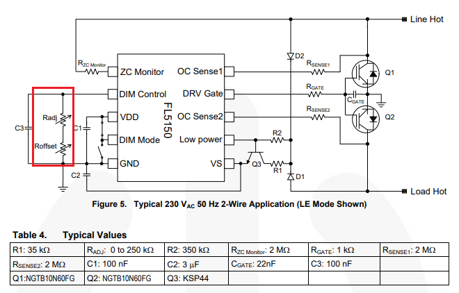
    0_1560755550927_661cc184-e1da-4245-8e3f-94ecb9736306-image.png

    I looked at a AD5241BRZ1M it has 256 steps from 0 to 1mio (it only needs 0 to 250 though, but the 200ohm seems to be too little, correct me if I'm wrong and the 250ohm are too expensive to my liking.

    Or is there another way of doing this?

    thnx!


  • @omemanti i did some digging, looks like a DAC will solve my problem. If it works I'll close this request. Fingers crossed.


  • Please report the results. I thought this dimmer chip looked interesting, but it seems to be optimized for manual control with a pot. Like you, I want something to control with MySensors.


  • @nagelc just bought some things to get me started, I have a fallback, just use digital resistors, in series, if needed.

    After reading the datasheet again, im not so sure the DAC will do the trick, it's the pull-down resistors that determine the voltage, so I think a DAC won't work.


  • Since the dimmerpin needs a resistor to ground. I placed a 1M ohm digital potentiometer and used it to controll the dimmer. so far it works (a bit).
    1M ohm is to much, so maybe I can get is working with just one or two 100k ohm.

    I solderen together a very rough setup, and I can dim the light using a pro-mini 3,3v.

    It still has some flickering, and I think I need to get a MOSFET or something to pull it to ground to turn the light off.

    But so far so good.


  • it's been a while. A short status update. I made a PCB and I'm testing the principals, but since I lack the time it will take a couple of months more 😑.

    First impressions, I can control the chip with a digital potentiometer. I use a 100K for dimming, and pull it to ground for shutdown.

    The 100K pot cost a couple of cents. Preferably you would use a 250K but those cost around 9 euros.

    I made some new PCB's for testing, I made some booboos with the first tests. But as I said, I'll be busy the next couple of months.


  • Banned

    This post is deleted!


  • I have been playing around with these Fl5150 with success. I've been using the DAC on ESP32 and an Op Amp and I can dim it up and down with an arduino sketch and also with home assistant via ESPhome. It's a work in progress at the moment but here is the Schematic https://easyeda.com/james_6977/fl5150-dimming-with-dac
    I intend on improving it to a more usable and safer point. In this version only 1 dimmer will work properly(it works good though, will turn off and you have good control over the level) if you try and use both there is some interference that makes them both not work properly.
    I've ordered a I2C DAC which would need a Op amp as it can sink to ground unlike the ESP32 DAC (I think??) and a I2C digital isolator so that I can try separating the 240v from the MCU and then 1 x MCU could potential control a number of dimmers, in my case 4 inside a control box I've made up.

    The Dual Op amp in this board I've made up, sinks the current that the FL5150 puts out of the DIM control pin to ground and ensures that the voltage at the DIM control pin remains at what ever the ESP32 DAC is producing on GPIO 26 and feeding into the OPamp non-inverting input.


  • @jimmyjames said in [Question:

    I intend on improving it to a more usable and safer point.

    Could you elaborate a bit on the last part, the safety issue; I think you mean that it is not a very safe circuit at the moment: No isolation between 230VAC and the microprocessor part or am I missing something?

    BR, boozz


  • @boozz Basically it comes down to the final application, and was just letting others know that, it is important to consider what will go where, how it will get used.
    With the schematic in it current form, 240v and the 5v side is not galvanically isolated, which is ok, as long as everything remains inside an insulated or earthed enclosure, and only 240v wires go in and out. That means you should not add external sensors or switches to the ESP32, which although they will work will be referenced to neutral or possibly line, which could create a potential hazard. I was considering using a I2c isolator to keep the ESP32 galvanically isolated from the FL5150 dimmer circuit, I have ordered the parts to try it too, the only downside is then you need a power supply for the ESP32 and isolated one and another power supply for the I2C isolator on the FL5150dimmer side as it uses upto 6mA 5vdc and the DAC use 1mA so that is inconvenient.
    I have a video of the lasted dimmer i've tried: https://youtu.be/bXHvo86CJp4


  • @jimmyjames said in Question: FL5150 LED Dimmer - replace a analog potentiometer with a digital one:

    ..., the only downside is then you need a power supply for the ESP32 and isolated one and another power supply for the I2C isolator on the FL5150dimmer side as it uses upto 6mA 5vdc and the DAC use 1mA so that is inconvenient.

    Have you considered using isolated DC-DC converters? Then you may be able to keep all in the concept of "only 240v wires go in and out".

    Will take a look at the video within short

    BR, boozz


  • Hero Member


  • @rvendrame Thanks for the circuit reference, it not exactly what I was after but useful to check out, in my researching. I'm looking at using a digital isolation IC to isolate the i2c signal and a DC to DC as @boozz suggested to power the isolstor and the DAC on the dimmer side that way only 1 power supply is required. The only thing is the the DC DC convert is $3 for a cheapy and $6 for something my substantial.


  • @jimmyjames Cool, I tried a DAC, but since my inexperience, I didn't get it to work with the FL5150.

    I just received the PCB's I ordered and use a 50K digi-Pot. But now I want to use the DAC.. 🙂
    Sofar:
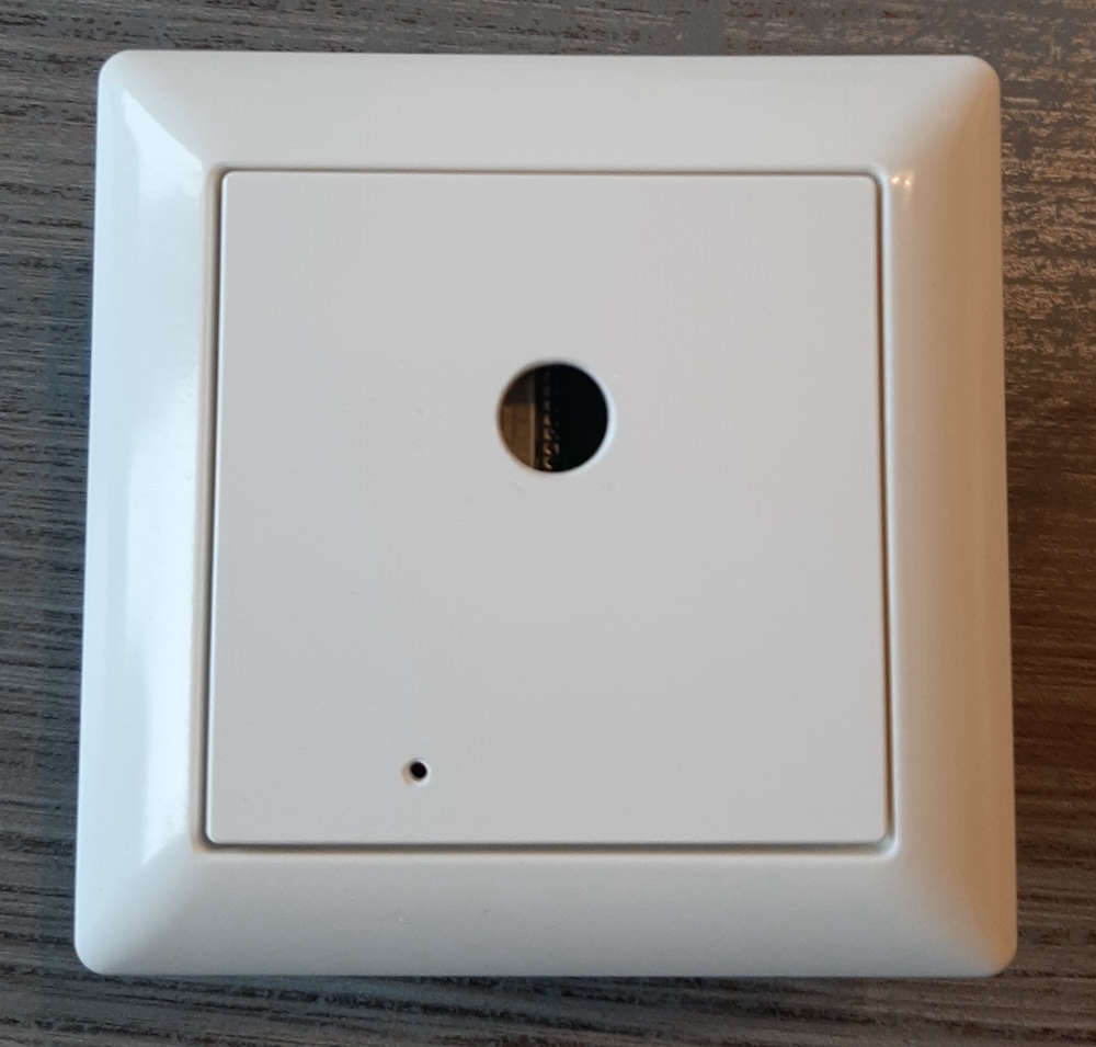
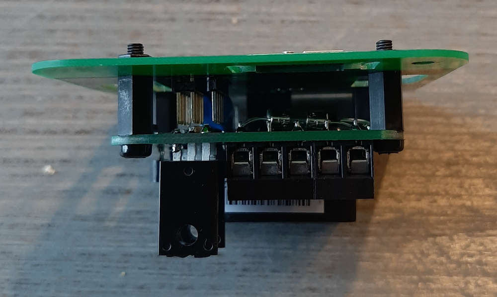
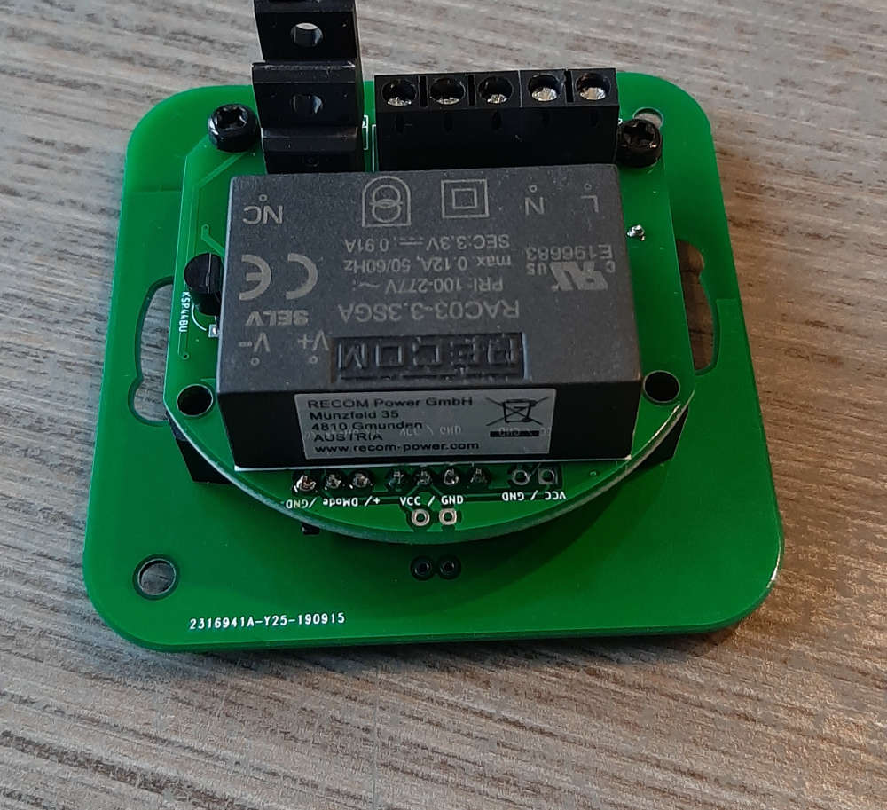
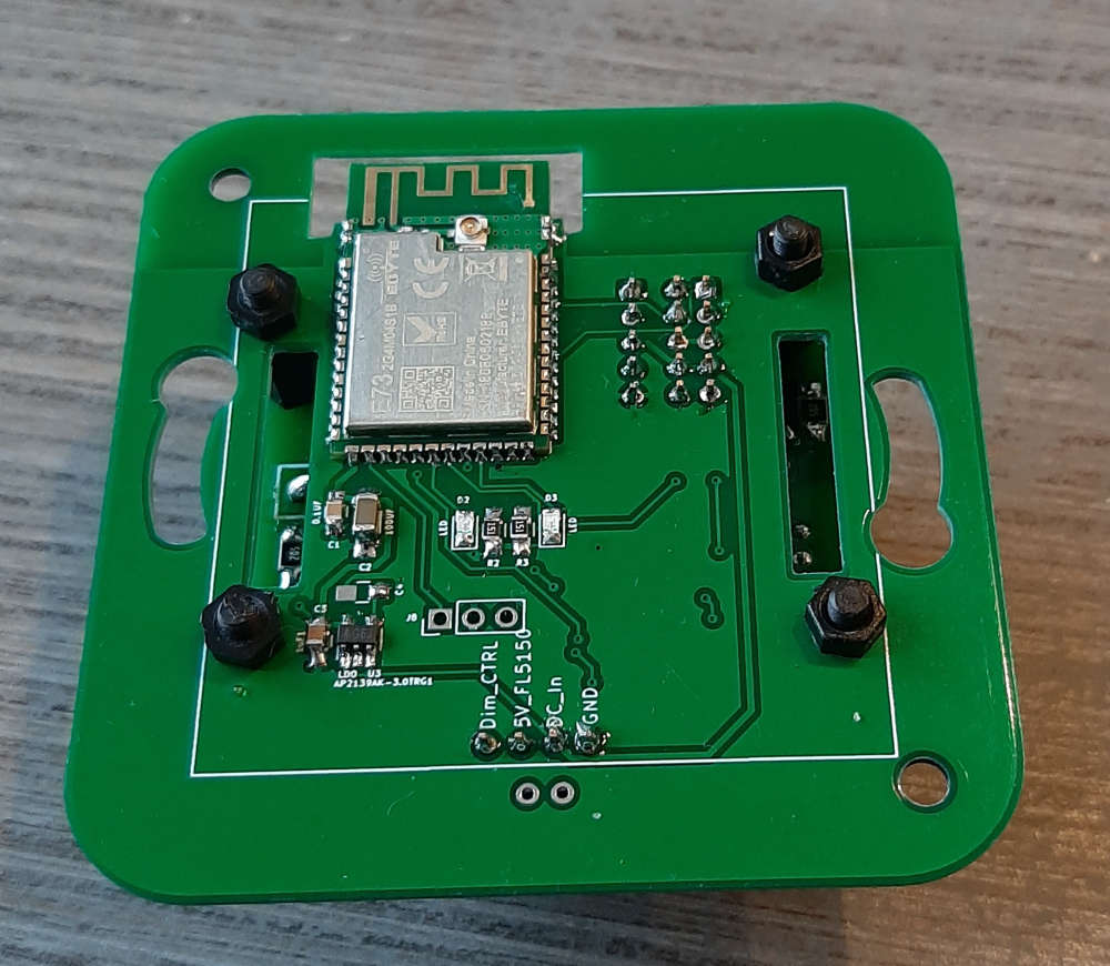
    3_1570260264539_20191005_083919.jpg 2_1570260264539_20191005_083833.jpg 1_1570260264538_20191005_083824.jpg 0_1570260264538_20191005_083819.jpg


  • I just registered here for this topic.
    I am planning to build a dimmer and I want it to be based on the FL5150 as the dimming controller and an arduino/atmega328 to control the FL5150

    I am not very confident in my understanding of this chip, so here's what I assume (btw: It would be nice if someone could :

    • DIM Control has an internal pullup resistor (otherwise the potentiometers would have to be used as a voltage divider between VDD and GND instead of just being connected to GND).
    • VDD can source at least some current for external components (otherwise it would be useless, since DIM Mode has a pullup resistor according to the datasheet so to choose between trailing and leading edge, you just have to either short DIM Mode to ground or leave it floating)

    Under those assumptions, my first idea was to drive a reasonably fast optocoupler with a PMW signal from my MCU and put that optocoupler between GND and DIM Control pins. Unfortunately, DIM Control is not suited for receiving a PMW signal (as per https://www.onsemi.com/PowerSolutions/faq.do?method=faqs&wpn=FL5150).

    Then I thought about adding a low pass filter between the optocoupler and DIM Control, but I'm worried I will end up with my signal being either too slow or too unsteady.

    So using a DAC or digital potentiometer sounds good, thanks for the idea. But since I have no knowledge of these components whatsoever, can anyone point me to the right one? I would like to have a DAC or digital pot that works with PWM instead of a serial connection, so I can still keep my optocoupler and have galvanic seperation between the high voltage AC and the low voltage DC parts of my circuit.


  • @mmgross

    I use a MCP4017T digital pot. the 50K one. I tested it, it worked. the dimming range isnt that great, but i think I have between 10% and 75% . To turn it off I have a mosfet to pull the DIMcontrol to GND and a mosfet to let DIMcontrol float (full on).

    since the range that I have is limited, im curious how the DAC will operate.

    When I look at the schematic from @jimmyjames, I see that he uses the mcp4716a0t-e/ch as DAC.


  • Hi!
    I want to start with these FL5150 dimmers and have some questions, hope you can help me.
    In the first post's diagram there are two pots inside the red rectangle, I asume that the 250k pot is the main one but can't understand what the 50k pot does. Maybe adjusting when the bulb shuts down?
    And would I need a switch for turning down the whole circuit when the bulb is off? Or is it enough just turning the bulb off using the pot.

    Thank you guys, hope you could understand what I meant. Still learning English.


  • @jimmyjames

    Hi,
    Hi everyone,

    I'm creating a project that will dim light circuits from a esp32 in trailing edge . I am very cautious about 240vac mixed in with low voltage.
    So im thinking about using this FL5150.
    FL5150 5 volts PS will be supplied from a 5 volt regulator circuit designed to be on the AC side with FL5150. Should be straight forward.
    Next use 4 opto couplers across a series R network to produce a DAC. So you have 4 bit to analog out. This gives me galvanic isolation from AC.
    4 bits gives 16 steps of voltage to Dim control line on FL5150.
    Would be very cheap in parts and piece of mind with separation on esp32 and AC.
    Any ideas if I'm on the right track ?


  • This post is deleted!


  • hi, @berton
    I'm also working on the same thing using ESP as the controller, trying to control FL5150. Firstly I made the dimming circuit using the adjustable resistors and I succeed with both dimming types(LE and TE). Now I'm trying to add microcontroller part to it.
    How can you place 4 optocouplers across series R network to produce DAC values? Is it to get isolation between AC ground and Digital ground?


  • @berton Hi, That is actually not a bad idea, in reality you don't really need 256 steps of dimming. Keep in mind that with the FL5150/60 that DIM control needs 0v (no resistance to ground, to put the FL5150 into low power mode or turn it off) . Also in the data sheet resistor R1which supplies power to the VS pin on the FL5150 needs to be greater than 0.125w as I found that the 1206 that I had connected was over heating, I'm not 100% sure why or if maybe a 1/4 resistor may be better.


  • @mmgross A digipot is not a bad idea, I found the DAC pretty easy via i2c but not all DACs will work on their own. The very first attempt I use the ESP32 DAC and blew it up, I tried again with the ESP32 DAC that powered an op-amp. That work pretty well. I tried a PWM with a low pass filter and an OP-amp but that wasn't easier and not vey accurate in setting the light level. Probably the best I idea is @berton using an optocouple an a resistor network/resistor ladder of sorts to make a 4 bit signal. The DIM control sources current a very small amount at 5v if you short it directly to ground at the dim control pin you will get 0v which is off, at various resistance you will get different dim levels, or you can use an op-amp which is always trying to make the output the same as it's input, that works too.
    VDD can't source anything worth using I have tried and also asked SemiON, you need to provide a power supply for any components you want to add, that is way so far a 4bit resistor network wins as that needs no power to operate on the isolated side.
    I have always been looking at the problem thinking that it need isolation, it doesn't, if all the components are safely kept away from human touch, there are MCUs that run at 3.3v in an environment that is not galvanically isolated.


  • @omemanti BTW - That is a great looking design you've made there it looks very good.👍


  • @jimmyjames said in Question: FL5150 LED Dimmer - replace a analog potentiometer with a digital one:

    a great looking design you've made there it looks very g

    Thnx, 🙂

    yesterday I finally installed my things after 2 months of moving. Going to try and make a new PCB using a NRF52 and the DAC you used. hopefully it will finally succeed to make a safe inwall socket.


  • If anyone else ends up here like I did.

    To drive the DIM Control pin without pulling from Vdd, try this.
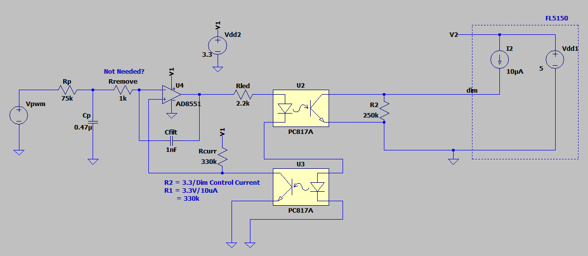
    faee2e57-e139-4488-be99-5ddd468df708-image.png

    This will keep the micro isolated. This assumes that you use a dual optoisolator, and that the CTR is the same. To ensure they ARE equally matched, you can buy the more expensive IL300 or LOC110 - built especially for this purpose.

    Also do note: if you are going to make a DUAL dimmer, then do NOT connect the 'GND' between dimmer A and dimmer B. They must be separate.


  • Hi, I found this post after trying to find designs for building a configurable forward/reverse phase dimmer controlled by ESP32.
    Has anybody by chance put the previous post in production, i.e. allowing for fully isolated use?
    Alternatively, are there other controllers like the FL5150 that can be controlled deterministically via e.g. I2C, PWM, etc.?


  • @ptr727 This chip will work for a single channel dimmer, but has trouble operating as part of a multi channel dimmer. I prototyped a one channel design and had it working but gave up as I could not get a workable design for a 4 channel unit.


  • The important thing to remember when making more than 1 channel - you cannot tie those GNDs together; they are NOT 0V and are NOT equal to each other. Call one GND_A and one GND_B. Or Bob and Greg. Each FL5150 must be separate. Which then means your microcontroller needs to be totally isolated. Which is where a digital potentiometer becomes very handy.


  • @ptr727 My design above did work. And it was 2 channel. But it did flicker a little. I'm going to try a digital potentiometer.


  • This post is deleted!


  • Hi @jimmyjames , I try to make a multi channel dimmer by myself based on your circuit.
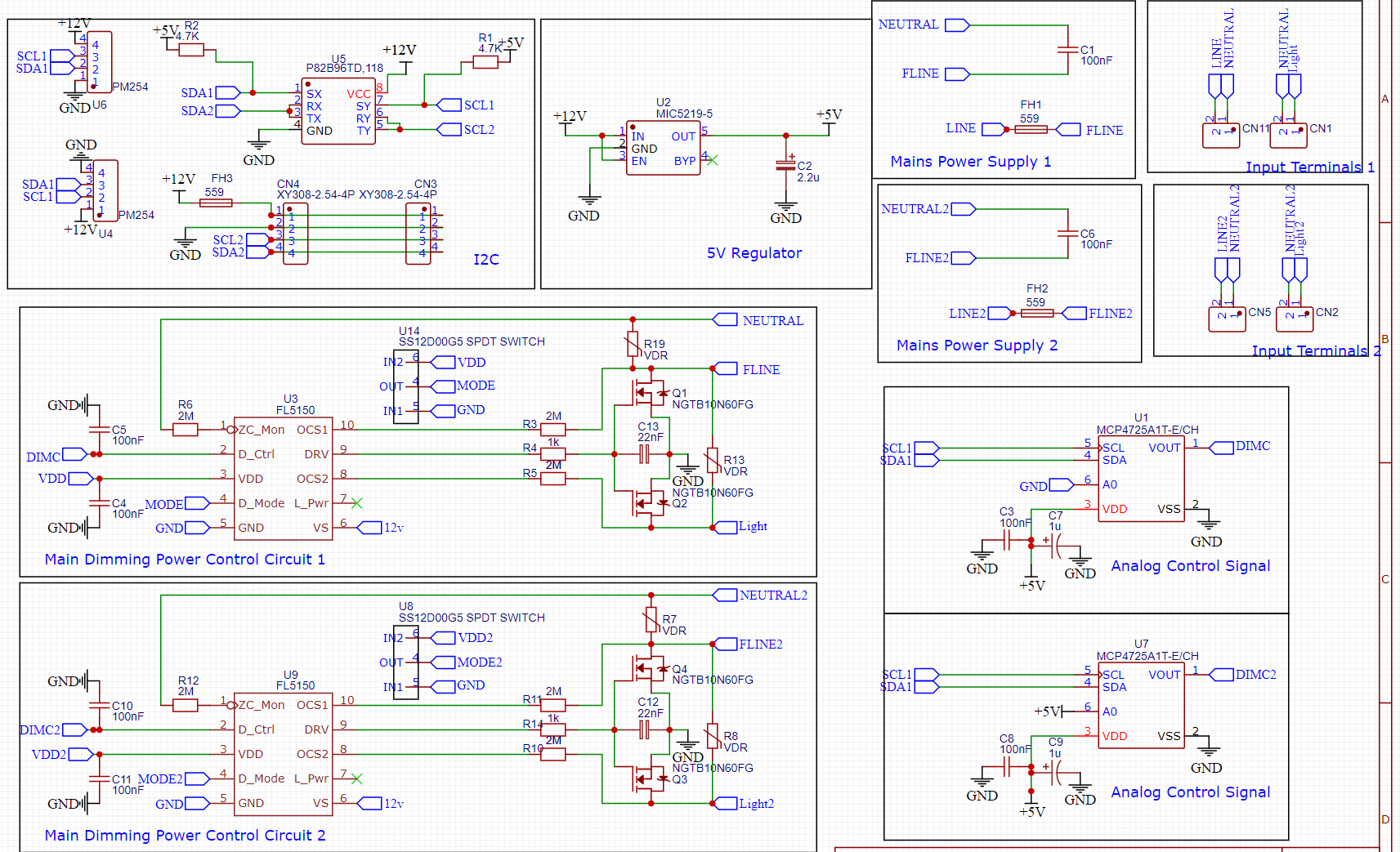
    2022-12-22_11-54-15.png

    So I want to use a shared 12V power supply that galvanic separated from mains for my dimmers and also a shared ESP32. But when I read these comments I can not use a common gnd for both channels? Is there a solution for this. So I don't need to have for every channel a different power supply?

    With the attiny84 I have a dimmer as well. With this design I can make multi channel dimmers because the mains is completely isolated from the DC part.
    See picture:
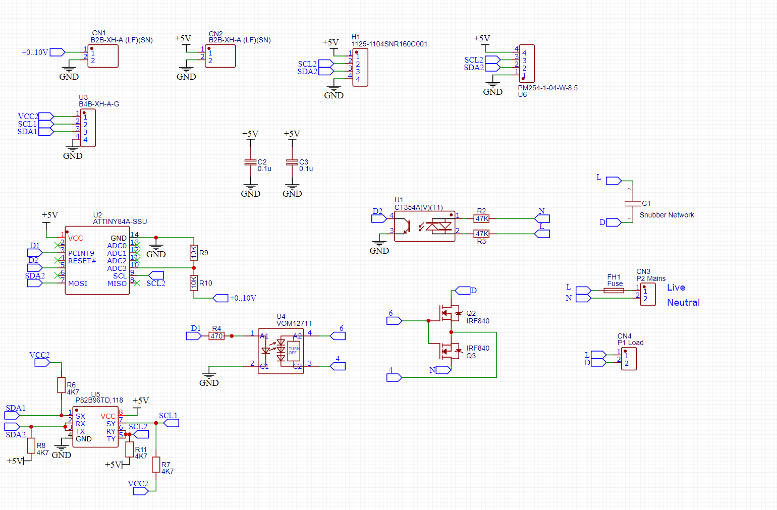
    2022-12-22_12-01-10.png
    Another advantage is that the I2C addresses can be programmed in the attiny so I am not limited in the number of addresses.
    But when testing this approach I have not that good results in the low dimming , my led bulbs are flickering. So I want to try if the fl5150 is doing a better job.
    The flickering starts if I am dimming at 15% .
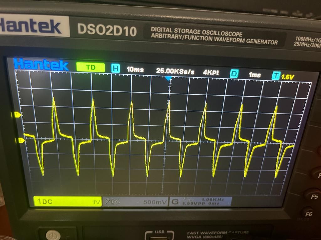
    See the oscilloscope pictures:
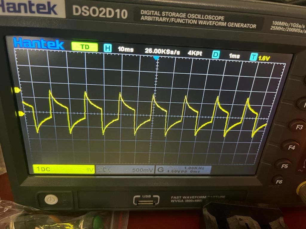
    flickering.jpg
    not flickering.jpg

    First one is if I dim at low percentage then the flickering starts.
    The second one is at a level when flickering stops.

    Do you think the FL5150 will do here a better job, or can my circuit of the attiny84 being improved to get the dimming correct at the lower levels?

    BR,
    Edwin


  • I just tested 2 led types with no flicker on my attiny circuit.
    It is funny, the expensive leds like from philips: Dimmable 3.8W Warm White have a flickering behavior .
    A cheap one available in Action from LSC 6.3W, Dim to Warm and 460 Lumen has no flickering behavior.
    Another one from Osram Par 1650: 5.5W Dimmable Warm White, 350 Lumen also has no flickering.
    The philips has the best Energy savings though : 4kWh compared to 7kWh for the LSC one.
    Is there a relation between energy savings and dim quality ?


Log in to reply
 

Suggested Topics

  • 87
  • 3
  • 5
  • 10
  • 2
  • 1

50
Online

11.5k
Users

11.1k
Topics

112.7k
Posts