Sensor shield for Arduino Pro Mini 3.3V with boost up regulator
-
Hello,
I've been reading here for quite a while and now I want to share my idea of a project with you. I love all the wonderful projects that are shown here, but I wanted to have a shield, where I can put an Arduino pro mini (china clone) and NRF24L01+ into and have connections for sensors outside together with a boost up regulator so I can use 1 or 2 cells for powering.
Here is what I came up with. I really like to hear your ideas and suggestions, I tried to incorporate as many ideas and thoughts that I found elsewhere on this forum. It's actually the first time, that I'm trying to make my own pcb.Here's the scheme:
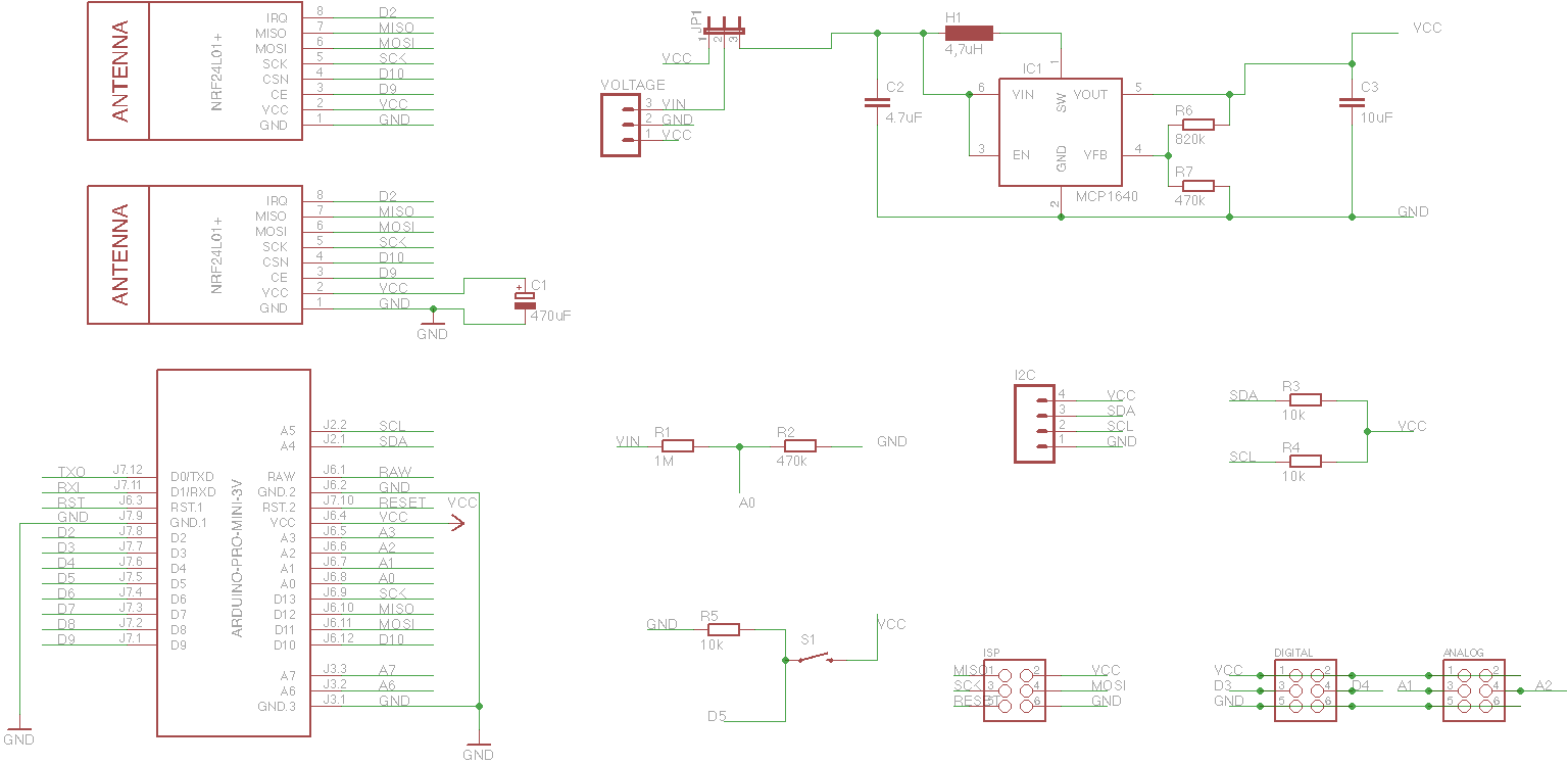
So these are the parts:
-
arduino pro mini 3.3V (china clone, have to remove voltage regulator and led)
-
two places to plug in the NRF24L01+ module (in both cases the antenna will not be covered by the shield pcb)
-
for voltage regulation, there is a MCP1640 (less power consumption than NCP1402 when everything is asleep)
-
a voltage divider on A0 to check battery voltage
-
a push button on D5
-
ISP port for programming
-
I2C port with pull-ups on SDA and SCL
-
two digital (D3 & D4) and two analog (A1 & A2) pins together with GND and VCC for sensors on 3-pin connectors
So my first pcb would look like this:
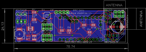
Size is 2.4 x 7.9 cm, it could be smaller but I need space for SMD soldering.
What do you think? Is the design worth sending to China for pcb manufacturing or do you have any ideas how to make it better?Thanks a lot,
Philipp -
-
Hello,
I've been reading here for quite a while and now I want to share my idea of a project with you. I love all the wonderful projects that are shown here, but I wanted to have a shield, where I can put an Arduino pro mini (china clone) and NRF24L01+ into and have connections for sensors outside together with a boost up regulator so I can use 1 or 2 cells for powering.
Here is what I came up with. I really like to hear your ideas and suggestions, I tried to incorporate as many ideas and thoughts that I found elsewhere on this forum. It's actually the first time, that I'm trying to make my own pcb.Here's the scheme:
So these are the parts:
-
arduino pro mini 3.3V (china clone, have to remove voltage regulator and led)
-
two places to plug in the NRF24L01+ module (in both cases the antenna will not be covered by the shield pcb)
-
for voltage regulation, there is a MCP1640 (less power consumption than NCP1402 when everything is asleep)
-
a voltage divider on A0 to check battery voltage
-
a push button on D5
-
ISP port for programming
-
I2C port with pull-ups on SDA and SCL
-
two digital (D3 & D4) and two analog (A1 & A2) pins together with GND and VCC for sensors on 3-pin connectors
So my first pcb would look like this:
Size is 2.4 x 7.9 cm, it could be smaller but I need space for SMD soldering.
What do you think? Is the design worth sending to China for pcb manufacturing or do you have any ideas how to make it better?Thanks a lot,
Philipp@phil83 Well I don't know much about the MCP1640. It was tested here: http://www.eevblog.com/forum/projects/working-with-mcp1640-boost-converter-high-iq-at-low-load/
It is probably fine. Pretty cheap but it's annoying having those two extra resistors on the board. Other than that you could shrink your inductor and capacitors a little. They look a little big. And spaced quite far apart? Soldering shouldn't be difficult as long as you do them all in the right order so you wont obstruct yourself.That surface mount electrolytic ... 470uF? Higher capacitance would yield lower ESR sure, but wouldn't a simple ceramic 4.7/10uF or whatever work just as well? Conveniently the same type also used for the boost regulator.
-
-
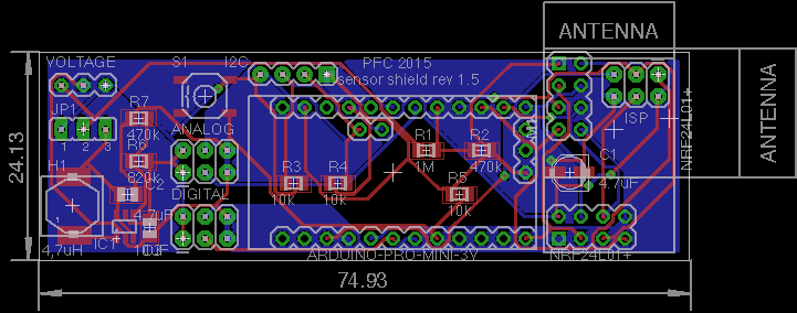
@bjornhallberg Thanks for your input! I used that inductor since I can get it quite cheap and it is shielded. I tried to space the capacitors closer to the MCP, the resistors are quite far away - thats right, but they only deliver the voltage to put the MCP into 3.3V output mode, so this should be fine. Regarding the electrolytic capacitor - 470uF was a mistake of mine, I wanted to use 4.7uF as shown on the mysensors main page - they also use an electrolytic one. So now I put in a smaller one. With your input I could shrink the pcbs to 2.4x7.4cm, thank you once again!
I checked prices yesterday and should have a final price of 5-6$ for pcb with parts but without arduino and nrf.
Have a nice sunday,
Philipp -
@bjornhallberg Thanks for your input! I used that inductor since I can get it quite cheap and it is shielded. I tried to space the capacitors closer to the MCP, the resistors are quite far away - thats right, but they only deliver the voltage to put the MCP into 3.3V output mode, so this should be fine. Regarding the electrolytic capacitor - 470uF was a mistake of mine, I wanted to use 4.7uF as shown on the mysensors main page - they also use an electrolytic one. So now I put in a smaller one. With your input I could shrink the pcbs to 2.4x7.4cm, thank you once again!
I checked prices yesterday and should have a final price of 5-6$ for pcb with parts but without arduino and nrf.
Have a nice sunday,
Philipp@phil83 I think the 4.7uF electrolytic is a bad recommendation for this purpose. It has been discussed a couple of times but the recommendation hasn't been changed. Probably because no one has actually tested and come up with a solution that is proven. It doesn't really matter though, you could retrofit any cap you want later. I've mostly put 1206 ceramic no-name caps on mine, soldered between to the nrf24 pins themselves and it seems to work. But I have no oscilloscope or esr meter or anything so it is impossible to know what is going on.
-
@bjornhallberg thanks for the advice, I searched the web and now I'm most likely to use a 100uF tantalum capacitor close to the two female pin headers for the nrf24l01 module. Thank you!
-
Hi, just looking at the step up voltage converter MCP1640 that you've specified. This has a quiescent current of 19uA. Perhaps you could consider switching to something with lower quiescent current such as the Texas Instruments TPS61221 which has previously been suggested for use on the official MySensors Battery Board (which still seems to be a work in progress) which only consumes 5.5uA. Don't know what the cost difference is though.
Cheers
Richard -
Yeah, my concern with the MCP1640 is that the link I posted to eevblog is on to something and that it is misbehaving. They never seemed to hit their uA targets, though it may be user error.
My main motivation for other regulators though, like the TPS61221, is that you need two less components, and thus less board space. I think the TPS61221 is about twice as expensive as the MCP1640. And the LTC3525 is about twice as expensive as the TPS61221. Those are the only regulators I have on hand, but there have been MANY more discussed in various posts. For me it is convenient that both the TPS61221, LTC3525 (and MCP1640) are available on AliExpress so I can avoid expensive shipping costs and probable customs fees.
-
Hello,
I've been reading here for quite a while and now I want to share my idea of a project with you. I love all the wonderful projects that are shown here, but I wanted to have a shield, where I can put an Arduino pro mini (china clone) and NRF24L01+ into and have connections for sensors outside together with a boost up regulator so I can use 1 or 2 cells for powering.
Here is what I came up with. I really like to hear your ideas and suggestions, I tried to incorporate as many ideas and thoughts that I found elsewhere on this forum. It's actually the first time, that I'm trying to make my own pcb.Here's the scheme:
So these are the parts:
-
arduino pro mini 3.3V (china clone, have to remove voltage regulator and led)
-
two places to plug in the NRF24L01+ module (in both cases the antenna will not be covered by the shield pcb)
-
for voltage regulation, there is a MCP1640 (less power consumption than NCP1402 when everything is asleep)
-
a voltage divider on A0 to check battery voltage
-
a push button on D5
-
ISP port for programming
-
I2C port with pull-ups on SDA and SCL
-
two digital (D3 & D4) and two analog (A1 & A2) pins together with GND and VCC for sensors on 3-pin connectors
So my first pcb would look like this:
Size is 2.4 x 7.9 cm, it could be smaller but I need space for SMD soldering.
What do you think? Is the design worth sending to China for pcb manufacturing or do you have any ideas how to make it better?Thanks a lot,
Philipp@phil83
Why not put the pro mini circuitry on the board in the first place? -
-
@GaryStofer What do you mean by putting the mini circuitry on the board? You mean just use an Atmega328 instead of the Pro Mini board? The reason for this is that the Pro Mini nearly costs as much as the parts and my soldering skills are not good enough to solder the Atmega directly onto the board.
I had to create a new user name - I can't log into the old any more, the password reset feature is also not working - sorry. -
@hawk_2050 @bjornhallberg Thanks for the information about the TPS61221. I checked the data sheet and also checked availability at AliExpress. I guess I'm going to switch to that one.
-
Yeah, you're probably not saving a whole lot of money doing your own arduino-like board from scratch. Can't seem to find cheap ATMEGA328P-MU on AliExpress either, only ATMEGA328P-AU. But then to really save space you'd have to use the "mini" nrf24 module as well.
-
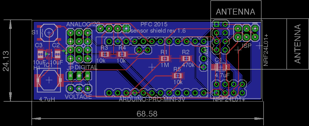
@bjornhallberg Yes, I totally agree... I could save probably 2cm in length of the board but have much more to solder.
-
Just curious - if Vin < VCC, why are you using a voltage divider to get the battery voltage? If you are using VCC as the ADC reference, you should be good without a divider, I'd think.
It would be possible to use the 1.1v internal reference (ONLY when measuring battery, not most sensors), in which case your divider could make sense, and that would remove the stability of the VCC power supply from the measurement - tho I rarely see that approach taken.
-
@maha Yes you're right, they are quite close... but they should be fine with my manufacturer. I'll try tonight to see what I can do to get the traces a little more apart, let's see. When I use the Gerber file, I can't find any spots where the lines are touching. The picture taken directly from Eagle is also probably not that accurate.
