Skip to content
  • MySensors
  • OpenHardware.io
  • Categories
  • Recent
  • Tags
  • Popular
Skins
  • Light
  • Brite
  • Cerulean
  • Cosmo
  • Flatly
  • Journal
  • Litera
  • Lumen
  • Lux
  • Materia
  • Minty
  • Morph
  • Pulse
  • Sandstone
  • Simplex
  • Sketchy
  • Spacelab
  • United
  • Yeti
  • Zephyr
  • Dark
  • Cyborg
  • Darkly
  • Quartz
  • Slate
  • Solar
  • Superhero
  • Vapor

  • Default (No Skin)
  • No Skin
Collapse
Brand Logo
  1. Home
  2. My Project
  3. Sensor shield for Arduino Pro Mini 3.3V with boost up regulator

Sensor shield for Arduino Pro Mini 3.3V with boost up regulator

Scheduled Pinned Locked Moved My Project
39 Posts 11 Posters 27.3k Views 6 Watching
  • Oldest to Newest
  • Newest to Oldest
  • Most Votes
Reply
  • Reply as topic
Log in to reply
This topic has been deleted. Only users with topic management privileges can see it.
  • m26872M m26872

    @Zeph
    I think you're wrong. The divider works perfectly when measuring against internal reference like shown at the build-site. I think it's very well proven and I have never had any issues. And this is for battery voltage LOWER than Vcc.
    I think I had a link to one of my code example here as well.
    But sure, if you have a stable and known Vcc you could use that as reference instead. Without divider.

    @phil83
    Why don't you use the recommended 0.1uF capacitor in parallel with R2 ?

    Z Offline
    Z Offline
    Zeph
    Hero Member
    wrote on last edited by
    #28

    @m26872 As I said in the first post, if you measure against the internal 1.1v reference (rather than the more common Vcc), it can work. And I see that's in fact what you are doing, so no problem, carry on.

    1 Reply Last reply
    0
    • P Offline
      P Offline
      phil83
      wrote on last edited by phil83
      #29

      Hey folks,

      I just received my first boards today. They really look nice, I never believed that it is so easy! Especially the manufacture in china was pretty cheap and looks really good. I had to wait four weeks, nearly perfect!

      pcb_16042015 Kopie.jpg

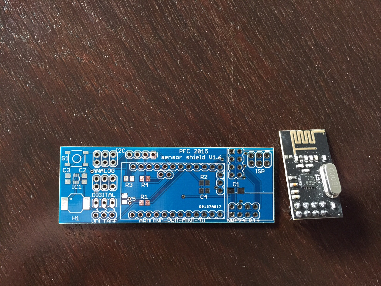
      Now I'm waiting for two more capacitors, all the other parts were delivered already. I hope to be able to solder next week and will keep you updated afterwards!
      I think I got infected by a virus by now since I'm already planning the next board ;-).

      Thanks again for all your help,
      Philipp

      1 Reply Last reply
      2
      • M Offline
        M Offline
        Mickey
        wrote on last edited by
        #30

        Very nice board.
        Do you intend to share gerber files/eagle file?

        1 Reply Last reply
        0
        • P Offline
          P Offline
          phil83
          wrote on last edited by
          #31

          I'm going to check the board in the next few weeks, when everything is fine, I will share...

          1 Reply Last reply
          0
          • P Offline
            P Offline
            phil83
            wrote on last edited by
            #32
            This post is deleted!
            1 Reply Last reply
            0
            • P Offline
              P Offline
              phil83
              wrote on last edited by phil83
              #33
              This post is deleted!
              1 Reply Last reply
              0
              • G Offline
                G Offline
                gloob
                wrote on last edited by
                #34

                Hello,

                I would be interessted in the wiring diagram, as I want to build something similar but with no SMD parts.
                Would you share your actual diagram please?

                Thanks,
                Stefan

                1 Reply Last reply
                0
                • P Offline
                  P Offline
                  phil83
                  wrote on last edited by
                  #35

                  Hi everyone,

                  I received the last parts on monday and populated 2 boards so far. I found out, that one header for nrf24 is not working properly... most likely since the wires are too far away from the capacitor. The other header is working perfect. Here are the first pictures of the populated board:

                  PFC sensor shield 1.6 A.jpg

                  PFC sensor shield 1.6 B.jpg

                  PFC sensor shield 1.6 C.jpg

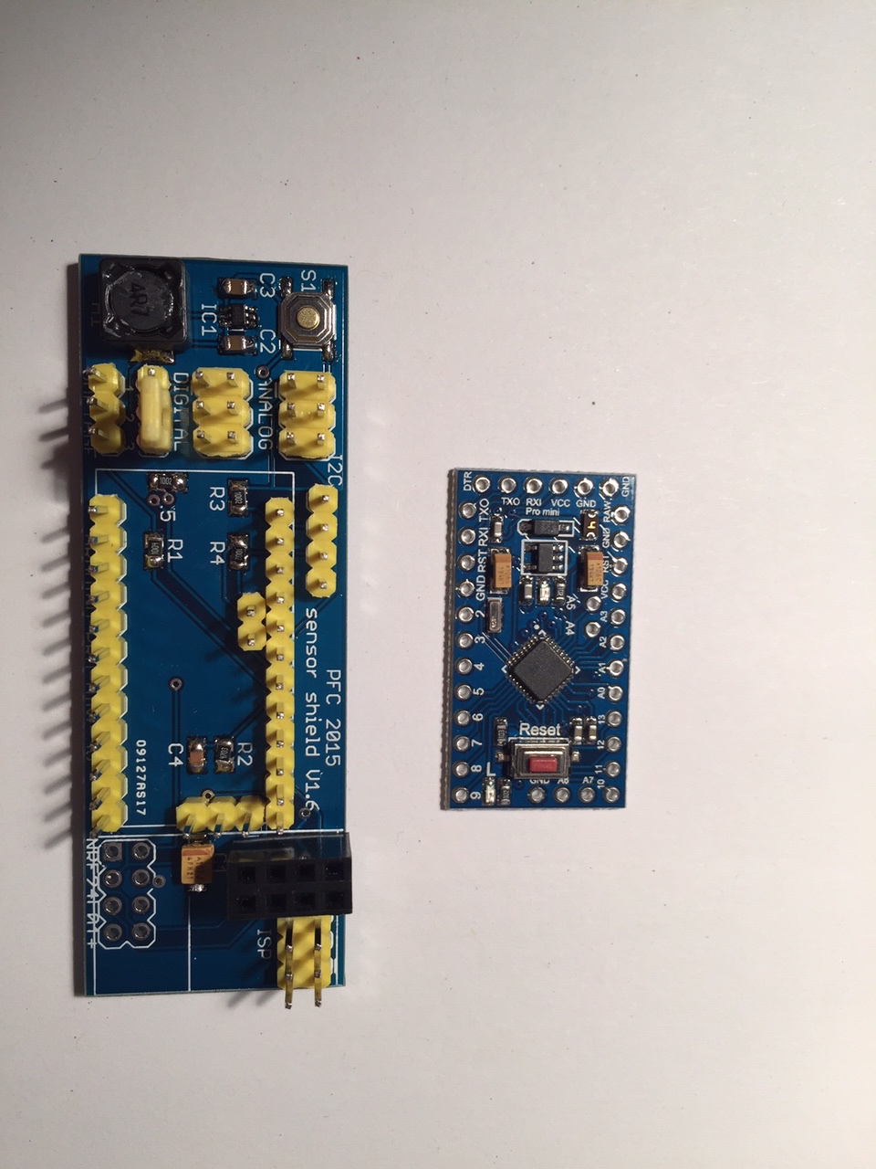
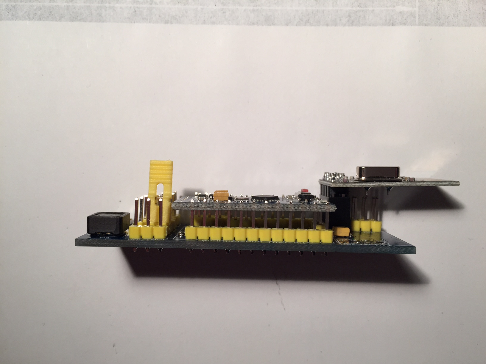
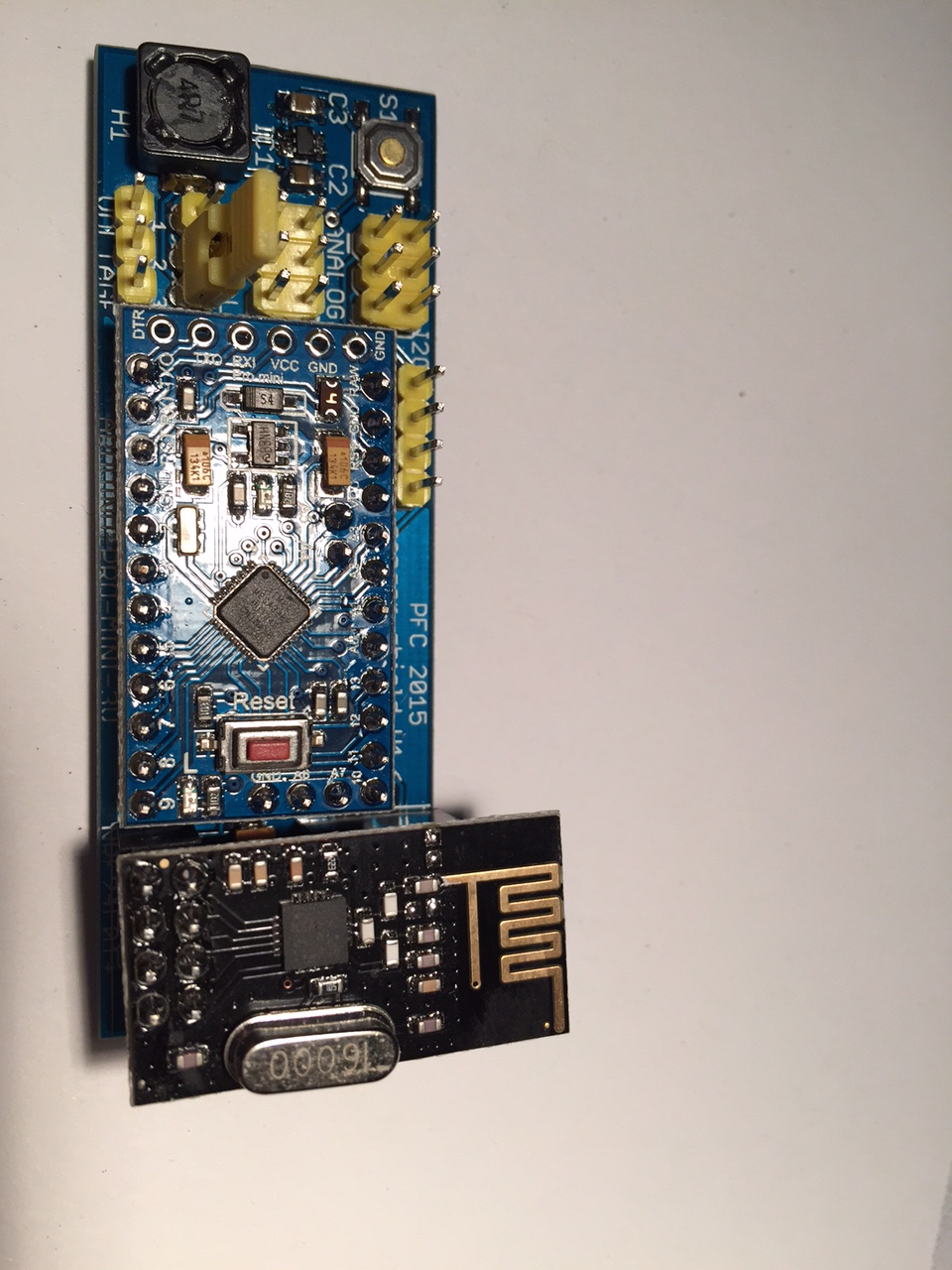
                  Though the hand soldering of the sot23-6 was not easy at all, I managed to do it. I tested the boards with the BatteryPoweredSensor and the voltage divider is working properly. I will now start to program more and see which sensor I can build with that board.

                  Thanks again for all your help,
                  Philipp

                  1 Reply Last reply
                  2
                  • P Offline
                    P Offline
                    phil83
                    wrote on last edited by
                    #36

                    @gloob : The scheme shown above is still the same, I only added a capacitor in parallel to the voltage divider!

                    1 Reply Last reply
                    0
                    • M Offline
                      M Offline
                      Mickey
                      wrote on last edited by
                      #37

                      turn out very nice.
                      are you planing to share eagle files?

                      1 Reply Last reply
                      0
                      • bjornhallbergB Offline
                        bjornhallbergB Offline
                        bjornhallberg
                        Hero Member
                        wrote on last edited by
                        #38

                        Great work! Really impressive!

                        1 Reply Last reply
                        0
                        • P Offline
                          P Offline
                          phil83
                          wrote on last edited by
                          #39

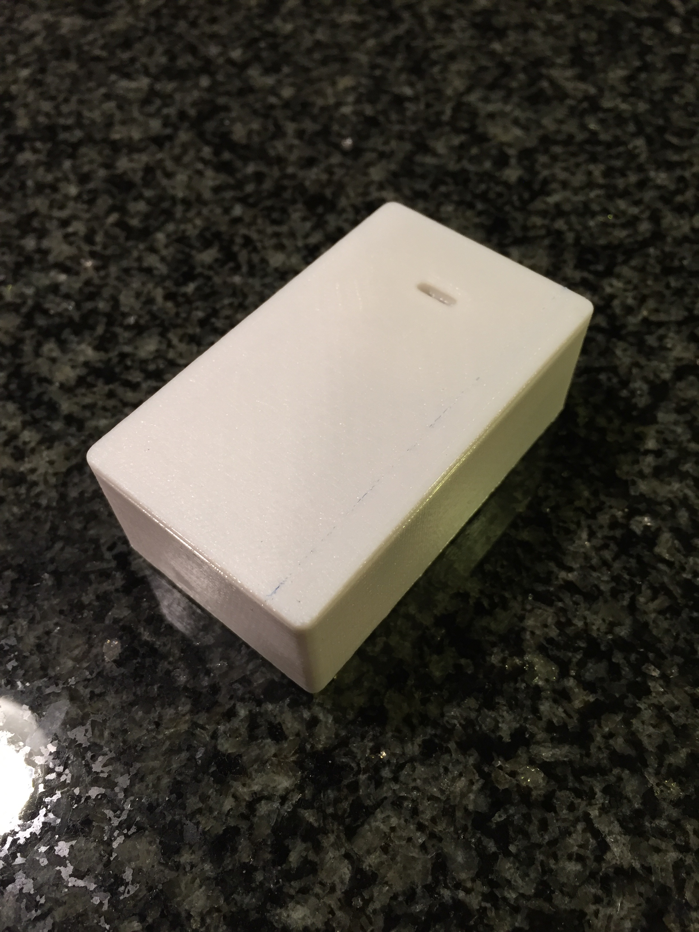
                          Long time no see... I had time to work on my sensors lately and here are some pictures of my humidity sensor which is running here for three months now:

                          0_1454090300302_IMG_00061.jpg
                          0_1454090355121_IMG_00041.jpg
                          0_1454090545068_IMG_00031.jpg

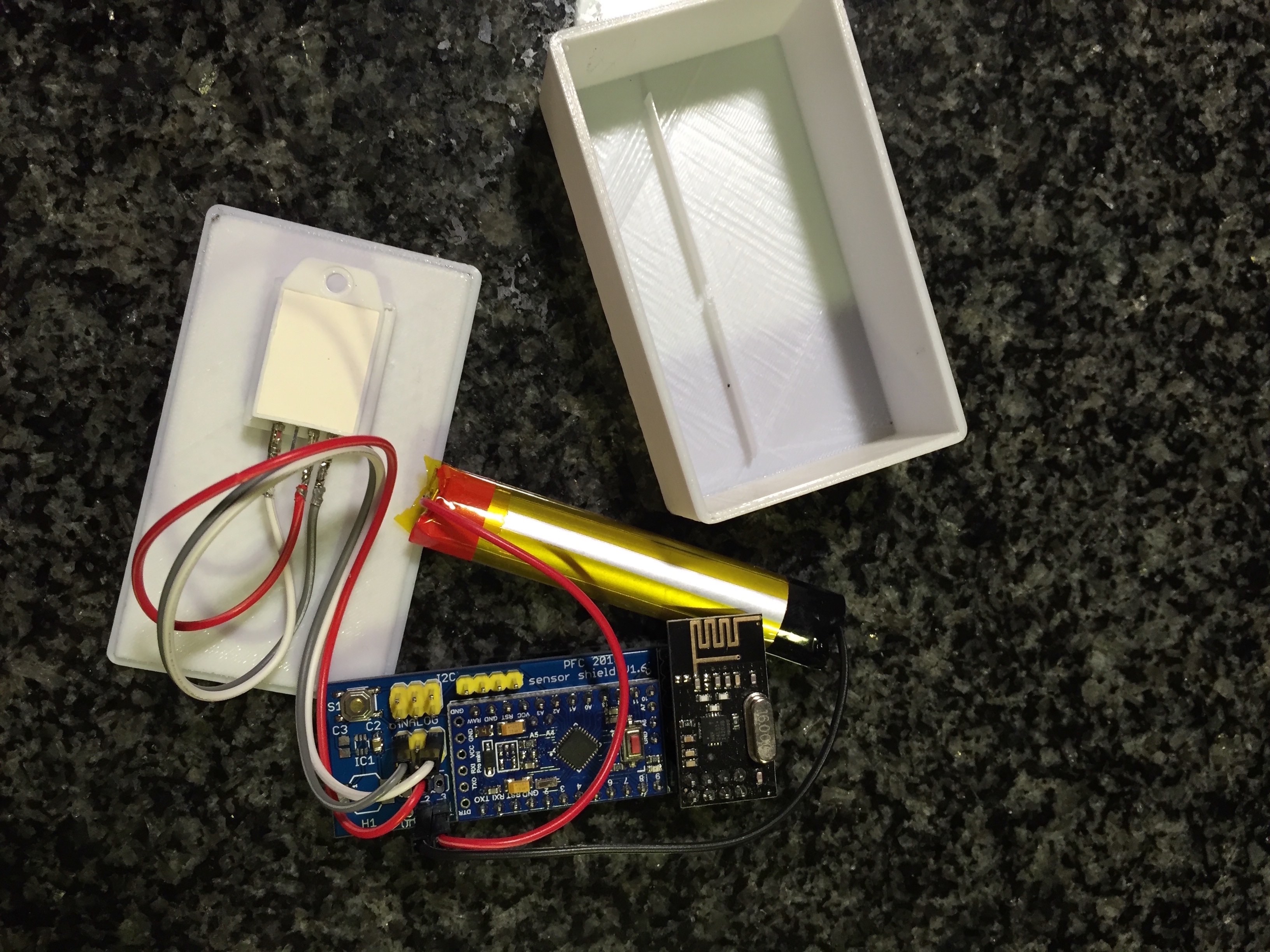
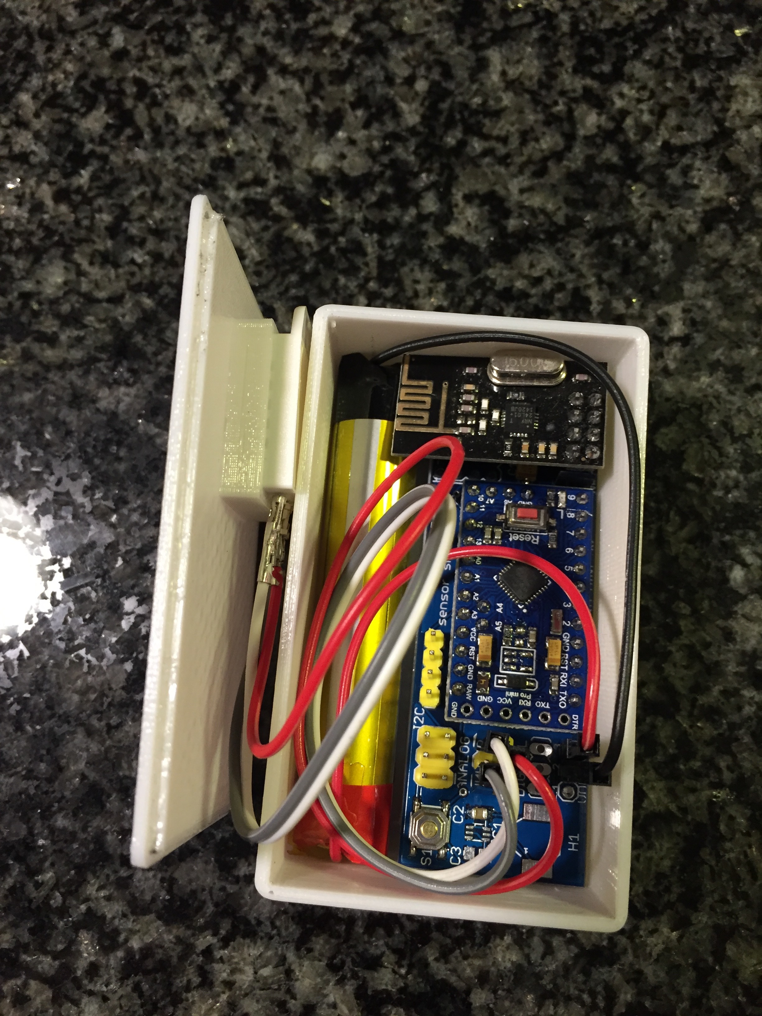
                          I left out the power regulator shown above and also desoldered the LED and voltage regulator of the Arduino to safe power. The sensor is directly powered by 3.7V of the lithium battery. The voltage is measured and the battery will be recharged when it goes down.
                          Since I also built a 3D printer lately, I was able to put the sensor into a little box. Now I can easily measure humidity and temperature in my bath room and see it in fhem on a raspberry.

                          Currently I'm working on my next pcb... I will show the next one when I'm finished in a new thread.

                          1 Reply Last reply
                          1
                          Reply
                          • Reply as topic
                          Log in to reply
                          • Oldest to Newest
                          • Newest to Oldest
                          • Most Votes


                          8

                          Online

                          11.7k

                          Users

                          11.2k

                          Topics

                          113.0k

                          Posts


                          Copyright 2019 TBD   |   Forum Guidelines   |   Privacy Policy   |   Terms of Service
                          • Login

                          • Don't have an account? Register

                          • Login or register to search.
                          • First post
                            Last post
                          0
                          • MySensors
                          • OpenHardware.io
                          • Categories
                          • Recent
                          • Tags
                          • Popular