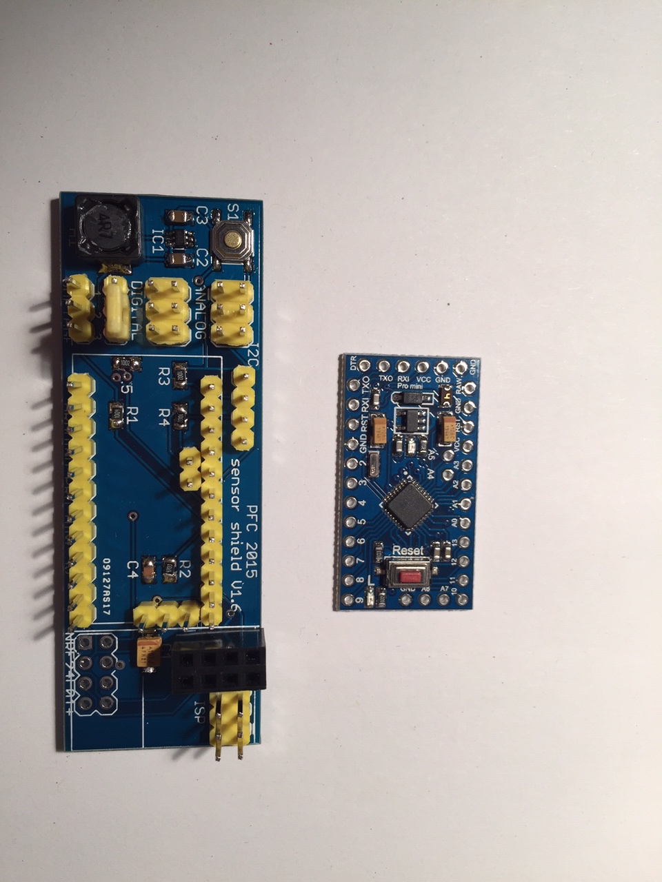
Sensor shield for Arduino Pro Mini 3.3V with boost up regulator
-
Hi everyone,
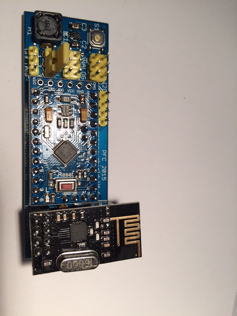
I received the last parts on monday and populated 2 boards so far. I found out, that one header for nrf24 is not working properly... most likely since the wires are too far away from the capacitor. The other header is working perfect. Here are the first pictures of the populated board:
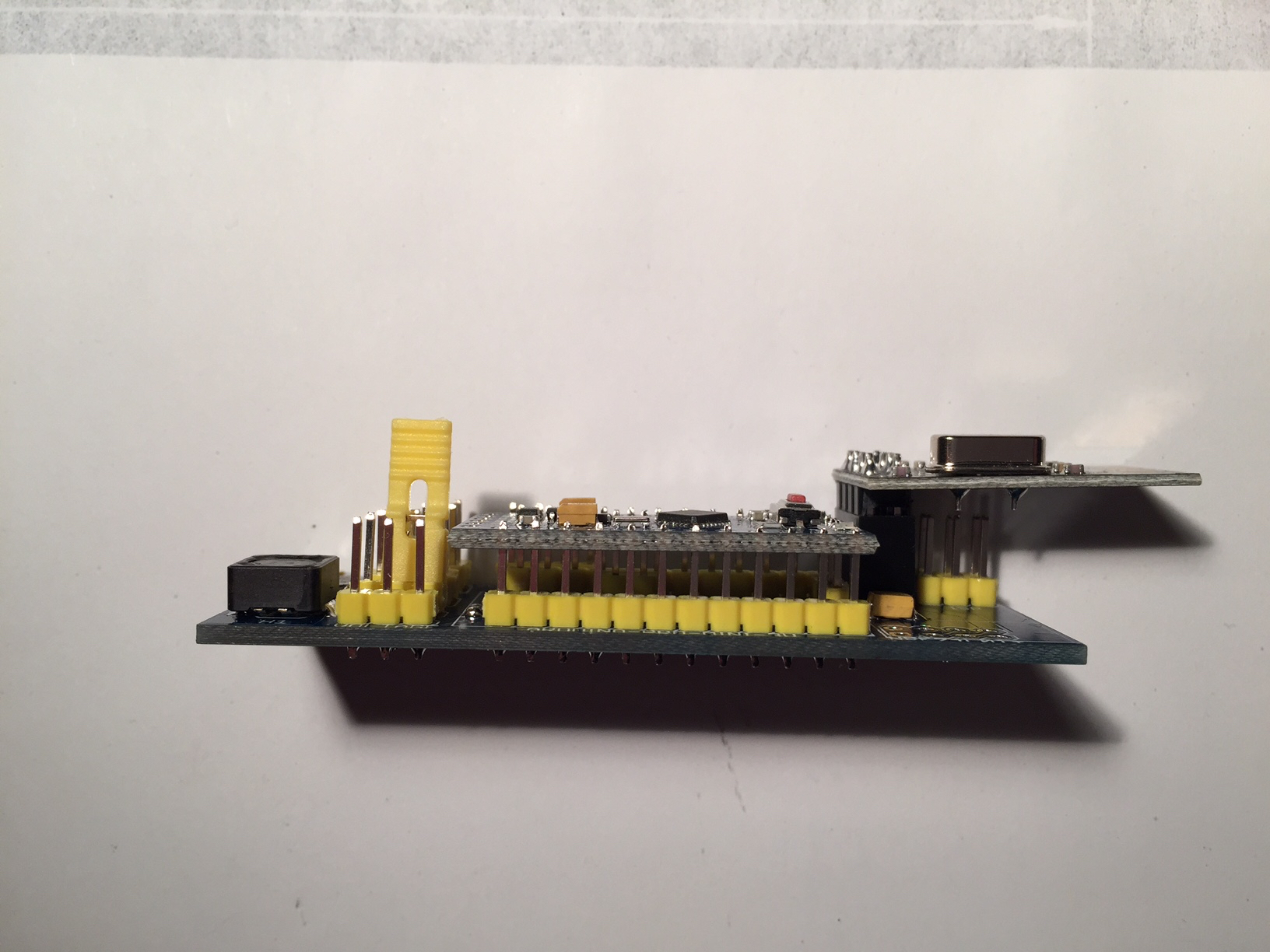
Though the hand soldering of the sot23-6 was not easy at all, I managed to do it. I tested the boards with the BatteryPoweredSensor and the voltage divider is working properly. I will now start to program more and see which sensor I can build with that board.
Thanks again for all your help,
Philipp -
Great work! Really impressive!
-
Long time no see... I had time to work on my sensors lately and here are some pictures of my humidity sensor which is running here for three months now:
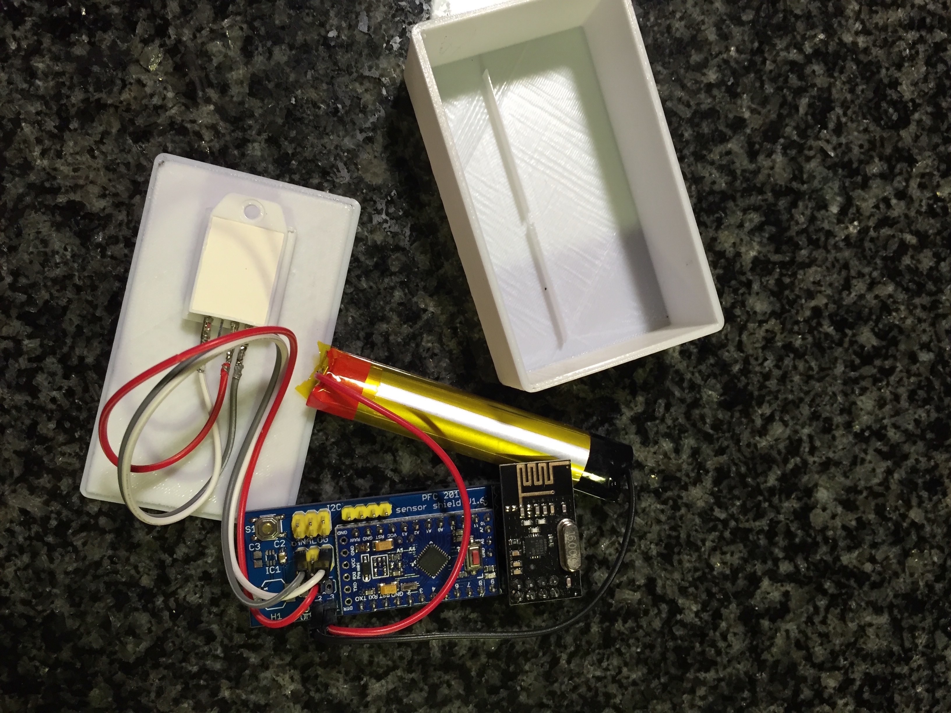
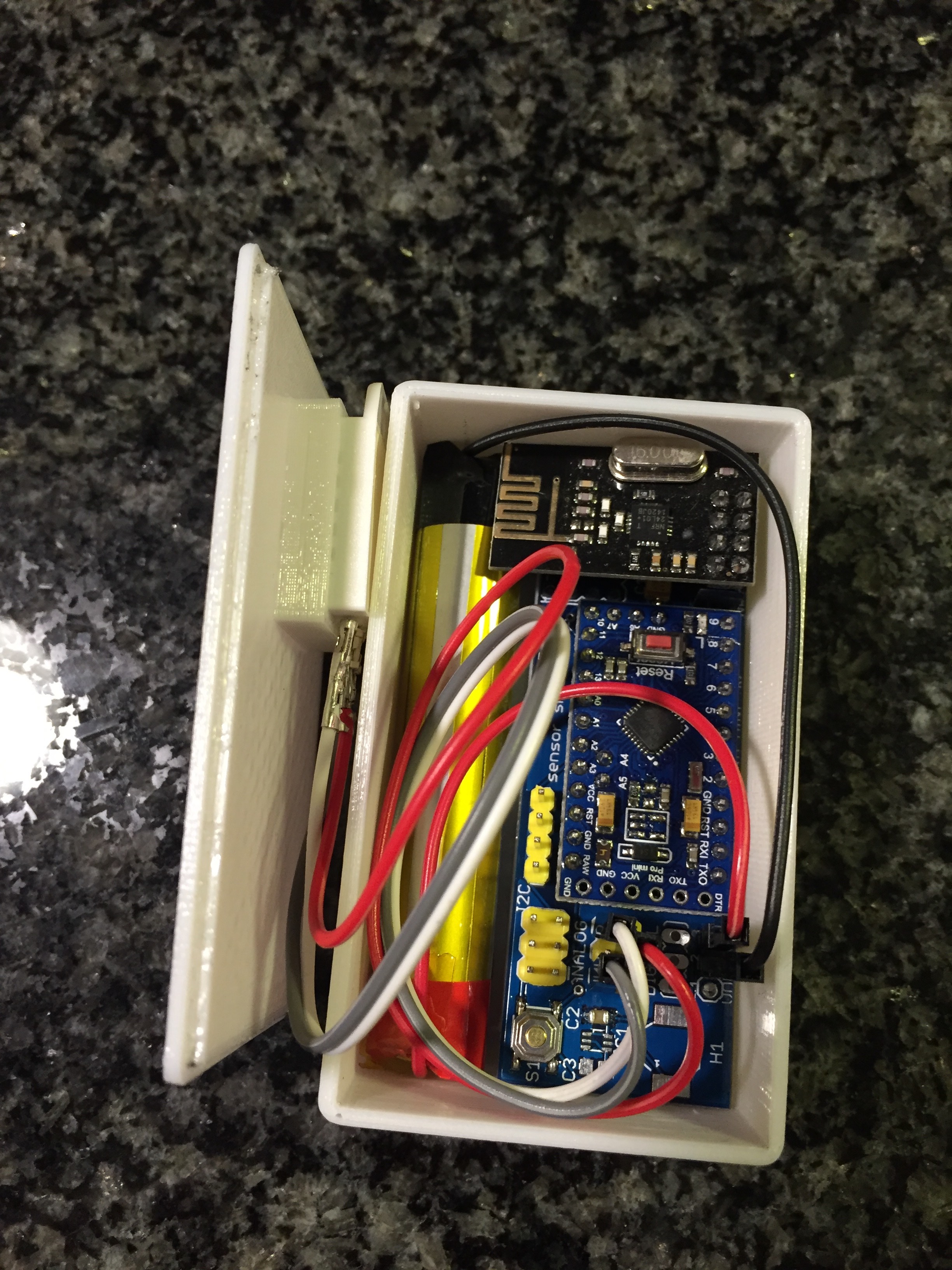
I left out the power regulator shown above and also desoldered the LED and voltage regulator of the Arduino to safe power. The sensor is directly powered by 3.7V of the lithium battery. The voltage is measured and the battery will be recharged when it goes down.
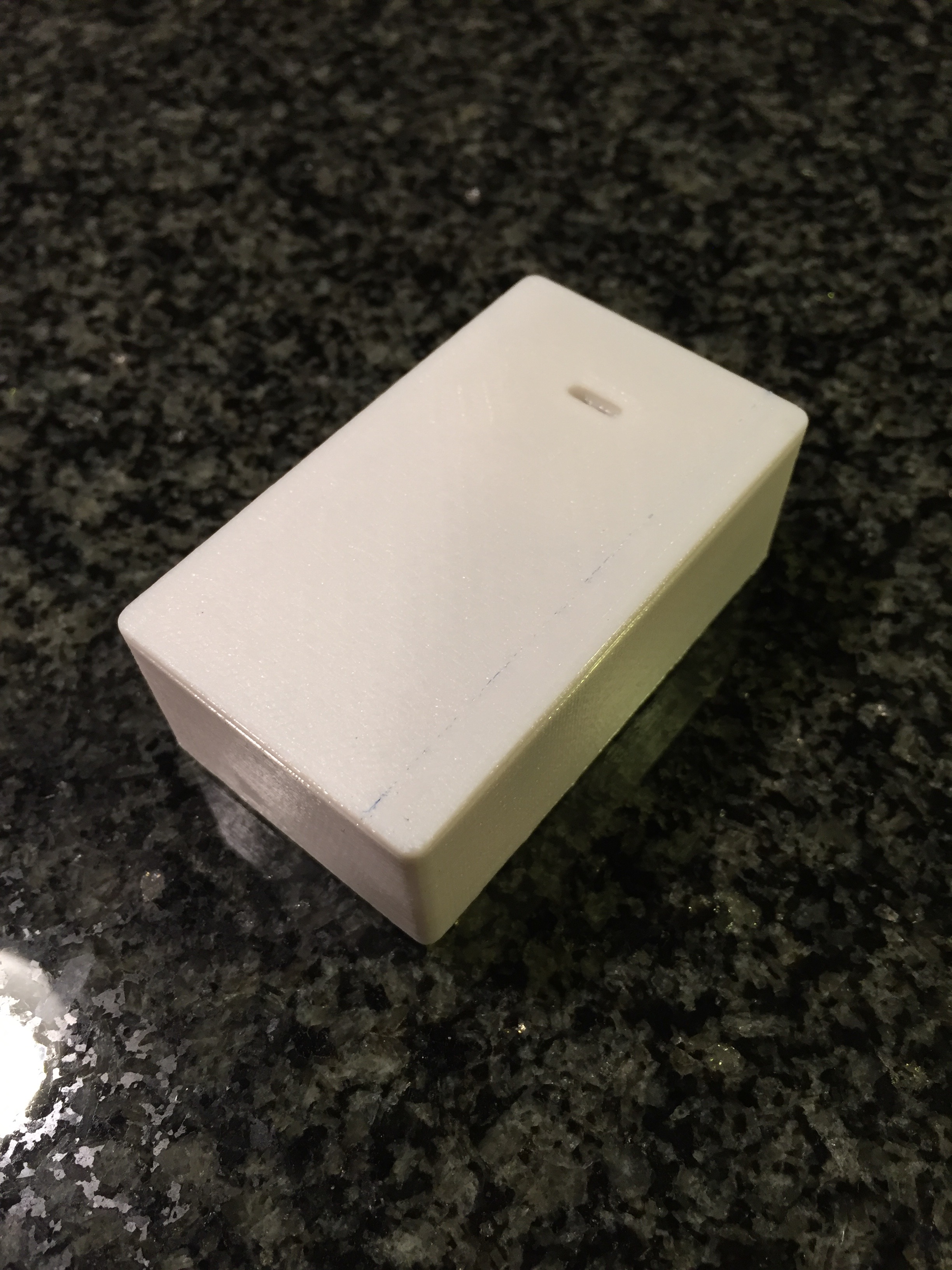
Since I also built a 3D printer lately, I was able to put the sensor into a little box. Now I can easily measure humidity and temperature in my bath room and see it in fhem on a raspberry.Currently I'm working on my next pcb... I will show the next one when I'm finished in a new thread.